1
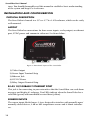
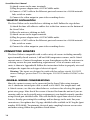
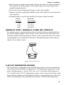
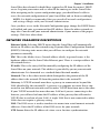
Model FGD-sv4A
User’s Manual
Version 1.3
SensaVideo User’s Manual
Every effort has been made to ensure that the information in
this document is complete, accurate and up-to-date. Sensaphone
assumes no responsibility for the results of errors beyond its control. Sensaphone also cannot guarantee that changes in equipment
made by other manufacturers, and referred to in this manual, will not
affect the applicability of the information in this manual.
Copyright © 2010 by SENSAPHONE®
First Edition, version 1.3, October 2010
Written and produced by SENSAPHONE®.
Please address comments on this publication to:
SENSAPHONE®
901 Tryens Road
Aston, PA 19014
2
Important Safety
Instructions

Your SensaVideo has been carefully designed to give you years of
safe, reliable performance. As with all electrical equipment, however,
there are a few basic precautions you should take to avoid hurting
yourself or damaging the unit:
• Read the installation and operating instructions in this manual
carefully. Be sure to save it for future reference.
• Read and follow all warning and instruction labels on the product
itself.
• To protect the SensaVideo from overheating, make sure all
openings on the unit are not blocked. Do not place on or near a
heat source, such as a radiator or heat register.
• Do not use your SensaVideo near water, or spill liquid of any
kind into it.
• Be certain that your power source matches the rating in the
specifications of this manual. If you’re not sure of the type of
power supply to your facility, consult your dealer or local power
company.
• Do not allow anything to rest on the power cord. Do not locate
this product where the cord will be abused by persons walking on
it.
• Do not overload wall outlets and extension cords, as this can
result in the risk of fire or electric shock.
• Never push objects of any kind into this product through
ventilation holes as they may touch dangerous voltage points or
short out parts that could result in a risk of fire or electric shock.
• To reduce the risk of electric shock, do not disassemble this
product, but return it to Sensaphone Customer Service, or
another approved repair facility, when any service or repair work
is required. Opening or removing covers may expose you to
dangerous voltages or other risks. Incorrect reassembly can cause
electric shock when the unit is subsequently used.
3
SensaVideo User’s Manual
• If anything happens that indicates that your SensaVideo is not
working properly or has been damaged, unplug it immediately and
follow the procedures in the manual for having it serviced. Return
the unit for servicing under the following conditions:
1. The power cord or plug is frayed or damaged.
2. Liquid has been spilled into the product or it has been exposed to water.
3. The unit has been dropped, or the enclosure is damaged.
4. The unit doesn’t function normally when you’re following the operating instructions.
FCC Requirements
Part 15: This equipment has been tested and found to comply with the limits for
a Class A digital device, pursuant to Part 15 of the FCC Rules. These limits are
designed to provide reasonable protection against harmful interference when
the equipment is operated in a commercial environment. This equipment generates, uses and can radiate radio frequency energy and, if not installed and used in
accordance with the instructions, may cause harmful interference to radio communications. Operation of this equipment in a residential area is likely to cause
harmful interference in which case the user will be required to correct the interference at his own expense.
4

1 YEAR LIMITED WARRANTY
PLEASE READ THIS WARRANTY CAREFULLY BEFORE USING THE PRODUCT.
THIS LIMITED WARRANTY CONTAINS SENSAPHONE’S STANDARD TERMS AND
CONDITIONS. WHERE PERMITTED BY THE APPLICABLE LAW, BY KEEPING YOUR
SENSAPHONE PRODUCT BEYOND THIRTY (30) DAYS AFTER THE DATE OF DELIVERY,
YOU FULLY ACCEPT THE TERMS AND CONDITIONS SET FORTH IN THIS LIMITED
WARRANTY.
IN ADDITION, WHERE PERMITTED BY THE APPLICABLE LAW, YOUR INSTALLATION
AND/OR USE OF THE PRODUCT CONSTITUTES FULL ACCEPTANCE OF THE TERMS
AND CONDITIONS OF THIS LIMITED WARRANTY (HEREINAFTER REFERRED TO AS
“LIMITED WARRANTY OR WARRANTY”). IF YOU DO NOT AGREE TO THE TERMS
AND CONDITIONS THIS WARRANTY, INCLUDING ANY LIMITATIONS OF WARRANTY,
INDEMNIFICATION TERMS OR LIMITATION OF LIABILITY, THEN YOU SHOULD NOT
USE THE PRODUCT AND SHOULD RETURN IT TO THE SELLER FOR A REFUND OF THE
PURCHASE PRICE. THE LAW MAY VARY BY JURISDICTION AS TO THE APPLICABILITY
OF YOUR INSTALLATION OR USE ACTUALLY CONSTITUTING ACCEPTANCE OF THE
TERMS AND CONDITIONS HEREIN AND AS TO THE APPLICABILITY OF ANY LIMITATION
OF WARRANTY, INDEMNIFICATION TERMS OR LIMITATIONS OF LIABILITY.
1. WARRANTOR: IN THIS WARRANTY, WARRANTOR SHALL MEAN “DEALER,
DISTRIBUTOR, AND/OR MANUFACTURER.”
2. ELEMENTS OF WARRANTY: THIS PRODUCT IS WARRANTED TO BE FREE FROM
DEFECTS IN MATERIALS AND CRAFTSMANSHIP WITH ONLY THE LIMITATIONS AND
EXCLUSIONS SET OUT BELOW.
3. WARRANTY AND REMEDY: ONE-YEAR WARRANTY — IN THE EVENT THAT THE
PRODUCT DOES NOT CONFORM TO THIS WARRANTY AT ANY TIME DURING THE TIME
OF ONE YEAR FROM ORIGINAL PURCHASE, WARRANTOR WILL REPAIR THE DEFECT
AND RETURN IT TO YOU AT NO CHARGE.
THIS WARRANTY SHALL TERMINATE AND BE OF NO FURTHER EFFECT AT THE TIME
THE PRODUCT IS: (1) DAMAGED BY EXTRANEOUS CAUSE SUCH AS FIRE, WATER,
LIGHTNING, ETC. OR NOT MAINTAINED AS REASONABLE AND NECESSARY; OR (2)
MODIFIED; OR (3) IMPROPERLY INSTALLED; OR (4) MISUSED; OR (5) REPAIRED OR
SERVICED BY SOMEONE OTHER THAN WARRANTORS’ AUTHORIZED PERSONNEL OR
SOMEONE EXPRESSLY AUTHORIZED BY WARRANTOR’S TO MAKE SUCH SERVICE OR
REPAIRS; (6) USED IN A MANNER OR PURPOSE FOR WHICH THE PRODUCT WAS NOT
INTENDED; OR (7) SOLD BY ORIGINAL PURCHASER.
LIMITED WARRANTY, LIMITATION OF DAMAGES AND DISCLAIMER OF LIABILITY FOR
DAMAGES: THE WARRANTOR’S OBLIGATION UNDER THIS WARRANTY IS LIMITED
TO REPAIR OR REPLACEMENT OF THE PRODUCT, AT THE WARRANTOR’S OPTION
AS TO REPAIR OR REPLACEMENT. IN NO EVENT SHALL WARRANTORS BE LIABLE
OR RESPONSIBLE FOR PAYMENT OF ANY INCIDENTAL, CONSEQUENTIAL, SPECIAL
AND/OR PUNITIVE DAMAGES OF ANY KIND, INCLUDING BUT NOT LIMITED TO ANY
LABOR COSTS, PRODUCT COSTS, LOST REVENUE, BUSINESS INTERRUPTION LOSSES,
LOST PROFITS, LOSS OF BUSINESS, LOSS OF DATA OR INFORMATION, OR FINANCIAL
LOSS, FOR CLAIMS OF ANY NATURE, INCLUDING BUT NOT LIMITED TO CLAIMS IN
CONTRACT, BREACH OF WARRANTY OR TORT, AND WHETHER OR NOT CAUSED
BY WARRANTORS’ NEGLIGENCE. IN THE EVENT THAT IT IS DETERMINED IN ANY
ADJUDICATION THAT THE LIMITED WARRANTIES OF REPAIR OR REPLACEMENT ARE
INAPPLICABLE, THEN THE PURCHASER’S SOLE REMEDY SHALL BE PAYMENT TO THE
PURCHASER OF THE ORIGINAL COST OF THE PRODUCT, AND IN NO EVENT SHALL
5
SensaVideo User’s Manual
WARRANTORS BE LIABLE OR RESPONSIBLE FOR PAYMENT OF ANY INCIDENTAL,
CONSEQUENTIAL, SPECIAL AND/OR PUNITIVE DAMAGES OF ANY KIND, INCLUDING
BUT NOT LIMITED TO ANY LOST REVENUE, BUSINESS INTERRUPTION LOSSES, LOST
PROFITS, LOSS OF BUSINESS, LOSS OF DATA OR INFORMATION, OR FINANCIAL
LOSS, FOR CLAIMS OF ANY NATURE, INCLUDING BUT NOT LIMITED TO CLAIMS IN
CONTRACT, BREACH OF WARRANTY OR TORT, AND WHETHER OR NOT CAUSED BY
WARRANTORS’ NEGLIGENCE.
WITHOUT WAIVING ANY PROVISION IN THIS LIMITED WARRANTY, IF A
CIRCUMSTANCE ARISES WHERE WARRANTORS ARE FOUND TO BE LIABLE FOR
ANY LOSS OR DAMAGE ARISING OUT OF MISTAKES, NEGLIGENCE, OMISSIONS,
INTERRUPTIONS, DELAYS, ERRORS OR DEFECTS IN WARRANTORS’ PRODUCTS OR
SERVICES, SUCH LIABILITY SHALL NOT EXCEED THE TOTAL AMOUNT PAID BY THE
CUSTOMER FOR WARRANTORS’ PRODUCT AND SERVICES OR $250.00, WHICHEVER IS
GREATER. YOU HEREBY RELEASE WARRANTORS FROM ANY AND ALL OBLIGATIONS,
LIABILITIES AND CLAIMS IN EXCESS OF THIS LIMITATION.
INDEMNIFICATION AND COVENANT NOT TO SUE: YOU WILL INDEMNIFY, DEFEND AND
HOLD HARMLESS WARRANTORS, THEIR OWNERS, DIRECTORS, OFFICERS, EMPLOYEES,
AGENTS, SUPPLIERS OR AFFILIATED COMPANIES, AGAINST ANY AND ALL CLAIMS,
DEMANDS OR ACTIONS BASED UPON ANY LOSSES, LIABILITIES, DAMAGES OR
COSTS, INCLUDING BUT NOT LIMITED TO DAMAGES THAT ARE DIRECT OR INDIRECT,
INCIDENTAL, SPECIAL OR CONSEQUENTIAL, AND INCLUDING ATTORNEYS FEES AND
LEGAL COSTS, THAT MAY RESULT FROM THE INSTALLATION, OPERATION, USE OF, OR
INABILITY TO USE WARRANTORS’ PRODUCTS AND SERVICES, OR FROM THE FAILURE
OF THE WARRANTORS’ SYSTEM TO REPORT A GIVEN EVENT OR CONDITION, WHETHER
OR NOT CAUSED BY WARRANTORS’ NEGLIGENCE.
YOU AGREE TO RELEASE, WAIVE, DISCHARGE AND COVENANT NOT TO SUE
WARRANTORS, THEIR OWNERS, DIRECTORS, OFFICERS, EMPLOYEES, AGENTS,
SUPPLIERS OR AFFILIATED COMPANIES, FOR ANY AND ALL LIABILITIES POTENTIALLY
ARISING FROM ANY CLAIM, DEMAND OR ACTION BASED UPON ANY LOSSES,
LIABILITIES, DAMAGES OR COSTS, INCLUDING BUT NOT LIMITED TO DAMAGES
THAT ARE DIRECT OR INDIRECT, INCIDENTAL, SPECIAL OR CONSEQUENTIAL, AND
INCLUDING ATTORNEYS FEES AND LEGAL COSTS, THAT MAY RESULT FROM THE
INSTALLATION, OPERATION, USE OF, OR INABILITY TO USE WARRANTORS’ PRODUCTS
AND SERVICES, OR FROM THE FAILURE OF THE WARRANTORS’ SYSTEM TO REPORT
A GIVEN EVENT OR CONDITION, WHETHER OR NOT CAUSED BY WARRANTORS’
NEGLIGENCE, EXCEPT AS NECESSARY TO ENFORCE THE EXPRESS TERMS OF THIS
LIMITED WARRANTY.
EXCLUSIVE WARRANTY: THE LIMITED WARRANTY OR WARRANTIES DESCRIBED
HEREIN CONSTITUTE THE SOLE WARRANTY OR WARRANTIES TO THE PURCHASER.
ALL IMPLIED WARRANTIES ARE EXPRESSLY DISCLAIMED, INCLUDING: THE
WARRANTY OF MERCHANTABILITY AND THE WARRANTY OF FITNESS FOR A
PARTICULAR USE AND THE WARRANTY OF FITNESS FOR A PARTICULAR PURPOSE AND
THE WARRANTY OF NON-INFRINGEMENT AND/OR ANY WARRANTY ARISING FROM A
COURSE OF DEALING, USAGE, OR TRADE PRACTICE.
IT MUST BE CLEAR THAT THE WARRANTORS ARE NOT INSURING YOUR PREMISES
OR BUSINESS OR GUARANTEEING THAT THERE WILL NOT BE DAMAGE TO YOUR
PERSON OR PROPERTY OR BUSINESS IF YOU USE THIS PRODUCT. YOU SHOULD
MAINTAIN INSURANCE COVERAGE SUFFICIENT TO PROVIDE COMPENSATION FOR
ANY LOSS, DAMAGE, OR EXPENSE THAT MAY ARISE IN CONNECTION WITH THE USE
OF PRODUCTS OR SERVICES, EVEN IF CAUSED BY WARRANTORS’ NEGLIGENCE. THE
WARRANTORS ASSUME NO LIABILITY FOR INSTALLATION OF THE PRODUCT AND/
OR INTERRUPTIONS OF THE SERVICE DUE TO STRIKES, RIOTS, FLOODS, FIRE, AND/OR
ANY CAUSE BEYOND SELLER’S CONTROL, FURTHER SUBJECT TO THE LIMITATIONS
6

EXPRESSED IN ANY LICENSE AGREEMENT OR OTHER AGREEMENT PROVIDED BY
WARRANTORS TO PURCHASER.
THE AGREEMENT BETWEEN THE WARRANTORS AND THE PURCHASER, INCLUDING
BUT NOT LIMITED TO THE TERMS AND CONDITIONS HEREIN SHALL NOT BE
GOVERNED BY THE CONVENTION FOR THE INTERNATIONAL SALE OF GOODS. WHERE
APPLICABLE, THE UNIFORM COMMERCIAL CODE AS ADOPTED BY THE STATE OF
DELAWARE SHALL APPLY.
4. PROCEDURE FOR OBTAINING PERFORMANCE OF WARRANTY: IN THE
EVENT THAT THE PRODUCT DOES NOT CONFORM TO THIS WARRANTY, THE PRODUCT
SHOULD BE SHIPPED OR DELIVERED FREIGHT PREPAID TO A WARRANTOR WITH
EVIDENCE OF ORIGINAL PURCHASE.
5. LEGAL REMEDIES AND DISCLAIMER: SOME JURISDICTIONS MAY NOT ALLOW,
OR MAY PLACE LIMITS UPON, THE EXCLUSION AND/OR LIMITATION OF IMPLIED
WARRANTIES, INCIDENTAL DAMAGES AND/OR CONSEQUENTIAL DAMAGES FOR
SOME TYPES OF GOODS OR PRODUCTS SOLD TO CONSUMERS AND/OR THE USE OF
INDEMNIFICATION TERMS. THUS, THE EXCLUSIONS, INDEMNIFICATION TERMS AND
LIMITATIONS SET OUT ABOVE MAY NOT APPLY, OR MAY BE LIMITED IN THEIR
APPLICATION, TO YOU. IF THE IMPLIED WARRANTIES CAN NOT BE EXCLUDED, AND
THE APPLICABLE LAW PERMITS LIMITING THE DURATION OF IMPLIED WARRANTIES,
THEN THE IMPLIED WARRANTIES HEREIN ARE TO BE LIMITED TO THE SAME
DURATION AS THE APPLICABLE WRITTEN WARRANTY OR WARRANTIES HEREIN. THE
WARRANTY OR WARRANTIES HEREIN MAY GIVE YOU SPECIFIC LEGAL RIGHTS THAT
WILL DEPEND UPON THE APPLICABLE LAW. YOU MAY ALSO HAVE OTHER LEGAL
RIGHTS DEPENDING UPON THE LAW IN YOUR JURISDICTION.
6. CHOICE OF FORUM AND CHOICE OF LAW: IN THE EVENT THAT A DISPUTE
ARISES OUT OF OR IN CONNECTION WITH THIS LIMITED WARRANTY, THEN ANY
CLAIMS OR SUITS OF ANY KIND CONCERNING SUCH DISPUTES SHALL ONLY AND
EXCLUSIVELY BE BROUGHT IN EITHER THE COURT OF COMMON PLEAS OF DELAWARE
COUNTY, PENNSYLVANIA OR THE UNITED STATES DISTRICT COURT FOR THE EASTERN
DISTRICT OF PENNSYLVANIA.
REGARDLESS OF THE PLACE OF CONTRACTING OR PERFORMANCE, THIS LIMITED
WARRANTY AND ALL QUESTIONS RELATING TO ITS VALIDITY, INTERPRETATION,
PERFORMANCE AND ENFORCEMENT SHALL BE GOVERNED BY AND CONSTRUED IN
ACCORDANCE WITH THE LAWS OF THE STATE OF DELAWARE, WITHOUT REGARD TO
THE PRINCIPLES OF CONFLICTS OF LAW.
Effective date 05/01/2004
PHONETICS, INC. D.B.A. SENSAPHONE
901 Tryens Road
Aston, PA 19014
Phone: 610.558.2700 Fax: 610.558.0222
www.sensaphone.com
7
SensaVideo User’s Manual
8
Table of Contents
Table of Contents
Chapter 1: Installation . . . . . . . . . . . . . . . . . . . . . . . . . . . . 11
Introduction1 . . . . . . . . . . . . . . . . . . . . . . . . . . . . . . . . . . . . . . . . 1
Features. . . . . . . . . . . . . . . . . . . . . . . . . . . . . . . . . . . . . . . . . . . . . . . . . . . . . . . . . 11
Technical Support . . . . . . . . . . . . . . . . . . . . . . . . . . . . . . . . . . . . . . . . . . . . . . . . 11
About This Manual. . . . . . . . . . . . . . . . . . . . . . . . . . . . . . . . . . . . . 11
INSTALLATION and CONFIGURATION. . . . . . . . . . . . . . . . . . . . . . . . . 12
Physical Description . . . . . . . . . . . . . . . . . . . . . . . . . . . . . . . . . . . . . . . . . . . . . . 12
Layout . . . . . . . . . . . . . . . . . . . . . . . . . . . . . . . . . . . . . . . . . . . . . . . . . . . . . . . . . . 12
RJ-45 10/100BASE-T Ethernet Port. . . . . . . . . . . . . . . . . . . . . . . . . . . . . . . . . . . . 12
Sensor Inputs. . . . . . . . . . . . . . . . . . . . . . . . . . . . . . . . . . . . . . . . . . . . . . . . . . . . 12
Relay Output . . . . . . . . . . . . . . . . . . . . . . . . . . . . . . . . . . . . . . . . . . . . . . . . . . . . . 13
Power On LED (Green). . . . . . . . . . . . . . . . . . . . . . . . . . . . . . . . . . . . . . . . . . . . . 13
Alarm LED (red) . . . . . . . . . . . . . . . . . . . . . . . . . . . . . . . . . . . . . . . . . . . . . . . . . . . 13
Installation
. . . . . . . . . . . . . . . . . . . . . . . . . . . . . . . . . . . . . . . . 13
Parts Required. . . . . . . . . . . . . . . . . . . . . . . . . . . . . . . . . . . . . . . . . . . . . . . . . . . . 13
Operating Environment. . . . . . . . . . . . . . . . . . . . . . . . . . . . . . . . . . . . . . . . . . . 13
Wall Mount Installation . . . . . . . . . . . . . . . . . . . . . . . . . . . . . . . . . . . . . . . . . . 13
Tabletop Installation. . . . . . . . . . . . . . . . . . . . . . . . . . . . . . . . . . . . . . . . . . . . . . 14
Connecting Sensors. . . . . . . . . . . . . . . . . . . . . . . . . . . . . . . . . . . . 14
General Wiring Considerations. . . . . . . . . . . . . . . . . . . . . . . . . . . . . . . . . . . . 14
Normally open / normally closed dry contacts . . . . . . . . . . . . . . . . . . . . 15
2.8K/10k Temperature sensors. . . . . . . . . . . . . . . . . . . . . . . . . . . . . . . . . . . . . . 15
4–20mA Current Loop Transducers . . . . . . . . . . . . . . . . . . . . . . . . . . . . . . . . . 16
Relay Output Wiring. . . . . . . . . . . . . . . . . . . . . . . . . . . . . . . . . . . . 16
Network Configuration. . . . . . . . . . . . . . . . . . . . . . . . . . . . . . . . 17
Network Parameter Descriptions. . . . . . . . . . . . . . . . . . . . . . . . . 19
Installing the Sensaphone Locator Software . . . . . . . . . . . . . . . . . . . . . . . 20
Using the Sensaphone Locator Software . . . . . . . . . . . . . . . . . . . . . . . . . . . 21
Resetting the SensaVideo to Factory Default Settings . . . . . . . . . . . . . . . . 22
Chapter 2: System Configuration. . . . . . . . . . . . . . . . . . . . 23
Introduction23
System Configuration Menu. . . . . . . . . . . . . . . . . . . . . . . . . . . . . . . . . . . . . . . 24
E-mail Setup . . . . . . . . . . . . . . . . . . . . . . . . . . . . . . . . . . . . . . . . . . . . . . . . . . . . . . 24
Advanced Settings . . . . . . . . . . . . . . . . . . . . . . . . . . . . . . . . . . . . . . . . . . . . . . . 25
9
SensaVideo User’s Manual
Chapter 3: Sensor Programming. . . . . . . . . . . . . . . . . . . . 27
Chapter 4: User Programming . . . . . . . . . . . . . . . . . . . . . . 29
Chapter 5: Video Output. . . . . . . . . . . . . . . . . . . . . . . . . . . . 31
Chapter 6: Alarm Notification . . . . . . . . . . . . . . . . . . . . . . 33
Alarm Processing . . . . . . . . . . . . . . . . . . . . . . . . . . . . . . . . . . . . . . . . . . . . . . . . 33
Chapter 7: History. . . . . . . . . . . . . . . . . . . . . . . . . . . . . . . . . 35
Chapter 8: Input Values and Datalog History via XML . . 37
Retrieving Realtime Input Values via XML . . . . . . . . . . . . . . . . . . . . . . . . . . . . . 37
Retrieving Datalogged Values via XML. . . . . . . . . . . . . . . . . . . . . . . . . . . . . . . 37
Appendix A: Weekly Testing Procedure. . . . . . . . . . . . . . . . 41
Appendix B: Accessories. . . . . . . . . . . . . . . . . . . . . . . . . . . . 43
Appendix C: Specifications. . . . . . . . . . . . . . . . . . . . . . . . . . 45
Alert Zones. . . . . . . . . . . . . . . . . . . . . . . . . . . . . . . . . . . . . . . . . . . . . . . . . . . . . . 45
LED Indicators. . . . . . . . . . . . . . . . . . . . . . . . . . . . . . . . . . . . . . . . . . . . . . . . . . . . 45
Communication types. . . . . . . . . . . . . . . . . . . . . . . . . . . . . . . . . . . . . . . . . . . . . 45
Power Supply. . . . . . . . . . . . . . . . . . . . . . . . . . . . . . . . . . . . . . . . . . . . . . . . . . . . . 45
Environmental. . . . . . . . . . . . . . . . . . . . . . . . . . . . . . . . . . . . . . . . . . . . . . . . . . . 45
Physical . . . . . . . . . . . . . . . . . . . . . . . . . . . . . . . . . . . . . . . . . . . . . . . . . . . . . . . . . 45
Network . . . . . . . . . . . . . . . . . . . . . . . . . . . . . . . . . . . . . . . . . . . . . . . . . . . . . . . . 45
Video Output. . . . . . . . . . . . . . . . . . . . . . . . . . . . . . . . . . . . . . . . . . . . . . . . . . . . . 45
Relay Output . . . . . . . . . . . . . . . . . . . . . . . . . . . . . . . . . . . . . . . . . . . . . . . . . . . . . 46
Appendix D: Thermistors . . . . . . . . . . . . . . . . . . . . . . . . . . . 47
2.8K Thermistor Data. . . . . . . . . . . . . . . . . . . . . . . . . . . . . . . . . . . . . . . . . . . . . . . .
10K Thermistor Data. . . . . . . . . . . . . . . . . . . . . . . . . . . . . . . . . . . . . . . . . . . . . . . 47
Appendix E: Returning the Unit for Repair . . . . . . . . . . . . 49
Appendix F: Test Log . . . . . . . . . . . . . . . . . . . . . . . . . . . . . . . 51
10
Chapter 1: Installation
Chapter 1: Installation
Introduction
Congratulations on your purchase of the SensaVideo. The system is designed to
provide an easy way to bring real time sensor values into your video surveillance
system. The internet browser–based programming makes the device easy to use from
any computer on your network. Monitored conditions can include temperature,
humidity levels, line voltage, leak detection, UPS systems, and more. The system allows
multiple users to be notified immediately of any detected problems. Notification can
occur via e–mail or SMS (text message).
Features
The SensaVideo includes the following key features:
n Four sensor inputs to monitor environmental conditions and/or alarm
contacts from other computer equipment such as UPS systems.
n Relay output that trips on alarm
n Emulates an analog security camera (NTSC or PAL)
n 10/100BASE-T Ethernet port.
n Motion JPEG video stream
n Compact design allows wall-mount or tabletop installation.
n Embedded web page to program and manage your SensaVideo system.
n Notification via e–mail or SMS (text message).
Technical Support
If any questions arise upon installation or operation of the SensaVideo, please
contact our Technical Service Department at 610.558.2700 and have the following
information available:
• Date of purchase __________________
• Serial number __________________
Technical support is available from 8:00 AM to 5:00 PM, M-F, eastern time.
About This Manual
This manual comprises the instructions and commands necessary to install and
program the SensaVideo. Additional summary and application chapters are
included to help you speed programming and to understand the SensaVideo’s fea-
11
SensaVideo User’s Manual
tures. You should thoroughly read this manual to establish a basic understanding
of the system and keep it as a reference.
INSTALLATION and CONFIGURATION
Physical Description
The SensaVideo is housed in a 5.5”w x 3.7”h x 1.4”d enclosure, which can be easily
wall mounted.
Layout
The SensaVideo has connections for four sensor inputs, a relay output, an ethernet
port, 5VDC power and composite video out. See figure below:
Figure 1: Front Panel Layout of the SensaVideo
1) Video Output
2) Sensor Input Terminal Strip
3) Ethernet Jack
4) 12V DC Power
5) Relay Output Terminal Strip
RJ-45 10/100BASE-T Ethernet Port
This jack is for connecting to your network so that the SensaVideo can send alarm
messages and display it’s webpage. Two LEDs indicate when the SensaVideo has a
valid link (green) and transmitted/received data (yellow).
Sensor Inputs
The sensor inputs labeled zones 1-4 are designed to interface with normally open/
normally closed devices, 2.8K or 10K temperature sensors and 4-20mA transducers.
12
Chapter 1: Installation
Relay Output
The SensaVideo includes a SPST relay output that can be used to turn on a light,
siren, or other device whenever an alarm occurs.
Power On LED (Green)
This light indicates that the SensaVideo unit is powered and operational.
Alarm LED (red)
The Alarm LED is a visual indication that an alarm exists.
Installation
This section provides information on:
• Operating environment
• Installation
• Connecting sensors
• Network Configuration
Parts Required
• Phillips Screwdriver
• Cat 5 Patch Cable
• Network Hub, Switch, or Router that supports 10 or 100 BASE-T
• Computer w/Network Connection
Operating Environment
Before you install the SensaVideo be sure that your operating environment meets
the physical requirements of the equipment.
Operating Temperature:
32º–122º Fahrenheit (0º–50º C)
Humidity: 5–90 %RH, non-condensing
Power: 115VAC 60 Hz outlet within 6’
Wall Mount Installation
The SensaVideo can be wall mounted using the included dry wall anchors and
screws. Follow the steps below:
1) Install four drywall anchors (if necessary) according to the diagram below.
Attach the SensaVideo using the four #6 tapping screws.
6.75
3.5
13
SensaVideo User’s Manual
2) Attach sensors to the zone terminals.
3) Plug the power adaptor into a 115VAC 60Hz outlet.
4) Connect a CAT5 cable to the Ethernet port and connect to a 10/100 network
hub, switch or router.
5) Connect the video output to your video recording device.
Tabletop Installation
The SensaVideo can be installed on a tabletop or shelf. Follow the steps below:
1) Attach the four self-adhesive rubber feet to the four corners on the bottom of
the SensaVideo.
2) Place the unit on a tabletop or shelf.
3) Attach sensors to the input terminals.
4) Plug the power adaptor into a 115VAC 60Hz outlet.
5) Connect a CAT5 cable to the Ethernet port and connect to a 10/100 network
hub, switch or router.
6) Connect the video output to your video recording device.
Connecting Sensors
The SensaVideo is compatible with a wide variety of sensors including normally
open/normally closed contacts, 2.8K and 10K temperature sensors, and 4–20mA
current sources. Contact Sensaphone or your Sensaphone reseller for assistance in
selecting sensors for your monitoring requirements. A list of sensors and accessories is shown in Appendix B. Follow the instructions below to properly wire and
configure the inputs for each type of electrical signal.
Warning: The inputs are designed to work with low voltage signals. DO NOT
connect voltages greater than 5V to the inputs. DO NOT connect 120VAC to the
inputs.
General Wiring Considerations
Most dry contact sensors can be connected to the SensaVideo using inexpensive 2-conductor twisted-pair cable as small as #24 AWG. For temperature and
4–20mA sensors, use the wire chart below as a reference for selecting the appropriate wire gauge. Note that if the sensor is located far from the unit or if you are
running cable in an electrically noisy environment, you should seriously consider
using twisted pair shielded cable. This will shield the signal from electrical interference, thereby preventing false readings and/or damage to the unit. For your
convenience, Sensaphone has 22 gauge shielded cable available in 50’ lengths (part
number FGD-0010). To minimize electrical noise coupling between sensor wires
and other wiring, follow the guidelines listed below:
14
Chapter 1: Installation
• Route the power supply and network cables to the unit by a separate path then
the wiring to the sensor inputs. Where paths must cross, their intersection
should be perpendicular.
• Do not run sensor wiring and AC power in the same conduit.
• Segregate wiring by signal type. Bundle wiring with similar electrical characteristics together.
• If shielded cable is used tie the shield to the negative input terminal.
WiringMinimum
Distance
Wire Gauge
700’
#24 AWG
1500’
#22 AWG
2500’
#20 AWG
Normally open / normally closed dry contacts
Dry contact sources consist of alarm relays or switches that are isolated and have
no external voltage applied. These devices can be connected directly to the zone
terminals without regard for polarity. Choose a zone and connect the wires to the
corresponding screw terminals for that zone. The following figure shows how to
connect a dry contact sensor:
Wiring a Dry Contact Sensor
2.8K/10k Temperature sensors
The SensaVideo is compatible with 2.8K/10K temperature sensors that match the
curve data listed in the tables in Appendix D. The monitoring temperature range
of the 2.8K thermistor is -109 to 115ºF (-85º to 57ºC) and the 10K thermistor is
-87° to 168°F (-66° to 76°C). Temperature sensors can be connected directly to the
zone terminals without regard for polarity. Choose an input and connect the wires
to the corresponding screw terminals for that zone. 2.8K and 10K temperature
15
SensaVideo User’s Manual
sensors are available from Sensaphone. See Appendix B for part numbers. The figure below shows how to connect a temperature sensor:
Wiring a Temperature Sensor
4–20mA Current Loop Transducers
The inputs on the SensaVideo are compatible with transducers that produce an
analog output current of 4 to 20mA. Such transducers are available to measure
tank and well levels, extreme temperatures, air pressure, water pressure, flow, voltage, current, rotational speed, etc. Contact our technical support department for
assistance regarding your monitoring requirements. Follow the wiring diagrams
below for connecting a 4–20mA device:
External
24V
Power
Supply
FGD-0053
4-20 mA
Transducer
Figure 10: Wiring a 4–20mA device using an external 24 VDC supply.
Relay Output Wiring
The SensaVIDEO includes an SPST relay output that can be used to turn on a
light, siren, or other device whenever an alarm occurs. The output is a normally
open dry contact that can be used for low voltage switching. The relay is rated for
up to 30VAC/VDC 1 Amp. A sample wiring diagram is shown below:
16
Chapter 1: Installation
FGD-SV4A
By SENSAPHONE
Sensor
+1–
Sensor
+2–
Sensor
+3–
Sensor
+4–
Relay
Output
Ethernet
Power
The relay will engage whenever an input is above or below the programmed alarm
limits and the programmed recognition time has been met. It will release as soon
as the input returns to a normal condition.
Network Configuration
The SensaVideo is designed for installation on an Ethernet network. This
involves assigning it an IP address. By default the SensaVideo will try to acquire
an IP address automatically using DHCP. If it is successful you can then use the
Sensaphone Locator program to find the SensaVideo on your network and then
assign it a fixed IP address. The network configuration can be found on the System
Configuration page. If no DHCP server is found the unit will fallback to a fixed IP
address of 192.168.1.250. Follow the instructions below depending on which scenario applies to your network:
Automatic Network Configuration Using DHCP:
If your network supports DHCP then simply plug the network jack into the
SensaVideo’s Ethernet port and turn it on. Allow the unit to finish booting up
(1-2 minutes). Next, install the Sensaphone Locator program on the included
CD ROM. After installation, run the Sensaphone Locator program and click the
Search button. A list of detected SensaVideo’s will be displayed showing their IP
address and MAC address (SensaVideo serial number). Click on the SensaVideo
in the list and then click Connect and your browser will open to the SensaVideo
homepage. Click System Configuration to view the Network Configuration page.
17
SensaVideo User’s Manual
System Configuration page
Network Configuration using a Static IP Address:
If your network does not support DHCP then your SensaVideo will set its IP
address to 192.168.1.250. This address should only be temporarily set. Leaving
this address as the factory default could result in networking conflicts if another
SensaVideo is added to your network.
If your network does not support DHCP then you will have to use one of the following methods to change the IP of the SensaVideo for the first time.
1) Using a standard RJ45 crossover cable (not included) connect your PC’s network jack to the SensaVideo temporarily. Change the IP of your computer’s network connection to something in 192.168.1.xxx that is not the same as the default
IP of the SensaVideo.
After navigating to the system configuration page, you should now be able to
access the network configurations of your SensaVideo, and set them accordingly.
NOTE: It is highly recommended that you consult all network configurations
and settings changes with your Network Administrator.
2) Using a network hub connect only your PC and the SensaVideo to the hub.
Change the IP of your network connection to something in 192.168.1.xxx that is
not the same as the default IP of the SensaVideo. After navigating to the system
configuration page, you should now be able to access the network configurations
of your SensaVideo and set them accordingly.
NOTE: It is highly recommended that you consult all network configurations
and settings changes with your Network Administrator.
18
3) Using a network router that is configured for DHCP server connect both
your SensaVideo and your computer to the router. Power cycle your SensaVideo.
Configure your computer’s network connection for using DHCP. Once the
Chapter 1: Installation
SensaVideo has rebooted it should have acquired an IP from the router’s DHCP
server. Log into your router and see what IP the router gave to the SensaVideo.
After navigating to the system configuration page, you should now be able to
access the network configurations of your SensaVideo and set them accordingly.
NOTE: It is highly recommended that you consult all network configurations
and settings changes with your Network Administrator.
Once you have access to the Network Configuration page change the DHCP Status
to Disabled and enter a permanent fixed IP address. Enter the other network settings also. Consult with your network administrator if your unsure of the proper
settings. Click Save when done.
Network Parameter Descriptions
Ethernet Mode: Selecting DHCP means that the SensaVideo will automatically
obtain an IP address on the network using Dynamic Host Configuration Protocol
(DHCP). Selecting static means that you will have to configure the network
parameters manually.
HW: This is the Media Access Control address which, in general terms, is the
hardware address for the SensaVideo Ethernet port. There is a unique address for
all network devices.
IP/Addr: This is the entry field for manually configuring the IP address of the
SensaVideo on your network. This address is provided by you or your network
administrator. It is formatted as a standard dotted decimal number.
Netmask: This is the subnet mask which distinguishes the portion of the IP
address that is the network ID from the portion that is the station ID.
Gateway: A TCP/IP network must have a gateway to communicate beyond the
LAN identified by the network ID. A gateway is a computer or router that is connected to two different networks and can move TCP/IP data from one to the other.
If your TCP/IP network has more than one LAN or if you are connecting to the
Internet, you will need to know the IP address of the gateway that will transfer
TCP/IP data in and out of your LAN. A single LAN that is not connected to other
LANs does not require a gateway setting.
DNS: The DNS server is used to translate site names into actual numeric network
addresses. Enter the IP address of the DNS server for your network.
NTP Server: Enter the IP address of a time server for time synchronization.
19
SensaVideo User’s Manual
Installing the Sensaphone Locator Software
The Sensaphone Locator software is used to find your SensaVideo on your network. This is convenient when your SensaVideo was configured using DHCP since
it will tell you the IP address that was assigned to your SensaVideo and provide a
Connect button to open a web browser window to the device’s web page.
Installation Instructions
1. Insert the SensaVideo CD into your computer.
2. Double click install_locator.exe
You will now see the Installation Options screen:
You will want to leave the Locator executable checked. To prevent the creation of a
Start Menu or Desktop shortcut, simply uncheck the box next to the option.
When you are satisfied with the installation options, press the Next button.
You are now presented with the following dialog:
This dialog allows you to specify the location where the executable will be
installed. When you are satisfied with this value, press the Install button.
20
Chapter 1: Installation
The installation will be performed and a progress bar will be displayed to inform
you of the application’s progress. When the installation has been completed, you
will see the following:
Press the OK button to continue. Then click Close. The Sensaphone Locator application is now installed.
Using the Sensaphone Locator Software
Run the Sensaphone Locator application by double-clicking the Sensaphone
Locator icon on your desktop, or selecting Start -> Programs -> Sensaphone
Locator -> Sensaphone Locator. The Sensaphone Locator application will display a
screen similar to the one below:
Pressing the Search button will rescan your network for any Sensaphone devices
that may be connected. Your specific device can be identified by using the MAC
Address field of the Sensaphone Locator, which will be identical to your serial
number. Click on your device within the Sensaphone Locator application and click
the Connect button. Your web browser will launch, taking you to the SensaVideo’s
homepage. Your device is now ready for use. Be sure to read the Network
Configuration section of the manual for further configuration options - such as
configuring a static IP address.
21
SensaVideo User’s Manual
Resetting the SensaVideo to Factory Default Settings
In the event that you can no longer connect to your SensaVideo or simply have
forgotten the password, you can reset the unit to factory defaults. On the bottom
of the enclosure is a small hole. Beneath the hole is a push button. Insert a paper
clip or similar item into the hole and push the button for 5 seconds while the
device is powered on. The SensaVideo will erase all of its programming and then
reboot automatically.
22
Chapter 2: System Configuration
Chapter 2: System Configuration
Introduction
The SensaVideo is completely programmable from the internal webpage. This
makes it easy to setup, program, and utilize the features of the device. The webpage can be accessed by opening your internet browser (Internet Explorer, Firefox,
Safari, …) and entering the IP address of your SensaVideo (see the Network
Configuration section in Chapter 1 for assistance). The menu items along the red
bar at the top of screen will help you locate specific programming parameters and
features. The Summary screen is your main page to view the current status of all
monitored conditions.
Summary Screen
23
SensaVideo User’s Manual
System Configuration Menu
The System Configuration section is where you configure your network , e-mail,
and Time server settings. The network configuration is covered in Chapter 1.
Enter a Unit Name and Location in the entry boxes at the bottom of the screen.
These will help identify where the alarms are originating from when received
via e–mail or text message. The last entry on the left column is for an NTP Time
Server. This should be configured with the IP address of an available time server.
There are several free ones available on the internet hosted by the NIST (such
as 129.6.15.28 in Maryland), but you may also have one available on your local
network. You must also configure your Time Zone in order for the time to be displayed correctly when an alarm occurs.
You can also secure the programming in your SensaVIDEO by enabling the WEB
Security option. When enabled, you must enter a Username and Password to gain
access to the device’s web page. Click the Logout button after a programming session to secure the device.
Click Save after making any programming changes.
E-mail Setup
To have the unit send e-mail or SMS Text messages, you need to set the SMTP
Server name, port number, and the Return e-mail Address. If your SMTP server
requires authentication then check the Security Enabled box and fill-in the
Username and Password (if required). The SensaVIDEO also allows you to change
the SMTP port number in the event that your internet service provider is using a
non-standard port. Port 25 is the standard port number, but 587 is also becoming
more common as well.
Note: The SensaVideo will not work with SMTP servers that require TLS or SSL
encryption. As a result, it will not work with web-based e-mail providers such
24
Chapter 2: System Configuration
Gmail, Hotmail, Yahoo!Mail, or AOL. If you do not have a compatible SMTP
server available to you, then contact our Technical support for other options.
Advanced Settings
The Advanced screen provides numerous options to configure the operation of the
SensaVIDEO. These include the color scheme of the video output, the font size,
video format (NTSC/PAL), Motion JPEG streaming, and firmware updates. The
colors are specified using hexadecimal codes and can be configured to your specific needs. The Video Mode can be configured for either NTSC or PAL. This should
be set to match the format of your analog video recording device. The Motion
JPEG streaming feature can be used to capture the graphical video image into a
browser or network video recording device. The Port number can be configured
as needed (default 8080). Firmware updates will be available on the SensaVIDEO
website to add features, improve performance or fix problems. Have your firmware version available when contacting technical support. A sample screen of the
Advanced menu is shown below:
25
SensaVideo User’s Manual
26
Chapter 3: Sensor Programming
Chapter 3: Sensor Programming
This chapter explains how to program the Zone Inputs for monitoring and alarming based on your requirements. The SensaVideo features numerous settings for
customizing the operation of the device. To begin, click on the zone name from
the Summary Screen. The following screen will appear:
Zones page
The Zone Programming screen allows you to configure the sensor type and alarm
parameters, as well as the graphic image and scale that appears on the Video output. The parameter descriptions below will help you to configure the sensor for
your application. Note that some parameters, such as Table High and Low, will
only appear if a 4-20mA sensor type is selected.
Input Enabled: Checking this box will activate the input and its value will display
on the web page Summary screen as well as the Video Output.
Enable/Disable: This setting determines if the Zone is being used (Enabled) or not
(Disabled). Selecting Disabled will remove the gauge from the Summary screen.
Alarm Enabled: Checking this box will activate the alarm monitoring and notification features. If the input exceeds the limits and meets the programmed recognition time, then an alarm message will be sent to all Users.
Type: Choose the type of sensor you are connecting to the Zone input. For temperature sensors choose either degrees F or C.
Recognition Time: This is the length of time that an alarm condition must be
present before a valid alarm exists and message delivery is started.
Units: Enter a description which corresponds to the property you’re monitoring
(e.g. °F, %RH, PSI, GPM, RPM,…)
27
SensaVideo User’s Manual
Graphic: This selects the type of graphic element that will appear on the
Video output for the selected zone. The options are: None, Dial Gauge, Tank,
Thermometer, and Show Gauge.
Graphic Low: This value sets the bottom of scale for the selected graphic type.
Graphic High: This value sets the top of scale for the selected graphic type.
Table Low: The Table Low value is used to define the lower range (4mA) of your
4-20mA sensor.
Table High: The Table High value is used to define the upper range (20mA) of
your 4-20mA sensor.
Calibration: This field can be used to offset the Zone value either positive or
negative if there is some error in the reading.
Alarm Low: This is used to determine the low level at which a temperature or
4–20mA Zone has reached the alarm threshold. The value must fall below the
Alarm Limit to trip an alarm.
Alarm High: This is used to determine the high level at which a temperature or
4–20mA Zone has reached the alarm threshold. The value must exceed the Alarm
Limit to trip an alarm.
28
Chapter 4: User Programming
Chapter 4: User Programming
This chapter explains how to setup User accounts for receiving Alarm Messages.
To begin, click on Users from the menu bar. The following screen will appear:
User Programming Screen
The SensaVideo allows you to have up to 8 User notification entries. Each entry
can be either e-mail or sms-text message. In the User Description field enter the
Users name, then select the Message Type (either E-mail or SMS). For e-mail, just
enter the e-mail address in the last field. For SMS, select your cellular carrier then
enter your 10 digit telephone number (area code + number). Click Save when finished.
You can test the notification programming by clicking the Test E-mail button. This
will send a test message to all listed e-mail/sms entries.
29
SensaVideo User’s Manual
30
Chapter 5: Video Output
Chapter 5: Video Output
The SensaVIDEO graphical image can be monitored or recorded using either an
analog capture DVR (Digital Video Recorder) or a digital capture NVR (Network
Video Recorder). The BNC connector on the front of the unit provides an analog
video signal in either NTSC of PAL formats. The video format is configurable on
the Advanced programming page of the System Configuration screen. You can
also capture the image using the streaming Motion JPEG over your network. You
must first enable this option on the Advanced programming screen as mentioned
above. The default port for streaming the motion JPEG is 8080, but you may
change this as desired. Click Save after making any changes.
The video image will contain the value of one or more inputs along with a bar or
angular level gauge which can be scaled to fit your application. In the event that
an input exceeds the alarm limits the status will change from “Normal” to “Alarm”
and it will blink. Only inputs which are enabled will appear in the display. If you
would prefer to only have one input shown, connect your sensor to Input #1 and
disable all of the other Inputs. This will enlarge the image to the full screen size for
Input #1 only. A sample screen of four sensors is shown below:
The type of gauge can be chosen on the Zone Programming screen. A different
gauge can be assigned for each input. There are four types: Thermometer, Dial
Gauge, Tank, and Show Gauge. An example of each is shown below:
Fig 1. Thermometer
31
SensaVideo User’s Manual
Fig 2. Dial Gauge
Fig 3. Tank
Fig 4. Show Gauge
Each gauge can be scaled to optimize the display for your application. On the
Zone Programming screen set the Graphic High and Graphic Low values to customize the range.
32
Chapter 6: Alarm Notification
Chapter 6: Alarm Notification
Once you have finished installing and programming the SensaVideo the unit is
fully operational. Be sure to test each sensor to make sure your alarm messages
will be delivered as expected. Below is a description of how the internal logic handles alarm message delivery for enabled inputs.
Alarm Processing
When a zone exceeds the programmed alarm limit (or if a contact changes
state) the SensaVideo will start its alarm recognition timer and the Status on
the Summary screen will change from OK to Waiting, to indicate that the zone
may become an alarm if the fault condition exceeds the programmed recognition time. If the fault becomes an alarm, the SensaVideo will display the Status as
either High, Low or Alarm, in red, to indicate that an alarm exists and the Last
Alarm time-stamp will update to reflect the time of the alarm. Note that if Alarm
Delivery is disabled while an alarm condition exists, no messages will be delivered.
Once an alarm meets the recognition time, the SensaVideo will send the alarm
message.
33
SensaVideo User’s Manual
34
Chapter 7: History
Chapter 7: History
The SensaVIDEO includes a history log that will keep track of system events and
input values. The logged event messages include programming changes, input
alarms, messages sent, etc… Input or Data logging must be enabled and an interval must be set. The default interval is 5 minutes. The History log can be queried
by selecting a start and end date and choosing to view either Event messages, Data
values, or All. A sample programming screen is shown below:
Select the type of data you wish to query and the time frame, then click View Data.
See sample data log query below:
35
SensaVideo User’s Manual
36
Chapter 8: Input Values and Datalog History via XML
Chapter 8: Input Values and
Datalog History via XML
The Sensavideo supports XML (Extensible Markup Language) for the purpose of
retrieving realtime input values, as well as stored datalog history, of the four input
channels. The URL format for retrieving this information and the resulting XML
data is shown below.
Retrieving Realtime Input Values via XML
Real-time data URL: “IP_ADDRESS/cgi-bin/video4-cgi?Q1=9”
(where IP_ADDRESS is the numeric IP address of the device)
Query parameters passed on URL line:
Q1=9
The URL above returns the current values of the 4 inputs, XML formatted as:
<DATA>
<REC>
<TIME>01/01/2010 12:00:00</TIME>
<INPUT ID=”1”>1.0</INPUT>
<INPUT ID=”2”>1.0</INPUT>
<INPUT ID=”3”>1.0</INPUT>
<INPUT ID=”4”>1.0</INPUT>
</REC>
</DATA>
In the example above the current time is 01/01/2010 12:00:00 in 24 hour format.
All data values are 1.0
Retrieving Datalogged Values via XML
Datalog data URL:
“IP_ADDRESS/cgi-bin/video4-cgi?Q1=10&Q2=10/19/2010
12%3A00%3A00&Q3=10/19/2010 14%3A00%3A00&Q4=1”
37
SensaVideo User’s Manual
(where IP_ADDRESS is the numeric IP address of the device)
Query parameters passed on URL line:
Q1=10
Q2=starting date/time in 24 hour format.
The “:” time separators must be URL encoded as %3A.
The date and time must be separated by one space character.
Q3=ending date/time in 24 hour format
The “:” time separators must be URL encoded as %3A.
The date and time must be separated by one space character.
Q4=sort order, 0=ascending 1=descending
The example above gets the data between 10/19/2010 12:00:00 and 10/19/2010
14:00:00 in descending order.
Listed below is an example of the returned XML formatted Datalog values:
<DATA>
38
<REC>
<TIME>10/19/2010 14:00:00”</TIME>
</REC>
<INPUT ID=”1”>1.0</INPUT>
<INPUT ID=”2”>1.0</INPUT>
<INPUT ID=”3”>1.0</INPUT>
<INPUT ID=”4”>1.0</INPUT>
<REC>
<TIME>10/19/2010 13:59:00”</TIME>
<INPUT ID=”1”>1.0</INPUT>
<INPUT ID=”2”>1.0</INPUT>
<INPUT ID=”3”>1.0</INPUT>
<INPUT ID=”4”>1.0</INPUT>
Chapter 8: Input Values and Datalog History via XML
</REC>
|
|
<REC>
<TIME>10/19/2010 12:00:00”</TIME>
<INPUT ID=”1”>1.0</INPUT>
<INPUT ID=”2”>1.0</INPUT>
<INPUT ID=”3”>1.0</INPUT>
<INPUT ID=”4”>1.0</INPUT>
</REC>
</DATA>
Any errors will return a message enclosed in <ERROR> </ERROR> tags
39
SensaVideo User’s Manual
40
Appendix A: Weekly Testing Procedure
Appendix A: Weekly Testing Procedure
We recommend that you test your Sensaphone weekly to be sure it is functioning
properly. This will ensure that when a problem arises the Sensaphone will be ready
to alert the appropriate personnel.
There are several tests that can be performed:
1.) Create an alarm on each zone by tripping all connected sensors.
Temperature sensors: Heat or cool the sensor.
Motion sensors: Have someone walk in front of the sensor.
Door/window sensors: open the door/window.
Water sensors: Apply a small amount of water beneath the sensor or use a wet
towel and touch it to the sensor probes.
Humidity sensors: Raise the humidity around the sensor by holding a cup of very
hot water beneath the sensor.
2.) Allow the unit to contact all programmed users. This will make sure that the
Sensaphone is programmed properly. It will also prepare personnel to respond
appropriately when they receive a message from the Sensaphone.
3.) Test the battery (if installed) by unplugging the AC adapter and making sure
that the Sensaphone continues to function. Keep the AC adapter unplugged so that
a Power Failure alarm occurs. Plug in the AC adapter after the unit has finished.
4.) Keep a log of your tests, noting the date and whether the SensaVideo passed in
each category tested. An example of such a log is shown below. (See “Test Log” at
the end of this manual.)
SensaVideo Test Log
Date
Inputs
Alarm
Battery
07/19/10
08/20/10
09/19/10
If you require assistance, call Sensaphone Technical Support at 610-558-2700.
41
SensaVideo User’s Manual
42
Appendix B: Accessories
Appendix B: Accessories
The sensors listed below are available from Sensaphone, and represent the most
commonly used zone devices. Other dry contact sensors, designed for more specialized applications, may also be used. Commercial or industrial electrical supply
houses can provide devices to monitor virtually any condition. For further information, contact Sensaphone Customer Service at 610-558-2700.
PART # . . . . . . . . . SENSOR / SWITCH
FGD-0006 . . . . . . . . Magnetic Reed Switch
FGD-0007 . . . . . . . . Passive Infra-Red Detector
FGD-0010 . . . . . . . . 50’ two-conductor #22AWG shielded Cable
FGD-0013 . . . . . . . . Spot Water Detector
FGD-0022 . . . . . . . . Temp° Alert
FGD-0027 . . . . . . . . Humidistat
FGD-0049 . . . . . . . . Smoke Detector with Built-in Relay
FGD-0052 . . . . . . . . Humidity 4-20mA Transmitter
FGD-0053 . . . . . . . . 24VDC Power Supply
FGD-0054 . . . . . . . . Power-Out Alert™
FGD-0056 . . . . . . . . Zone Water Detector w/Water Rope
FGD-0063 . . . . . . . . Additional 10’ Water Rope for FGD-0056
FGD-0065 . . . . . . . . Carbon Monoxide Sensor
FGD-0066 . . . . . . . . Air Quality Sensor
FGD-0067 . . . . . . . . Surge Suppressor
FGD-0068 . . . . . . . . Carbon Dioxide Sensor
FGD-0100 . . . . . . . . 2.8k Remote Temperature Sensor
FGD-0101 . . . . . . . . 2.8k Weatherproof Temperature Probe
FGD-0102 . . . . . . . . 10k Weatherproof Temperature Probe
FGD-0103 . . . . . . . . 10k Indoor Decorator
FGD-0104 . . . . . . . . 10k Outdoor Air Weatherproof
FGD-0105 . . . . . . . . 10k Immersion Temp Sensor
FGD-0107 . . . . . . . . 2.8k Temperature Sensor with Glass Bead Vial
FGD-0205 . . . . . . . . Multi-Point Wireless I/O System
43
SensaVideo User’s Manual
44
Appendix C: Specifications
Appendix C: Specifications
Alert Zones
Number of Zones: 4
Zone Connector: terminal block
Zone Types: N.O./N.C. contact, 2.8K Thermistor ( -109° to 115ºF, -85º to 57ºC)
And 10K Thermistor (-87° to 168°F; -66° to 76°C), and 4-20mA (-999.0 to 999.0
Zone Characteristics: 10kΩ to 3.3V (temperature/contact) or 250 Ohms to
ground (4-20mA)
A/D Converter Resolution: 12 bits ±2 LSB
Zone Protection: 8VDC Metal Oxide Varistor with fast acting diode clamps.
LED Indicators
Power On: On steady when the unit is powered on.
Alarm: Off when no alarm exists.
Ethernet Link and Activity LEDs
Communication types
E-mail – SMTP
Text Messages
Web page
Power Supply
Power Supply: 120VAC/12VDC 50/60Hz 6W wall plug-in transformer w/6’ cord.
Power Consumption: 4 Watts
Power Protection: Metal Oxide Varistor
Environmental
Operating Temperature: 32° to 122° F (0° to 50° C)
Operating Humidity: 0–90% RH non-condensing
Physical
Dimensions: 7.3”h x 5.5”w x 1.5”d
Weight: 1.0 lbs.
Enclosure: Indoor-rated plastic housing suitable for wall or desktop installation.
Network
10/100 BASE-T Ethernet RJ45
Video Output
Analog Composite NTSC/PAL (Optional)
BNC Connector
Motion JPEG over Ethernet - Port 8080
45
SensaVideo User’s Manual
Relay Output
Rated for 1A 30VAC/ 1A 30VDC Maximum
46
Appendix D: Thermistors
Appendix D: Thermistors
2.8K Thermistor Data
° Celsius
Resistance (Ohms)
10K Thermistor Data
° Celsius
Resistance (Ohms)
-50
187,625
-50
441.3K
-40
94,206
-40
239.8K
-30
49,549
-30
135.2K
-20
27,180
-20
78.91K
-10
15,491
-10
47.54K
0
9,142
0
29.49K
10
5,572
10
18.79K
20
3,498
20
12.25K
30
2,256
30
8,194K
40
1,491
40
5,592
50
1,009
50
3,893
60
697
60
2,760
70
490
70
1,990
80
351
80
1,990
90
1,084
100
816.8
120
481.8
130
376.4
140
297.2
150
237.0
47
SensaVideo User’s Manual
48
Appendix E: Returning
Appendix E: Returning the Unit for Repair
the Unit for Repair
In the event that the SensaVideo does not function properly, we suggest that you
do the following:
1) Record your observations regarding the SensaVideo’s malfunction.
2) Call the Technical Service Department at 610-558-2700 prior to sending the
unit to Sensaphone for repair.
If the unit must be sent to Sensaphone for Servicing, please do the following:
1) Unplug the AC power supply from the wall outlet, remove the batteries, and
disconnect all sensors from the alert zones.
2) Carefully pack the unit to avoid damage in transit. Use the original container
(if available) or a sturdy shipping box.
3) You must include the following information to avoid shipping delays:
a) Your name, address and telephone number.
b) A note explaining the problem.
4) Ship your package to the address below:
SERVICE DEPARTMENT
SENSAPHONE
901 Tryens Road
Aston, PA 19014
5) Ship prepaid and insured via UPS or US Mail to ensure a traceable shipment
with recourse for damage or replacement.
49
SensaVideo User’s Manual
50
Appendix F: Test Log
Appendix F: Test Log
Alarms
51
SensaVideo User’s Manual
Alarms
52