1
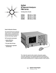
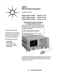
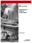
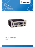
EE241-Introductory Electronics Laboratory
LAB 0-Familiarization to Lab Equipment
Purpose
The purpose of this lab is to give a brief review of the basic electronic components and electrical
equipment you have already used in PHY 110. During this lab we will discover resistors, capacitors and
operational amplifiers (as an instance of an IC). We will also learn how to use breadboard, function
generator, oscilloscope (or simply scope), digital multimeters (DMMs) and power supplies.
Resistors
A resistor is a two terminal passive electrical component. By passive it means that it does not require
external energy for its operation. When current passes through it, there is a voltage drop. The ratio
between voltage and current is known as electrical resistance (or simply resistance). The SI unit of
resistance is ohms (Ω).
Figure 1 shows a cartoon of a real resistor. The value of the resistance is represented by four color
bands. The value of each color according to its position (band) is summarized in Table 1.
Figure 1 A resistor
COLOR
1st Band
2nd Band
Black
Brown
Red
Orange
Yellow
Green
Blue
Violet
Gray
White
Gold
Silver
0
1
2
3
4
5
6
7
8
9
0
1
2
3
4
5
6
7
8
9
3rd Band
(multiplier)
x100
x101
x102
x103
x104
x105
x106
x107
x108
x109
X0.1
X0.01
4th Band
(Tolerance)
± 1%
± 2%
± 0.5%
± 0.25%
± 0.1%
± 0.05%
± 5%
± 10%
Note: Always read the resistance by positioning the resistor as shown in Figure 1 and reading from left
to right. For example, the value of resistor in Figure 1 is 02x103 ± 2% ohms.
For details, study Appendix A from “A First Lab in Circuit and electronics” by Y. Tsividis.
LUMS School of Science and Engineering, EE241-Fall ‘09. ©
1
Capacitors
The ability of a body to hold charge is called its capacitance. The capacitance (C) of a capacitor is the
measure of charge (Q) stored on each plate for a given potential difference or voltage (V) that appears
across the plates. The SI unit for capacitance is Farad (F). Figure 2 shows some common capacitor
models.
Figure 2 Different capacitor models
For details on this subject see Appendix A in “A First Lab in Circuit and electronics” by Y. Tsividis.
Operational Amplifiers
An amplifier is a device that uses a small amount of energy to control a larger amount. The relationship
of the input to the output (usually expressed as a function of the input frequency) is called the transfer
function of the amplifier, and the magnitude of the transfer function is termed the gain. Amplifiers are
typically utilized over a specific range of frequencies and are generally of maximal utility if the gain is
constant in that range. Operational amplifier (often called op-amp) is one of the most common types of
amplifiers1. Figure 3 shows the internal structure and pin configuration of the most commonly used IC
for op-amps (SN741).
Figure3 741 operational amplifier
The dot beside pin 1 is called the notch and represents the top side of an IC.
1
You will study the operation and applications of op-amp later in this course. They are merely discussed here to
give you a review of pin configuration of an IC.
LUMS School of Science and Engineering, EE241-Fall ‘09. ©
2
Breadboard
A breadboard is commonly used to make a prototype of an electronic circuit. The breadboard has many
strips of metal (copper usually) which run underneath the board. The metal strips are laid out as shown
in figure 5. These strips connect the holes on the top of the board. This makes it easy to connect
components together to build circuits. To use the bread board, the legs of components are placed in the
holes (the sockets). The holes are made so that they will hold the component in place. Each hole is
connected to one of the metal strips running underneath the board as shown in Figure 5.
Figure 4 Breadboard
SN741
SN741
Figure 5 Breadboard layout and IC placement
Figure 5 also shows the correct (and incorrect way) of placing an IC on the breadboard. A resistor should
be connected by placing each leg of the resistor in a different (shorted) row as shown in Figure 5. The
top and bottom rails of the breadboard are usually used for power supply connections.
LUMS School of Science and Engineering, EE241-Fall ‘09. ©
3
Function Generator
A simple function generator is a device that can produce periodic voltage signals of different frequencies
and amplitudes. In this lab Escort EGC-3230 function generator will be used. It will serve the purpose to
test the response of the circuits to common input signals. Signal from the function generator is being fed
into the circuit using coaxial cables.
*
For this lab, the most commonly used functions of EGC-3230 function generator are:
* Square wave - The signal goes directly from high to low voltage.
* Sine wave - The signal curves like a sinusoid from high to low voltage.
* Triangle wave - The signal goes from high to low voltage at a fixed rate.
Amplitude control - Varies the voltage difference between the high and low.
Frequency control – Adjusts the rate at which output signal oscillates.
Multimeter
A meter is a measuring instrument. An ammeter measures current, a voltmeter measures the potential
difference (voltage) between two points, and an ohmmeter measures resistance. A multimeter
combines these functions and possibly some additional ones as well, into a single instrument.
LUMS School of Science and Engineering, EE241-Fall ‘09. ©
4
Oscilloscope
An oscilloscope is used to visualize the time varying signals at different points in the circuit. In this lab
you are provided with Tektronix TDS 10002. You are encouraged to read its user manual to familiarize
with its basic operations.
Some basic operations which you will be using commonly in this lab are:
AUTOSET: Automatically sets the oscilloscope controls to produce a usable display of the input signals.
Each time you push the AUTOSET button, the Autoset function obtains a stable waveform display for
you. It automatically adjusts the vertical scale, horizontal scale and trigger settings.
AUTORANGE: Displays the Autorange Menu, and activates or deactivates the autoranging function.
Autorange is a continuous function that you can enable or disable. The function adjusts setup values to
track a signal when the signal exhibits large changes or when you physically move the probe to a
different point.
CURSOR: Displays the Cursor Menu. Cursors remain visible (unless the Type option is set to Off) after you
leave the Cursor Menu but are not adjustable.
This method allows you to take measurements by moving the cursors, which always appear in pairs, and
reading their numeric values from the display readouts.
MEASURE: Displays the automated measurements menu.
It can used to display the measurements and a MATH menu can be used to perform different arithmetic
operations between the two channels.
PRINT: Starts the print operation to a PictBridge compatible printer, or performs the SAVE function to
the USB flash drive.
SAVE: An LED indicates when the PRINT button is configured to save data to the USB flash drive
LUMS School of Science and Engineering, EE241-Fall ‘09. ©
5
DC Power Supply
A power supply provides a constant voltage to the circuit. In the lab you are provided with triple output
power supply with voltage and current display.
CAUTION: First turn ON the power supply and then gradually increase the output voltage otherwise
initial
al voltage overshoot can damage you circuit components.
LUMS School of Science and Engin
Engineering, EE241-Fall ‘09. ©
6
In Lab Practice
Experiment 3, steps 1- 17, pages 24-31
Mandatory Readings
“A First Lab in Circuit and electronics” by Y. Tsividis.
Good lab practices and other useful hints – pages 1-10
Ground Connections – pages 11-13
Experiments 1&2 – pages 14-23
Suggested Readings
User manuals of the scope, function generator, power supply and the multimeter.
LUMS School of Science and Engineering, EE241-Fall ‘09. ©
7