1
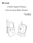
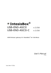
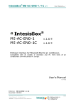
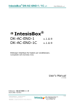
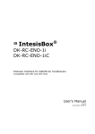
IntesisBox ® USB-ENO USB-ENO-C v.1.0.0 v.1.0.0 USB EnOcean gateway and repeater User's Manual r0 eng Issue Date: 07/02/2011 IntesisBox® USB-ENO / C © Intesis Software S.L. User’s Manual r0 eng All Rights Reserved. Information in this document is subject to change without notice. The software described in this document is furnished under a license agreement or nondisclosure agreement. The software may be used only in accordance with the terms of those agreements. No part of this publication may be reproduced, stored in a retrieval system or transmitted in any form or any means electronic or mechanical, including photocopying and recording for any purpose other than the purchaser’s personal use without the written permission of Intesis Software S.L. Intesis Software S.L. Milà I Fontanals, 1 bis, 1º 08700 Igualada Spain TRADEMARKS All trademarks and tradenames used in this document are acknowledged to be the copyright of their respective holders © Intesis Software S.L. - All rights reserved This information is subject to change without notice IntesisBox® is a registered trademark of Intesis Software SL URL Email tel http://www.intesis.com [email protected] +34 938047134 2 / 12 IntesisBox® USB-ENO / C User’s Manual r0 eng Gateway for integration of any EnOcean device in your USB enabled EnOcean compatible Controller or PC Software 2 models are available for this gateway, with the following Order Codes: USB-ENO EnOcean communication frequency: 868 MHz USB-ENO-C EnOcean communication frequency: 315 MHz © Intesis Software S.L. - All rights reserved This information is subject to change without notice IntesisBox® is a registered trademark of Intesis Software SL URL Email tel http://www.intesis.com [email protected] +34 938047134 3 / 12 IntesisBox® USB-ENO / C User’s Manual r0 eng INDEX 1. Presentation ................................................................................................... 5 1.1. Main Features: ................................................................................................. 5 1.2. Typical application ............................................................................................ 6 2. Connection and placement ................................................................................ 7 2.1. Connection ...................................................................................................... 7 2.2. Communication settings .................................................................................... 7 2.3. Placement ....................................................................................................... 7 2.2.1 Screening zones ...................................................................................... 7 2.2.2 Penetration Angle .................................................................................... 8 2.2.3 Use of repeaters ..................................................................................... 9 3. Configuration ................................................................................................ 10 3.1. Manual configuration ...................................................................................... 10 3.2. Commands configuration ................................................................................. 11 4. Technical data and dimensions ........................................................................ 11 5. Regulations and standards .............................................................................. 12 © Intesis Software S.L. - All rights reserved This information is subject to change without notice IntesisBox® is a registered trademark of Intesis Software SL URL Email tel http://www.intesis.com [email protected] +34 938047134 4 / 12 IntesisBox® USB-ENO / C User’s Manual r0 eng 1. Presentation Integration of any EnOcean device in your USB enabled EnOcean compatible Controller or PC Software IntesisBox® USB-ENO / C gateways allow supervision and bidirectional control of any Enocean device from PC systems such as SCADAs as well as any configuration and monitoring USB enabled systems. 1.1. Main Features: Bidirectional: Supervision and Control. Unlimited transmitters supported. Up to 128 actuators. ESP2 and ESP3 communication compatible. Compatible with remote management telegrams 1 & 2 level repeater functionality available. USB Powered. No external power supply needed. Plug and Play (virtual COM port). Suitable look for home applications. Small dimensions. © Intesis Software S.L. - All rights reserved This information is subject to change without notice IntesisBox® is a registered trademark of Intesis Software SL URL Email tel http://www.intesis.com [email protected] +34 938047134 5 / 12 IntesisBox® USB-ENO / C User’s Manual r0 eng 1.2. Typical application In Figure 1.1 it is shown a typical integration example using the USB-ENO / C to control and/or supervise IntesisBox® EnOcean AC Interfaces and many other devices. Figure 1.1 Integration example © Intesis Software S.L. - All rights reserved This information is subject to change without notice IntesisBox® is a registered trademark of Intesis Software SL URL Email tel http://www.intesis.com [email protected] +34 938047134 6 / 12 IntesisBox® USB-ENO / C User’s Manual r0 eng 2. Connection and placement 2.1. Connection 1. Plug the gateway to the USB port of the computer or control system. 2. The red USB LED (Figure 3.1) will turn on. Once the device has been recognized a virtual COM port is going to be generated and the LED will turn off. 3. To communicate with the gateway use this port. 2.2. Communication settings The IntesisBox ® USB-ENO / C can be configured to work with both ESP2 and ESP3. Detailed description of these protocols can be found in the EnOcean documentation. The following table is a summary of their properties and differences. Description Max. number of data types Max. size of transferred data [bytes] Data verification Communication speed [baud] ESP 2.0 7 28 Checksum 9600 ESP 3.0 255 65535 CRC8 57600 Table 2.1 ESP2 and ESP3 main properties 2.3. Placement The coverage distance (see Table 2.2) of the signal emitted by the USB-ENO-/ C, or by any other EnOcean device, is determined by the room geometry and where they are placed. As an example, long narrow corridors with wide walls are an adverse situation. People or other obstacles can reduce the coverage distance too. Is therefore advice to always think in the worst possible scenario to decide the placement of the device to ensure a good stability in the radio system. Conditions Line-of-sight connections Plasterboard walls / dry wood Brick walls / aerated concrete Ferroconcrete walls / ceilings Coverage distance typically 30 m range in corridors up to 100 m in halls typically 30 m range, through 5 walls typically 20 m range, through 3 walls typically 10 m range, through 1 ceiling Table 2.2 Device coverage distance 2.2.1 Screening zones It is important not to place the device in a place where the airwaves must go through a metallic object as they create a screening zone where the receivers are not going to be able to receive the EnOcean telegrams. This situation is shown in Figure 2.1a. © Intesis Software S.L. - All rights reserved This information is subject to change without notice IntesisBox® is a registered trademark of Intesis Software SL URL Email tel http://www.intesis.com [email protected] +34 938047134 7 / 12 IntesisBox® USB-ENO / C User’s Manual r0 eng Figure 2.1 a) Screening zone b) solution with a repeater The situation of one of the receivers doesn’t allow it to receive the transceiver telegrams. To solve this situation the use or a repeater outside the screening zone (Figure 2.1b) is recommended. The telegrams will be retransmitted from there to the receiver 2.2.2 Penetration Angle This is the angle in which the airwaves reach a certain object they need to go through. The transmission to the other side of the object would be better as this angle gets closer to 90 º, being this the best transmission situation In Figure 2.2a it is shown a receiver in a situation where the penetration angle is too close to 0º. The solution to that problem can be seen in Figure 2.2b using a repeater in a different position Figure 2.2 Penetration angle © Intesis Software S.L. - All rights reserved This information is subject to change without notice IntesisBox® is a registered trademark of Intesis Software SL URL Email tel http://www.intesis.com [email protected] +34 938047134 8 / 12 IntesisBox® USB-ENO / C User’s Manual r0 eng 2.2.3 Use of repeaters In case of a poor radio reception, it may be helpful to use a repeater. EnOcean repeaters do not require any configuration, only a line-power supply is needed. A poor radio signal is received, refreshed and transmitted again, so nearly a double radio range can be achieved. Special EnOcean repeaters which can be switched to 2-level function allow two repeaters to be cascaded. The USB-ENO / C can be configured to work as one (see section 3 for details). © Intesis Software S.L. - All rights reserved This information is subject to change without notice IntesisBox® is a registered trademark of Intesis Software SL URL Email tel http://www.intesis.com [email protected] +34 938047134 9 / 12 IntesisBox® USB-ENO / C User’s Manual r0 eng 3. Configuration In Figure 3.1 a schematic of the device can be seen. This is useful to follow the instruction in section 3.1 USB-ENO-v10-REV0 Intesis software Antenna PB1: Button ROT1: Configuration selector PB1 ROT1 MOD1 MOD1: Enocean module enocean ® 0 1 EF 2 D 3 C 4 B 5 A 6 9 8 7 CON1: USB connector USB LED: USB LED (red) COMM LED CONF LED: Configuration LED (red) NOT LED USB LED COMM LED: communication LED (green) CON1 Figure 3.1 Device diagram Two different configuration modes can be used: Manual or by commands (either using ESP2 or ESP3). Each way of configuring the gateway has different capabilities that can be seen in Table 3.1: Parameter BASE ID Repeater mode Protocol selection ESP 2.0 Yes No No ESP 3.0 Yes Yes No Manual No Yes Yes Table 3.1 Configuration modes 3.1. Manual configuration The manual configuration uses PB1 and ROT1 in Figure 3.1. Set the desired selector position in ROT1 (details in Table 3.2) and press the button PB1 during 5 seconds to execute the configuration order. Once the configuration is changed the CONF LED blinks as confirmation. Parameter Repeater mode Protocol selection ROT1 Selector position 0 1 2 A B Description Repeater disabled (Default value) 1- Level repeater 2- Level repeater ESP 3.0 (Default value) ESP 2.0 Table 3.2 Selector position and behavior © Intesis Software S.L. - All rights reserved This information is subject to change without notice IntesisBox® is a registered trademark of Intesis Software SL URL Email tel http://www.intesis.com [email protected] +34 938047134 10 / 12 IntesisBox® USB-ENO / C User’s Manual r0 eng 3.2. Commands configuration The commands to execute the supported functionalities explained in Table 3.1 are listed in the following table: Operation Set BASE ID Read BASE ID Get firmware version Set repeater functionality Get repeater functionality status ESP2.0 SET_BASEID RD_BASEID RD_SW_VER ----- ESP3.0 CO_WR_IDBASE CO_RD_IDBASE CO_RD_VERSION CO_WR_REPEATER CO_RD_REPEATER Table 3.3 Configuration commands More information about how to use this commands can be found in the documentation of communication protocols ESP2.0 and ESP3.0. 4. Technical data and dimensions The main features of the devices USB-ENO / C are shown in Table 4.1. For further detail check the USB-ENO / C datasheet Dimensions Weight Operating Temperature Stock Temperature Operating Humidity Stock Humidity Power requirements EnOcean Frequencies 71 x 71 x 27 mm 60 g -25 . . . 85ºC -40 . . . 85ºC <93% HR, non-condensing <93% HR, non-condensing USB powered. USB limitations apply USB-ENO: 868 MHz USB-ENO-C: 315 MHz Table 4.1 Technical data © Intesis Software S.L. - All rights reserved This information is subject to change without notice IntesisBox® is a registered trademark of Intesis Software SL URL Email tel http://www.intesis.com [email protected] +34 938047134 11 / 12 IntesisBox® USB-ENO / C User’s Manual r0 eng 5. Regulations and standards CE conformity: R&TTE EU-directive on Radio and Telecommunications Terminal Equipment The general registration for the radio operation is valid for all EU countries as well as for Switzerland. Standards: UNE-EN UNE-EN UNE-EN UNE-EN 50491-3:2010 60950-1:2007 61000-6-2:2006 61000-6-3:2007 FCC ID: SZV-STM300C IC: 5731A-STM300C The enclosed device complies with Part 15 of the FCC Rules. Operation is subject to the following two conditions: (i.) this device may not cause harmful interference and (ii.) this device must accept any interference received, including interference that may cause undesired operation. Warning: Changes or modifications made to this equipment not expressly approved by Intesis Software may void the FCC authorization to operate this equipment. © Intesis Software S.L. - All rights reserved This information is subject to change without notice IntesisBox® is a registered trademark of Intesis Software SL URL Email tel http://www.intesis.com [email protected] +34 938047134 12 / 12