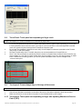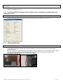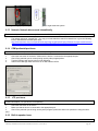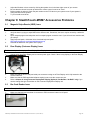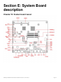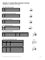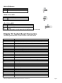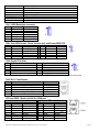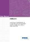
1
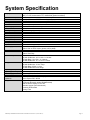
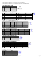
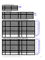
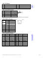
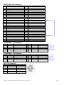
User Manual
StealthTouch-M5/M7 with
ATOM Dual Core models
StealthTouch-M5 part number
“GM…..”
“GA…..”
“GQ…..”
StealthTouch-M7 part number
“GD…..”
“GP…..”
If you need further assistance, use one of the following:
Website:
http://www.pioneerpos.com
(Download VGA, Network, Audio, Touch screen, & OPOS drivers. Obtain RMA Forms)
Pioneer POS Support line:
Call (909) 468-9757
Manual for StealthTouch-M5/M7 with Atom Dual Core model v1.1 (2013-04-17)
Page 1
Important Note
1) This manual is intended for StealthTouch-M5/M7 system with Serial Number starts with “5M” and “7M”.
2) This manual is intended for StealthTouch-M5/M7 system with Part Number:
StealthTouch-M5 part number
StealthTouch-M7 part number
“GM…..”
“GD…..”
“GA…..”
“GP…..”
“GQ…..”
Disclaimer
Information in this document is subject to change without notice. PioneerPOS shall not be liable for technical or editorial
errors in this document.
This manual contains proprietary information which is protected by copyright. No parts of this document may be
photocopied, reproduced, or translated to another language without prior written consent of Pioneer POS Solution, Inc.
Trademarks used in this manual:
PioneerPOS and PioneerPOS Logo are trademarks of Pioneer POS Solution, Inc.
Microsoft Windows, Windows are trademarks of Microsoft Corporation.
© 2012 Pioneer POS Solution, Inc. All rights reserved.
Target Audience
This Manual is written for technically qualified personnel. It is not intended for general audiences.
Warranty Exclusions
The warranty will not apply to damages caused by:
Unauthorized modification or abuse.
Improper or inadequate maintenance by customer.
Conventions
The following conventions are used in this manual:
[Warning]
A WARNING message indicates a potential for personal injury or death.
[Caution]
A CAUTION message indicates potential damage to hardware or loss of data
[Note]
A NOTE contains additional important information to help you in servicing the system.
Manual for StealthTouch-M5/M7 with Atom Dual Core model v1.1 (2013-04-17)
Page 2
Table of Contents
Table of Contents .................................................................................................................................................................. 3
Introduction ........................................................................................................................................................................... 4
About this guide .................................................................................................................................................................... 4
System Specification ............................................................................................................................................................ 5
Section A: Getting started with StealthTouch-M5/M7 system .......................................................................................... 6
Chapter 1: Identifying controls, ports, and peripherals ....................................................................................................... 6
Chapter 2: Setting up PioneerPOS system ......................................................................................................................... 9
Section B: Using StealthTouch-M5/M7 system ................................................................................................................ 15
Chapter 3: Touch screen panel ......................................................................................................................................... 15
Chapter 4: Network ........................................................................................................................................................... 16
Chapter 5: Serial port (RS232, COM ports) ...................................................................................................................... 18
Section C: Using StealthTouch-M5/M7 accessories ........................................................................................................ 20
Chapter 6: Using Customer Display/Rear Display (optional, part number “46B-RARJ”) .................................................. 20
Section D: Solving problems ............................................................................................................................................. 22
Chapter 7: Before working on your system ....................................................................................................................... 22
Chapter 8: StealthTouch-M5/M7 System Problems.......................................................................................................... 23
Chapter 9: StealthTouch-M5/M7 Accessories Problems .................................................................................................. 29
Section E: System Board description ............................................................................................................................... 30
Chapter 10: System board layout...................................................................................................................................... 30
Chapter 11: System Board jumper settings ...................................................................................................................... 31
Chapter 12: System Board Connectors ............................................................................................................................ 32
Manual for StealthTouch-M5/M7 with Atom Dual Core model v1.1 (2013-04-17)
Page 3
Introduction
PioneerPOS StealthTouch-M5/M7 system is a touch screen system that is a perfect fit for space-constrained applications
such as restaurant, hospitality, information service, medical, and the likes. PioneerPOS manufactures All-in-One touch
screen systems with built-in PC, as well as touch monitor with different sizes.
About this guide
This manual is intended to be use as a reference for field service as well as workshop repair. It is prepared to our best to
represent the current version of our production. In our effort to continuously our product, there may be changes that are
not represented in this manual. Please contact us directly if further assistance is required.
Please have the Serial Number and Part Number Ready before contacting our support line so they can assist you
efficiently.
Manual for StealthTouch-M5/M7 with Atom Dual Core model v1.1 (2013-04-17)
Page 4
System Specification
Display
Touch Screen Option
Processor
Memory
Storage
CD/DVD
Operating System
Network/Ethernet
Wi-Fi (wireless)
Serial Port
USB 2.0
PoweredUSB, +12 volts
PoweredUSB, +24 volts
Parallel Port
Cash Drawer Port
Compact Flash Reader
Speakers
Mounting Options
Security Lock
Bezel Color
Dimensions (with Base)
Weight
Operating Temperature
Operating Humidity
Power Supply
Agency Approvals
Built-in Printer
(optional)
Integrated Add-ons
(M5) 15” LCD, Active matrix TFT, 1024 x 768 (optimal resolution)
(M7) 17” LCD, Active matrix TFT, 1280X1024 (optimal resolution)
Resistive, Intellitouch SAW, Infrared, 3M Capacitive
Intel Atom Processor D2700
512MB, Maximum memory support: 4GB SODIMM
Hard Drive, Solid-state Disk, or Compact Flash
Internal (optional)
XP Prof, WePOS, POS Ready, XP embedded, Windows 7, Linux
10/100/1000 BaseT
RF 802.11 a/g/n (optional)
4
6
1
1
Optional
1 (can be connected to 2 cash drawers with adapter cable)
Optional
2 Watts, Stereo (optional)
Standard: Desktop Base
Option: Wall or VESA mount (please call for part#)
Bolted (4mm screw), or Kensington MicroSaver
Standard: Black
Option: Dark Grey
M5 with Base: 14.6 x 14.4 x 10.4 inches
M5 with Wallmount: 14.6 x 14.4 x 3.3 inches
M7 with Base: 16 x 15.4 x 11.4 inches
M7 with Wallmount: 16 x 15.4 x 3.5 inches
M5 With Base: 22 lbs / 10 kgs
M5 with Wallmount: 11 lbs / 5 kgs
M7 with Base: 25 lbs / 11 kgs
M7 with Wallmount:13 lbs/ 6 kgs
0C to 40C
20% to 80%
External, 150W, AC 100-240V
FCC A, CE
3” Thermal, 23 lines/sec, 80mm paper
Driver: Epson ESC, OPOS
Magnetic stripe or Barcode slot reader
Fingerprint /Biometric reader (DigitalPersona)
Rear customer display or 10" LCD
Barcode scanner (omni-directional)
Proximity RFID reader
Privacy Filter
Manual for StealthTouch-M5/M7 with Atom Dual Core model v1.1 (2013-04-17)
Page 5
Section A: Getting started with
StealthTouch-M5/M7 system
Chapter 1: Identifying controls, ports, and peripherals
1.1
Identifying controls and ports
Front View
System Power Indicator
Left View
CF Slot
Side USB
Slot
Right View
Card Reader
Port
(Optional)
Finger Print
Reader Port
(Optional)
I/O Panel View
Manual for StealthTouch-M5/M7 with Atom Dual Core model v1.1 (2013-04-17)
Page 6
I/O Ports
On / Off
Switch
Speaker
(Optional)
CD-RW /
DVD-RW
(Optional)
I/O Ports
Power
Input
(24V)
Power
Output
COM3
COM4
COM1
COM2
E-SATA
Port
PS/2
Keyboard
Cash
Drawer
USB
VGA
USB
LAN
Powered
USB
12V
Powered
USB
24V
Power Supply Unit (AC Adapter)
Part Number
“STLHPSFSP150”
Description
Dimension: 171mm x 40mm x 72 mm
Output DC Cable Length: 1.8m
Power LED
Power Input
Power Output
Max Power
Illustration
: YES (blue)
: AC 100-240V, 2A, 50-60Hz
: DC Power 24V, 6.25A
: 150W
Manual for StealthTouch-M5/M7 with Atom Dual Core model v1.1 (2013-04-17)
Page 7
Power
Supply Unit
LED Light
Power
Supply Unit
LED Light
Common Add-on Peripherals:
MSR (Magnetic Card Reader)
Magnetic card reader, Track 1-2, Keyboard Wedge.
Part Number: 46-D21000
MSR (Magnetic Card Reader) and/or Fingerprint Reader
Part Number: 46-D21F01
Customer Display
Integrated Rear Customer Display
Part Number: 46-RARJ-XXX (XXX: Emulation)
Manual for StealthTouch-M5/M7 with Atom Dual Core model v1.1 (2013-04-17)
Page 8
Chapter 2: Setting up PioneerPOS system
2.1
Connecting power
If your system comes with a base, you just need to locate the power cord and plug it to a surge protector or uninterruptible
power supply (UPS) Unit.
[Caution] Do not plug in the unit directly into a wall outlet. Lightning or power surge may damage the system. Always
connect the power through a surge protector or uninterruptible power supply (UPS) unit.
2.2
Connecting cables to I/O panel
1.
Tilt the terminal, then remove one Phillips M3 x 6 Big-Cap Black (P/N: 10-S3006BB) screw.
2.
Pull I/O Port Cover outward.
M5
M7
3.
Gently pull the base back cover outward.
[Note] If there are optional screws at both sides of the base back cover, remove them.
4.
5.
Route cables of peripherals to the front.
Connect cables to respective ports.
Manual for StealthTouch-M5/M7 with Atom Dual Core model v1.1 (2013-04-17)
Page 9
I/O Ports
6.
7.
Install I/O Panel Cover and Base Back Cover.
Press Power Switch to turn on the system.
2.3
Connecting network
The LAN network port is located on the I/O Panel. StealthTouch-M5/M7 also comes with optional build-in wireless LAN.
2.4
Installing card reader and/or finger print reader (optional)
1.
Remove 2 screws (see circles) to access port for Card/Finger Print reader.
2.
Connect cables(s) to respective port(s)
3.
Attached the reader to the main unit
Manual for StealthTouch-M5/M7 with Atom Dual Core model v1.1 (2013-04-17)
Page 10
4.
Secure the readers with two Phillips M3 x 14 Big-Cap White (P/N: 10-S3014BW) screws.
2.5
Installing customer display/rear display (optional)
1.
Tilt terminal, and pull the back cover upwards to open.
2.
Install the rear display to the unit, secure it with five Phillips M4 x 8 Big-Cap Black (P/N: 10-S4008BB) screws.
3.
Connect the Ext DC Plug Power Cable 12V (P/N: 34-319-122155) to the Molex Connector of SATA & Molex 4-Pin
Power Adapter (60CM) cable (P/N: 35-M5-319L60).
Manual for StealthTouch-M5/M7 with Atom Dual Core model v1.1 (2013-04-17)
Page 11
4.
Connect the Ext DC Plug Power Cable 12V (P/N: 34-319-122155) to the connector on the Rear Display unit.
5.
Tilt the unit and remove the I/O Panel cover (see arrow).
6.
Route the Rear Display’s cable to the front
7.
Connect the display’s cable to COM port.
I/O Ports
Manual for StealthTouch-M5/M7 with Atom Dual Core model v1.1 (2013-04-17)
Page 12
8.
Install the I/O Panel Cover back and secure it with one Phillip M3 x 6 Big-Cap Black (P/N: 10-S3006BB) screws.
9.
Cut the cable slot on back cover (see arrow).
10.
Install back cover to the Base.
2.6
Installing wall mount/VESA mount (optional, for VESA 75 Pole only)
Package Overview:
Wall Mount bracket [#16-M5-101] -----------1 pcs
2. 3x6, Black screw [10-S3006BB] -------------2 pcs
3. 4x8, Black screw [#10-S4008SB] -----------3 pcs
2.6.1 Wall mount
Manual for StealthTouch-M5/M7 with Atom Dual Core model v1.1 (2013-04-17)
Page 13
2.6.2 VESA 75 mount
Manual for StealthTouch-M5/M7 with Atom Dual Core model v1.1 (2013-04-17)
Page 14
Section B: Using StealthTouchM5/M7 system
Chapter 3: Touch screen panel
[Note] The instructions below apply for Resistive Type Touch Panel only. For other types of Touch Panels (Infrared,
Capacitive, SAW), please contact PioneerPOS Technical Support.
StealthTouth-M5/M7’s Touch Screen can be operated with finger or soft stylus. If you have re-installed the driver software,
you need to open TouchKit to re-calibrate the touch screen:
1.
2.
Go to Start -> All Programs -> eGalaxTouch -> Configure Utility.
Click on “Tools” when you need to calibrate.
3.
Perform 4 point calibration when you see the calibration screen. Use a touch screen stylus pen or your finger to
touch each point for about 1-2 seconds until you hear a “beep” sound.
[Note] Linearization is not needed for regular use.
Picture: 4 point calibration screen
Manual for StealthTouch-M5/M7 with Atom Dual Core model v1.1 (2013-04-17)
Page 15
Chapter 4: Network
4.1
Wired network
Standard StealthTouch-M5/M7 comes with on-board Intel Network controller. For regular network usage, you just need to
plug in the network cable and it should work. In case you need to check your network setting, you can follow the
instruction below:
1.
2.
3.
Start -> Control Panel -> System
Under “Hardware Tab”, select “Device Manager”
Expand “Network adapters” selection.
4.
In “Intel 82574L Gigabit Network Connection Properties”, you can check items such as: MAC Address, IP Address,
Link Status.
Manual for StealthTouch-M5/M7 with Atom Dual Core model v1.1 (2013-04-17)
Page 16
5.
To perform Network Test and Diagnostic under the table “Link Speed”. Then, click on “Diagnostics”.
4.2
Wireless network
4.2.1
For system installed with Intel MiniPCI/MiniPCI-E wireless card
1.
2.
Go to Start -> Program -> Intel PROset Wireless.
Click on “Intel PROset Wireless” to setup wireless utility.
3.
You can also access “Intel PROSet Wireless Utility” by double clicking the “Intel PROSet Wireless Utility” task tray
icon on the notification area on taskbar (see picture below). The icon gives us visual indication of the current
wireless connection state.
Manual for StealthTouch-M5/M7 with Atom Dual Core model v1.1 (2013-04-17)
Page 17
Chapter 5: Serial port (RS232, COM ports)
5.1
Serial port location and pin assignment
StealthTouch-M5/M7 comes with four RS232 Serial port on I/O Panel. The serial ports are using 8-Pin RJ45 connector.
Picture: Serial Port (RS232) Location
I/O Ports
Power
Input
(24V)
Power
Output
COM3
COM1
E-SATA
Port
Cash
Drawer
PS/2
Keyboard
USB
USB
COM4
COM2
VGA
LAN
Powered
USB
12V
Powered
USB
24V
Table: Pin Assignment for RS232 Serial Port
PIN
1
2
3
4
Serial Port Signal
DCD
RX
TX
DTR
5
6
7
8
GND
DSR
RTS
CTS
5.2
Description
Data Carrier detect
Receive data
Transmit data
Data Terminal
Ready
Signal Ground
Data Set Ready
Request to send
Clear to send
Using RJ45 to DB9 adapter with serial port/COM port
If you are using devices with DB9 Connector, you can use RJ45 to DB9 adapter. Please see picture below:
Picture: RJ45 Male to DB9 Male adapter (P/N: 30-326F)
Manual for StealthTouch-M5/M7 with Atom Dual Core model v1.1 (2013-04-17)
Page 18
Table: Pin assignment for RJ45 Male to DB9 Male adapter (P/N: 30-326F)
RJ45 Male
DB 9 Male
Pin 1
Pin 2
Pin 3
Pin 4
Pin 5
Pin 6
Pin 7
Pin 8
Pin 9
5.3
Pin 1 (Data carrier detect)
Pin 2 (Receive data)
Pin 3 (Transmit data)
Pin 4 (Data Terminal Ready)
Pin 5 (Signal ground)
Pin 6 (Data set ready)
Pin 7 (Request to send)
Pin 8 (Clear to send)
---
Power supplied by serial port/COM port
By default, COM Port 2 does not supply power. It can be set to supply +5V or +12V power by modifying jumper setting on
JP14 on the System Board. Please see table below for JP14 jumper setting. Power will be available on Pin 1.
[Warning] If you set COM Port 2 with power, remember to put a warning label on the I/O Panel so that users will not plug
in other devices to that port.
JP14: COM2 Power Select
JP14
COM 2
JP14
DCD PIN
1-3
+5V
2-4
3-5
+12V
4-6
7-9
DCD
8-10
COM 2
RI PIN
+5V
+12V
RI
[Note] The setting only affects COM2 port on I/O Panel. It does not affect internal I-COM2 Port on the
motherboard.
Manual for StealthTouch-M5/M7 with Atom Dual Core model v1.1 (2013-04-17)
Page 19
Section C: Using StealthTouchM5/M7 accessories
Chapter 6: Using Customer Display/Rear Display (optional,
part number “46B-RARJ”)
Unless specified, standard Rear Display/Customer Display shipped from PioneerPOS is set to AEDEX protocol by default.
6.1
Protocol/emulation supported
Pioneer POS rear display/customer display supports a few different protocols. The supported protocols are:
General
AEDEX
UTC standard
UTC Enhanced
Epson
CD7220 (CD5220-II)
PD3000
6.2
Reprogram rear display protocol/emulation
Please obtain the utility to reprogram Rear Display Protocol by contacting PioneerPOS Technical Support.
If you need to re-program the rear display firmware, you may connect the display to COM1/COM2/COM3/COM4 or COM5.
After that, run the “PPOSx.EXE” (x stands for version number, for example: “PPOS4.exe”) utility. Please follow the steps
below when after PPOS program is loaded:
1.
Enter the Com port that is connected to your rear display (You can choose COM1, COM2, COM3, COM4, or
COM5).
2.
Please input Command code number for the protocol that you wish to change to at the text filed after the line
“Please Input Command Code Number”.
Manual for StealthTouch-M5/M7 with Atom Dual Core model v1.1 (2013-04-17)
Page 20
3.
On the next field, “Please Input Scroll Data (Max 40 Byte for ASCII)”, you may leave the field blank or you can
type any sentence you would like for the scroll data.
4.
When you are ready, click “Write to EEPROM(Y)”
5.
A new pop up window will show up. The new emulation is being written to the rear display.
6.
You may now verify the new emulation by viewing at the Rear Display.
Manual for StealthTouch-M5/M7 with Atom Dual Core model v1.1 (2013-04-17)
Page 21
Section D: Solving problems
Chapter 7: Before working on your system
Before performing repairing/replacement procedure, please make sure that you read the safety information with each
system or part. Below are some information that is important to your safety and your system’s safety:
[Note] Only authorized technician trained by PioneerPOS should repair this system. Damage due to servicing not
authorized by PioneerPOS is not covered by your warranty. Do not try to repair at the component level such as Printed
Circuit Board (PCB), LCD Panel Unit, Inverter board, or Power Supply unit because it may cause safety hazard.
Modification of PCB such as motherboard may void the warranty that came with the component and the system.
7.1
Record keeping
1.
2.
3.
4.
Keep a paper to record of serial number/part number of units and any changes you made.
If you see an error message, write down the exact message on a piece of paper.
If you have a digital camera, take a picture of the error message on the system. Some issues may be intermittent.
Use a digital camera to take a picture before disassembling the system or removing parts. You will be able to see
how the cables are routed. Record the existing jumper setting and connector settings on your system.
7.2
Protecting your own safety
1.
2.
3.
Unplug power from AC power source if you need to disassemble the system.
Protect your own safety with insulating glove.
[Warning] To prevent electric shock, DO NOT open up Power Supply Unit, CRT Monitor Unit.
7.3
Protecting your data
1.
2.
3.
Make sure that you have backed up important data. You may also create a backup image of your system.
You may back up important data on a USB Memory Drive.
If you have important system settings such as password, make sure you keep your password in a safe place.
7.4
Removing power source
1.
2.
3.
Remove power source before you try to remove any parts.
Turn off the system and unplug the power from the wall.
Remove any attached device with power connected to them such as LTP Printer, USB Hubs.
7.5
Electrostatic discharge (ESD)
1.
2.
3.
[Caution] Electrostatic discharge (ESD) could permanently damage the electronic components in your system.
Always ground yourself with a wrist grounding strap.
Periodically touch an unpainted metal surface to avoid electrostatic discharge.
7.6
Handling cables and connectors
When you need to disconnect cables at COM Port, LAN port, LTP port, VGA port, Power Connector, or connectors on
MSR, do not pull the cable itself. Please remove the connector from the socket carefully. If they have a locking tab (LAN
port, COM Port), press and hold the plastic locking tab while removing the connector.
When removing the connector on motherboard, look for the location of “Pin1”. Make sure that you put the connector back
with the same way before removing it to avoid short circuit. You make take a picture of the original connectors with a
digital camera before removing it from the System Board.
Manual for StealthTouch-M5/M7 with Atom Dual Core model v1.1 (2013-04-17)
Page 22
7.7
Handing components
When handling CPU, memory, or hard drive, do not touch the connection surface. Hold the component by its edge and do
not hold the contact part.
Chapter 8: StealthTouch-M5/M7 System Problems
8.1
No power
Problem description: System could not turn on (no POST screen, System Power Indicator LED is off, no sound from Fan
or Hard Drive).
1.
Make sure that the power cord coming out from the system is plugged in to the power source (electrical outlet). By
pass power strips or power extension or UPS (Uninterrupted Power Supply) to verify that the system turns on.
Verify that the electrical outlet is working by connecting it to equipment such as a radio.
Check if the LED light on Power Supply Unit is on. If it is not on, double check the connection of power chord to
the Power Supply Unit.
2.
Power
Supply Unit
LED Light
Power
Supply Unit
LED Light
3.
Make sure that the power cord is plugged in to the power supply block completely.
3.
4.
Check if you have the right power adapter. Power adapter part number are STLH-PSFSP150 or STLH-PSFSP120.
Make sure that the power connector is plugged in to the power port on I/O panel. Unplug and re-connect the
power connector as required.
5.
A defective hard drive my cause the system to not able to boot. Please refer to “Hard Drive Issue”
8.2
“Invalid System Disk” message
Problem description: While the system is booting, you receive the following error message:
Invaid System disk
Replace the disk, and then press any key
Manual for StealthTouch-M5/M7 with Atom Dual Core model v1.1 (2013-04-17)
Page 23
1.
2.
3.
4.
Double-check the Boot Device Priority under Boot Option in BIOS setup utility.
Double-check if connectors on hard-drive are connected properly.
The system may be infected with a boot-sector virus. Run a virus check on the hard drive.
You may also check if hard drive is detected by pressing F11 when the system is booting up. Make sure that the
main hard drive is shown in "Select Boot Device" screen. If hard drive is detected, please try reinstalling or reimaging O/S to the hard drive.
8.3
System keeps restarting
Problem description: System keeps restarting by itself
1.
If the system keeps booting to windows and keep restarting by itself, please check if you have a virus on the
system. You may replace another hard drive. Then, you may check for viruses on the original hard drive.
2.
If the system keep restarting before it is able to load Operating System, please check if power supply unit is
working. If you have another spare power supply unit, please test the system with a spare power supply unit.
8.4
System is on but there is no display on LCD monitor
Problem description: You can hear system boots to OS successfully. You could hear “beeps” when you touch the touch
screen panel. The System Power Indicator LED is on. However, the LCD has no display.
1.
2.
3.
8.5
Please shut down the system and restart the system again.
If you could see POST Screen, the problem may be caused by improper setting in Display Driver. Follow the
following steps to get into Window’s “safe mode” to uninstall display driver.
a.
You could switch off the system manually by pressing the on/off button.
b.
After that, turn on the system again. Start tapping the F8 key repeatedly.
[Note: Sometimes computer may display a “keyboard error” message if you begin tapping the F8 key too
early. To resolve this issue, please restart the system and try again.]
c.
You will see a screen with “Windows Advanced Option Menu” with dark background after the boot up
screen.
d.
Please select “Safe Mode” option by using the up/down key
e.
Then, select “Microsoft Window XP Professional” or your installed Windows operating system if you are
given a choice.
e.
Login to Administrator or any user to get on to Desktop.
f.
Click “Yes” when you see a Warning Box with message “Windows is running in safe mode…”
g.
You are now in Safe Mode.
h.
Please uninstall VGA driver in by uninstalling VGA driver from “Add/Remove Programs” or remove VGA
driver from Device Manager.
g.
Restart the computer and re-install VGA driver again.
If you could not see POST screen, try to connect an external monitor to the VGA connector on I/O Panel. If you
could see display from external monitor, the problem could be caused by defective inverter board or LCD. Please
contact PioneerPOS Technical Support.
Software or POS application/program stops responding
Problem description: Certain running program/POS application stops responding. Operating system is still working.
1.
2.
3.
4.
5.
8.6
Please contact your POS application or program technical support if they freeze up periodically and everything
else are working.
You may use a keyboard and press <ctrl><alt><delete> to go to “Windows Task Manager”.
Click on “Applications” tab.
Select the program that is not responding.
Click “End Task”. Please understand that when a program stops responding, any work that has not been saved
will may be lost when we end a program using task manager.
Operating system not responding/solid Blue Screen with error message
Manual for StealthTouch-M5/M7 with Atom Dual Core model v1.1 (2013-04-17)
Page 24
Problem description: Operating system not responding to touch. You may see a solid blue screen with error message
sometimes.
1.
2.
3.
4.
If the computer stops responding with finger touch, double-check if the problem is caused by touch panel issue.
Try to plug in a USB mouse or keyboard to see if you get the system to work. If you verify that it is Touch Panel
issue. Refer to the section “Touch Panel: Touch Panel not responding to finger touch”.
Use a digital camera or pen to record any error message. Then, press and hold the power switch for at least 5
seconds. This will shut down the system. Please understand that when a program stops responding, any work
that has not been saved will may be lost when we shut down the system.
Restart the computer again.
A bad sector on hard drive may cause system to freeze or “Blue Screen” if you are using Windows. Try to use
Windows Check Disk to check if your system has a bad sector.
To further diagnose the issue, you may install hard drive’s utilities depending on the brand of the hard drive in the
system. For example, if you are using Western Digital hard drive, you may use “Data Lifeguard Tools” available at
Western Digital Support Website.
Western Digital: Western Digital Data Lifeguard Tools for Windows/Dos
http://support.wdc.com/product/download.asp?level1=6&lang=en
Select any Hard Drive listed in SATA I, then select “Data Lifeguard Tools” for Windows or DOS.
Hitachi
http://www.hitachigst.com/hdd/support/download.htm
Fujitsu: Windows Diagnostic Tool/DOS Diagnostic Tool
http://www.fujitsu.com/us/services/computing/storage/hdd/support/utilities.html
If you found bad sector on the hard drive, please contact PioneerPOS Technical Support for replacement of hard
drive with correct technical spec.
8.7
Touch panel: Touch position is not accurate
Problem description: Touch position is not accurate.
If touch position is not accurate, then try launch Touckit utility to re-calibrate by following the steps below:
1.
2.
Go to Start -> All Programs -> eGalaxTouch -> Configure Utility.
Click on “Tools” when you need to calibrate.
3.
Perform 4 point calibration when you see the calibration screen. Use a touch screen stylus pen or your finger to
touch each point for about 1-2 seconds until you hear a “beep” sound.
[Note] Linearization is not needed for regular use.
Manual for StealthTouch-M5/M7 with Atom Dual Core model v1.1 (2013-04-17)
Page 25
8.8
Touch Panel: Touch panel not responding to finger touch
Problem description: The cursor on Windows is not activated by finger touch.
1.
2.
3.
4.
8.9
Try to use a keyboard/mouse to test if the system has lockup problem (system stops responding). If you are able
to use keyboard/mouse to move the cursor, go to step 2. If you are not able to use mouse/keyboard to activate
cursor, the system may have lockup problem. Restart the computer again.
Be sure that Touch adapter is detected in touch utility. If touch adapter not detected, press Add on the Touchkit
utility screen to add touch adapter.
Re-install Touchkit utility driver. TouchKit utility driver can be downloaded from PioneerPOS.com.
Since Touch Panel Controller is controlled by Serial Controller on System Board, defective Serial Controller may
cause problem on Touch Panel. Please double-check device manager to see if you are having problem on COM
Ports. If COM Ports are having problem, you will see yellow exclamation mark in device manager under
“communication ports”.
Touch panel: Cursor always stay on the edge of the screen
Problem description: The touch active area on one side of the screen is pressed.
1.
2.
Check for any dirt/dust accumulation on the side of the screen; otherwise re-adjust the touch screen panel.
Make sure the active are around the touch panel is not pressed/touched by other objects.
8.10
Touch panel: Touch panel not responding to finger after updating Windows to Service
Pack 3 (SP3)
Manual for StealthTouch-M5/M7 with Atom Dual Core model v1.1 (2013-04-17)
Page 26
Problem description: After updating your system with Service Pack 3, the touch panel does not respond to finger touch
intermittently.
1.
Update TouchKit Driver to v5.1.xx
8.11 Touch Panel (IR Touch Panel): IR touch glass cursor responds to sunlight, dither and
moving on screen
Problem description: IR touch glass cursor responds to sunlight, dither and moving on screen.
1.
8.12
Enable touch delay option in IR Touch Screen Control Panel, set touch delay to 100, area to 5.
PS/2 keyboard issue
Problem description: PS/2 keyboard not responding.
1.
2.
Try to replace the original keyboard with a different keyboard to make sure that the issue is not caused by a
defective keyboard.
Since the data from the keyboard passes through MSR, a defective MSR will cause the keyboard to have problem.
You may detect this problem by removing MSR and then put 2 jumpers to the top 4 pin. Please contact
PioneeerPOS Technical Support if you have a defective MSR.
Manual for StealthTouch-M5/M7 with Atom Dual Core model v1.1 (2013-04-17)
Page 27
[Caution] If you put the jumper to the wrong pin, it might restart the system.
8.13
Network: Network disconnects intermittently
Problem description: Network intermittently disconnected. LAN is not working after system recovers from standby state
1.
The network chipset is “Intel 82574L”. You may go to Intel website to search for latest driver or go to the following
links to download and reinstall latest driver:
http://downloadcenter.intel.com/SearchResult.aspx?lang=eng&ProductFamily=Ethernet+Components&ProductLin
e=Ethernet+Controllers&ProductProduct=Intel%C2%AE+82574+Gigabit+Ethernet+Controller
8.14
COM port/serial port issue
Problem description: COM port/serial port device not responding
1.
2.
3.
4.
8.15
Check the connection of the device. Make sure the device is connected to the appropriate port.
Check if the particular port is currently being used by other program/printer.
Test the COM port with generic printer under Windows.
Under Device Manager make sure there is no IRQ address conflict
LTP port issue
Problem description: LTP port device not responding
1.
2.
3.
port).
Check the connection of the device.
Make sure that the device is connected to the appropriate port.
Check if the particular port is being used by other program (make sure that no two printers are using the same
8.16
Built-in speaker issue
Problem description: No sound from built-in speaker
Manual for StealthTouch-M5/M7 with Atom Dual Core model v1.1 (2013-04-17)
Page 28
1.
2.
3.
Adjust the Windows volume control by clicking the speaker icon in the lower-right corner of your screen.
Be sure that the volume is turned up and that the volume control is not set to "mute".
Built-in speaker is optional. Check the part number on the FCC label on your system to see if your system is
configured with built-in speaker.
Try to re-install sound driver.
Chapter 9: StealthTouch-M5/M7 Accessories Problems
9.1
Magnetic Stripe Reader (MSR) issue
Problem description: Magnetic Stripe Reader (MSR) cannot read cards.
1.
4.
Verify the issue by trying to swipe MSR with a different card. Sometimes, the issue may be caused by a defective
card.
Open notepad program and swipe the card in notepad program to test the card. If you still could not read the card,
go to step 3.
Apply keyboard patch, visit below link to download keyboard patch.
http://www.pioneerpos.com/download/kbdpatchxp.zip
Uninstall the MSR from the system and re-plug it.
9.2
Rear Display (Customer Display) issue
2.
3.
Problem description: No display on Rear Display, Rear Display does not display correct message
1.
Unplug power from Rear Display and re-connect power again. Check if there is any display on the Rear Display.
2.
Make sure that the RJ45 COM port/serial port connector coming out of Rear Display unit is fully inserted to the
correct COM Port.
Make sure that the POS application/software setting is set to use the correct com port.
Refer to Chapter 8: Using Customer Display/Rear Display (Optional, Part Number “46-RxRJ” only) if you
need to change the type of emulation on the Customer Display/Rear Display unit.
3.
4.
9.3
Bar Code Reader issue
Problem Description: Barcode reader not working
1.
Make sure that keyboard terminator is connector to PS/2 connector located on I/O panel
Manual for StealthTouch-M5/M7 with Atom Dual Core model v1.1 (2013-04-17)
Page 29
Section E: System Board
description
Chapter 10: System board layout
Manual for StealthTouch-M5/M7 with Atom Dual Core model v1.1 (2013-04-17)
Page 30
Chapter 11: System Board jumper settings
(Highlighted item indicates factory default setting)
JP3: LVDS LCD Power Select
JP3
1-2
2-3
LVDS Power
3.3V (default)
5V
JP4: LED and CCFL Inverter Select
JP4
1-2
2-3
LVDS Power
CCFL Inverter (default)
LED Inverter
JP9: COM 6 Power Select
JP9
1-2
2-3
COM 6 Power Select
+3.3V (default)
DCD
JP13: COM 2 RI Pin Select
JP13
1-2
2-3
COM 2 RI Pin Select
Ring
GND(default)
JP14: COM 2 Power Select
JP14 COM 2 DCD Pin (Pin 1)
JP14
1-3
+5V
2-4
3-5
+12V
4-6
7-9
DCD (default)
8-10
Note: The setting will not affect the I-COM2
COM 2 RI Pin (Pin 5)
+5V
+12V
RI (default)
JP17: Panel Type Selection for LVDS
JP17 Boot Display Device
1-2
3-4
Boot Display Device
Short
Short
N/A
Open
Short
LCD
Short
Open
CRT
Open
Open
LCD+CRT (default)
JP17 Panel Type Setting
5-6
7-8
Boot Resolution Select
Short
Short
1440 x900 / 1920 x 1080 (CH7511)
Short
Open
1280 x 1024
Open
Short
1024 x 768 (default)
Open
Open
800 x 600
Manual for StealthTouch-M5/M7 with Atom Dual Core model v1.1 (2013-04-17)
Page 31
CN24: LVDS Source
CN24
1-2
2-3
LVDS Source
Cedar View
CHRONTEL 7511 (Default)
CMOS1: Clear CMOS
CMOS1
1-2
2-3
Clear CMOS
Normal (Default)
Clear CMOS
KB1: PS/2 for MSR
KB1
PS/2 for MSR
None PS/2 MSR plugged
1-2
By pass PS/2 keyboard signal if MSR is not plugged.
3-4
(Default)
(Note: Need short-plug on pin-1&-2 and pin-3&-4 if MSR device is not connected)
Chapter 12: System Board Connectors
The following listed the function on each connector on the mother board
Connector name
CN1
CN3
CN4
CN5
CN7 and CN25
CN9
CN10
COM5
COM6
CPUFAN1
I-COM2
J4
J6
JLPC1
JLVDS2
JLVDS3
JSPI1
KB1
LAN1
LPT1
MPCIE1
POWERUSB1
POWERUSB2
PS2
PW1
PW3
PW5
PW6
SATA1
Definition
LVDS Backlight Connector
Side USB Header, Reset, Inverter Adj, and Power/HDD LED
Digital I/O (8bits)
RJ-11 Cash Drawer
Stack up RJ45 for COM port
RS422/485
MIC and Line-out pin header
Internal COM5 (RS-232 Level)
Internal COM6 (TTL Level)
CPU FAN header (3 PIN)
Internal COM2 connector
Power connector
ATX 2x2 R/A connector
Debug header
LVDS Data Connector Chrontel output- dual channel
JLVDS3: LVDS Data Connector Cedar View – single channel
SPI Header
Internal PS/2 interface
RJ45 for Ethernet
Parallel Port Header
Mini PCI-E Connector
+12 V USB port
+24 V USB port
PS/2 Connector
DC-in Connector(24V,4pin)
12V Power Connector
5V Power Connector
5V Power Connector
SATA Connector
Manual for StealthTouch-M5/M7 with Atom Dual Core model v1.1 (2013-04-17)
Page 32
SPK1
SPK2
SW1
TS1
USB1
USB_ESATA1
VGA1
VGA2
Speaker Output Header-L
Speaker Output Header-R
Power Switch Header
Touch Screen Connector
USB Interface MSR connector
USB and eSATA connector
VGA port (Internal connector)
VGA port
CN1: LVDS Backlight connector
Pin
1
2
3
4
5
6
Name
+12V
+12V
GND
Adjust
GND
ON/OFF
Signal
+V12S
+V12S
GND
INV_BL_CTRL
GND
LCD_ON/OFF
CN3: Side USB Header, Reset, Inverter Adj, and Power/HDD LED
Pin
1
3
5
7
9
11
Name
High
Adjust
Low
PWR LEDLED+(VCC)
HDD LED-
Signal
+V5S (1K)
LVDS_BL_CTRL
GND (1K)
GND
+V3.3S (330R)
HDLED#
Pin
2
4
6
8
10
12
Name
USB VCC
DATADATA+
GND
Reset
(KEY)
Signal
+V5DUAL
USB_P6USB_P6+
GND
RESET#
-
CN4: Digital IO (8 bits)
Pin
Signal Name
Pin
Signal Name
1
GND
2
+5V
3
GPIO_I0
4
GPIO_O_0
5
GPIO_I1
6
GPIO_O_1
7
GPIO_I2
8
GPIO_O_2
9
GPIO_I3
10
GPIO_O_3
Note: Do not use Digital IO on GPIO_I0, GPIO_O_0 and GPIO_O_1when Cash Drawer port is being used
CN5: RJ11 Cash Drawer
Pin
1
2
3
4
5
6
Name
GND
Cash Drawer 2 (Digital Output)
+24V
Drawer Open/Close Signal (Digital Input)
Cash Drawer 1(Digital Output)
GND
Signal
GND
DOOR_O_1
+24V_CS
DIO_I0
DOOR_O_0
GND
CN7 and CN25: Stack up RJ45 for COM port
Lower (COM1 & COM3)
Upper(COM2
Pin
Name
Signal
Pin
Name
1
DCD
NDCDA
1
DCD
2
RX
NSINA
2
RX
3
TX
NSOUTA
3
TX
4
DTR
NDTRA
4
DTR
5
GND
GND
5
RI
6
DSR
NDSRA
6
DSR
7
RTS
NRTSA
7
RTS
8
CTS
NCTSA
8
CTS
Note 1:COM2 is located on the upper side of CN7
Manual for StealthTouch-M5/M7 with Atom Dual Core model v1.1 (2013-04-17)
Note1
& COM4)
Signal
Note2
NDCDB_S
NSINB
NSOUTB
NDTRB
Note3
NRIB_P
NDSRB
NRTSB
NCTSB
Page 33
Note 2: (Applies to COM2 only) JP14 to select +5V, +12V or NDCDB
Note 3: (Applies to COM2 only) JP13 and JP14 to select +5V, +12V, NRIB or GND
CN9: RS422/485 for COM3
Pin
1
2
3
4
RS-422
RXTXRX+
TX+
RS-485
DataData+
CN10: MIC and Line-out pin header
Pin
1
3
5
Name
MIC-L
MIC-R
LINE-R
Signal
MIC2_L_L
MIC2_L_R
LINE2_L_R
Pin
2
4
6
7
9
JD-SEND
LINE-L
GND
LINE2_L_L
8
10
Name
GND
PRESENCE#
MIC-JDRETURN
(KEY)
LINE-JDRETURN
Signal
GND
NC
MIC2-JD
LINE2-JD
COM5 : Internal COM 5 (RS-232 Level)
Pin
1
3
5
7
9
Name
DCD
RX
TX
DTR
GND
Signal
NDCDE
NSINE
NSOUTE
NDTRE
GND
Pin
2
4
6
8
10
Name
DSR
RTS
CTS
RI
(KEY)
Signal
NDSRE
NRTSE
NCTSE
NRIE
NC
COM6 : Internal COM 6 (TTL Level)
Pin
1
3
5
7
9
Name
DCD
RX
TX
DTR
GND
Signal
COM6_DCDCOM6_SIN
COM6_SOUT
COM6_DTRGND
Pin
2
4
6
8
10
Name
DSR
RTS
CTS
RI
(KEY)
Signal
COM6_DSRCOM6_RTSCOM6_CTSCOM6_RINC
CPUFAN1: CPU FAN Header (3pin)
Pin
1
2
3
Signal Name
GND
+12 V
Tach
Description
Ground
PWM controlled pulses
FAN Tachometer
I-COM2: Internal COM2 connector*
Pin
1
3
5
7
9
Name
DCD
RX
TX
DTR
GND
Signal
NDCDE
NSINE
NSOUTE
NDTRE
GND
Pin
2
4
6
8
10
Name
DSR
RTS
CTS
RI
(KEY)
Signal
NDSRE
NRTSE
NCTSE
NRIE
NC
J4: Power connector
Pin
1
2
3
4
Name
GND
GND
+5V
+12V
Signal
GND
GND
+V5S
+V12S
Manual for StealthTouch-M5/M7 with Atom Dual Core model v1.1 (2013-04-17)
Page 34
J6: ATX 2X2 R/A connector
Pin
1
2
3
4
Name
GND
GND
+5V
+12V
Signal
GND
GND
+V5S
+V12S
JLPC1: Debug Header
Pin
1
3
5
7
9
11
Name
NC
AD3
AD1
FRAME#
KEY(Empty)
CLK
Signal
NC
LPC_AD3
LPC_AD1
LPC_FRAME#
KEY
CLK33M
Pin
2
4
6
8
10
12
Name
VCC
RESET#
AD2
AD0
GND
GND
Signal
+V3.3S
PLTRST#
LPC_AD2
LPC_AD0
GND
GND
JLVDS2: LVDS Data Connector Chrontel output- dual channel
Pin
1
2
3
4
5
6
7
8
9
10
11
12
13
14
15
Name
GND
GND
A_DATA3+
A_DATA3A_CLK+
A_CLKA_DATA2+
A_DATA2A_DATA1+
A_DATA1A_DATA0+
A_DATA0GND
GND
B_DATA3+
Signal
GND
GND
LVDS_L3_P_R
LVDS_L3_N_R
LVDS_CLKL_P_R
LVDS_CLKL_N_R
LVDS_L2_P_R
LVDS_L2_N_R
LVDS_L1_P_R
LVDS_L1_N_R
LVDS_L0_P_R
LVDS_L0_N_R
GND
GND
LVDS_U3_P_R
Pin
16
17
18
19
20
21
22
23
24
25
26
27
28
29
30
Name
B_DATA3B_CLK+
B_CLKB_DATA2+
B_DATA2B_DATA1+
B_DATA1B_DATA0+
B_DATA0GND
GND
VDD
VDD
VDD
GND
Signal
LVDS_U3_N_R
LVDS_CLKU_P_R
LVDS_CLKU_N_R
LVDS_U2_P_R
LVDS_U2_N_R
LVDS_U1_P_R
LVDS_U1_N_R
LVDS_U0_P_R
LVDS_U0_N_R
GND
GND
VCC_LVDS
VCC_LVDS
VCC_LVDS
Note
GND
JLVDS3: LVDS Data Connector Cedar View – single channel
Pin
1
2
3
4
5
6
7
8
9
10
11
12
13
14
15
Name
GND
GND
A_DATA3+
A_DATA3A_CLK+
A_CLKA_DATA2+
A_DATA2A_DATA1+
A_DATA1A_DATA0+
A_DATA0GND
GND
B_DATA3+
Signal
GND
GND
LVDS_TX3_DP
LVDS_TX3_DN
LVDS_CLK_DP
LVDS_CLK_DN
LVDS_TX2_DP
LVDS_TX2_DN
LVDS_TX1_DP
LVDS_TX1_DN
LVDS_TX0_DP
LVDS_TX0_DN
GND
GND
N/A
Pin
16
17
18
19
20
21
22
23
24
25
26
27
28
29
30
Name
B_DATA3B_CLK+
B-CLKB_DATA2+
B_DATA2B_DATA1+
B_DATA1B_DATA0+
B_DATA0GND
GND
VDD
VDD
VDD
GND
Signal
N/A
N/A
N/A
N/A
N/A
N/A
N/A
N/A
N/A
GND
GND
VCC_LVDS
VCC_LVDS
VCC_LVDS
Note
GND
Note: Must check this pin is GND or VDD before plug and older version LVDS cable.
Manual for StealthTouch-M5/M7 with Atom Dual Core model v1.1 (2013-04-17)
Page 35
JSP1: SPI Header
Pin
1
3
5
7
Signal Name
VCC3
SPI_CS#
SPI_MISO
HOLD#
Pin
2
4
6
8
Signal Name
GND
SPI_CLK
SPI_MOSI
Key
KB1: Internal PS/2 interface
Pin Name
Signal
Note
1
CLOCK IN
KCLK_IN
Note
2
CLOCK OUT
KCLK_OUT
Note
3
DATA IN
KDAT_IN
Note
4
DATA OUT
KDAT_OUT
5
GND
GND
6
VCC
+V5DUAL
(Note: Need short-plug on pin-1&-2 and pin-3&-4 if MSR device is not connected)
LAN1: RJ45 for Ethernet
Pin
Speed
LED
Activity
LED
1
2
3
4
5
6
7
8
Name
100M
1G
LED+
ACTIVE
LEDTD4TD4+
TD3TD3+
TD2TD2+
TD1TD1+
Signal
LAN1_LED100LAN1_LED1000LAN1_LINK_ACT
LAN1_ACTLEDLAN1_MDI3N
LAN1_MDI3P
LAN1_MDI2N
LAN1_MDI2P
LAN1_MDI1N
LAN1_MDI1P
LAN1_MDI0N
LAN1_MDI0P
LPT1: Parallel Port Header
Pin
1
3
5
7
9
11
13
15
17
19
21
23
25
Name
STB#
PD1
PD3
PD5
PD7
BUSY
SLCT
ERR#
SLIN#
GND
GND
GND
GND
Signal
LPT_STB#
LPT_PD1
LPT_PD3
LPT_PD5
LPT_PD7
LPT_BUSY
LPT_SLCT
LPT_ERR#
LPT_SLIN#
GND
GND
GND
GND
Pin
2
4
6
8
10
12
14
16
18
20
22
24
26
Name
PD0
PD2
PD4
PD6
ACK#
PE
AFD#
INIT#
GND
GND
GND
GND
(Key)
Manual for StealthTouch-M5/M7 with Atom Dual Core model v1.1 (2013-04-17)
Signal
LPT_PD0
LPT_PD2
LPT_PD4
LPT_PD6
LPT_ACK#
LPT_PE
LPT_AFD#
LPT_INIT#
GND
GND
GND
GND
Page 36
MPCIE1: Mini PCI-E connector
Pin
Signal Name
1
WAKE#
3
NC
5
NC
7
CLKREQ#
9
GND
11
CLK_MINICARD#
13
CLK_MINICARD
15
GND
Mechanical Key
17
NC
19
NC
21
GND
23
PERn0
25
PERp0
27
GND
29
GND
31
PETn0
33
PETp0
35
GND
37
GND
39
3.3VAUX
41
3.3VAUX
43
GND
45
Reserved
47
Reserved
49
Reserved
51
Reserved
Pin
2
4
6
8
10
12
14
16
Signal Name
3.3Vaux
GND
1.5V
NC
NC
NC
NC
NC
18
20
22
24
26
28
30
32
34
36
38
40
42
44
46
48
50
52
GND
W_DISABLE#
PERST#
3.3Vaux
GND
1.5V
SMB_CLK
SMB_DATA
GND
NC
NC
GND
NC
NC
NC
1.5V
GND
3.3VAUX
POWERUSB1: +12 V USB port
Pin
1
2
3
4
Name
VCC USB
DATADATA+
GND
Signal
+V5 DUAL
USB_P2USB_P2+
GND
Pin
5
6
7
8
Name
12V GND
12V_1
12V_2
12V GND
Signal
GND
+V12S
+V12S
GND
Pin
5
6
7
8
Name
24V GND
24V_1
24V_2
24V GND
Signal
GND
+V24S
+V24S
GND
POWERUSB2: +24 V USB port
Pin
1
2
3
4
Name
VCC USB
DATADATA+
GND
Signal
+V5 DUAL
USB_P1USB_P1+
GND
PS2: PS/2 connector
Pin
1
2
3
4
5
6
Name
DATA
NC
GND
VCC
CLK
NC
Signal
KBDATA
MSDATA
GND
+V5DUAL
KBCLK
MSCLK
Manual for StealthTouch-M5/M7 with Atom Dual Core model v1.1 (2013-04-17)
Page 37
PW1: DC-in Connector (4 pin)
Pin
1
2
3
4
Name
+24V
+24V
GND
GND
Signal
+V24IN
+V24IN
GND
GND
PW3: 12V Power Connector
Pin
1
2
Name
GND
+12V
Signal
GND
+V12S
PW5: 5V Power Connector
Pin
1
2
Name
GND
+5V
Signal
GND
+V5S
PW6: 5V Power Connector
Pin
1
2
Name
GND
+5V
Signal
GND
+V5S
SATA1: SATA Connector
Pin
1
2
3
4
5
6
7
Signal Name
GND
TXP
TXN
GND
RXN
RXP
GND
Description
Ground
Transmit diff data - positive
Transmit diff data - negative
Ground
Receive diff data - negative
Receive diff data - positive
Ground
SPK1: Speaker Output header-L
Pin
1
2
Signal Name
SPK_L+
SPK_L-
SPK2: Speaker Output header-R
Pin
1
2
Signal Name
SPK_R+
SPK_R-
SW1: Power switch header
Pin
1
2
Name
Button Pin1
Button Pin2
Signal
GND
PM_PWRBTN#
TS1: Touch Screen connector
Pin
1
2
3
4
5
Signal Name
LL
LT
PROBE
RL
RT
Manual for StealthTouch-M5/M7 with Atom Dual Core model v1.1 (2013-04-17)
Page 38
USB1: USB interface MSR connector
Pin
1
2
3
4
Name
VCC
DATADATA+
GND
Signal
USBV5
USB7USB7+
GND
USB_ESATA1: USB+ eSATA connector
eSATA
Pin
P1
P2
P3
P4
P5
P6
P7
Name
GND
TX+
TXGND
RX+
TD3+
TD3-
USB
Pin
U1
U2
U3
U4
Signal
+V1.9_LAN
MDI0P
MDI0N
MDI1P
MDI1N
MDI2P
MDI2N
Name
VCC
DATADATA+
GND
Signal
+V5DUAL
USB_P3USB_P3+
GND
VGA1: Internal connector
Pin
1
3
5
7
9
Name
Red
Green
Blue
HSYNC
VSYNC
Signal
VGA_RED
VGA_GREEN
VGA_BLUE
VGA_HSYNC
VGA_VSYNC
Pin
2
4
6
8
10
Name
GND
GND
DETECT
GND
GND
Signal
GND
GND
T_VGA1
GND
GND
Pin
2
4
6
8
10
11
13
Name
Green
NC
GND
GND
GND
Data
VSYNC
Signal
VGA_GREEN
NC
GND
GND
GND
VGA_DDAT
VGA_VSYNC
VGA2: VGA Port
Pin
1
3
5
7
9
11
13
15
Name
Red
Blue
GND
GND
POWER
NC
HSYNC
CLK
Signal
VGA_RED
VGA_BLUE
GND
GND
+5V_VGA
NC
VGA_HSYNC
VGA_DCLK
Manual for StealthTouch-M5/M7 with Atom Dual Core model v1.1 (2013-04-17)
Page 39