1
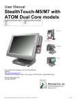
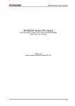
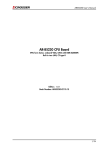
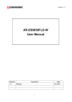
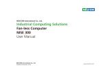
Revision: 1.0
AR-B5403 Board
Socket P Intel® Core™2 Duo EPIC SBC
with Intel® 945GM Express Chipset, Built in two LAN, CF type-II
User Manual
Manual Rev.: 1.0
Book Number: AR-B5403-2010.09.03
1
Revision: 1.0
Revision
Version
1.0
Date
Author
2010/09/03 Cody
Description
Initial release
2
Revision: 1.0
Copyright 2010
All Rights Reserved.
Manual’s first edition: Sept, 02, 2010
For the purpose of improving reliability, design and function, the information in this document is
subject to change without prior notice and does not represent a commitment on the part of the
manufacturer.
In no event will the manufacturer be liable for direct, indirect, special, incidental, or
consequential damages arising out of the use or inability to use the product or documentation, even
if advised of the possibility of such damages.
This document contains proprietary information protected by copyright. All rights are reserved.
No part of this Manual may be reproduced by any mechanical, electronic, or other means in any
form without prior written permission of the manufacturer.
Trademarks
AR-B5403 is a registered trademarks of Acrosser; IBM PC is a registered trademark of the
International Business Machines Corporation; Pentium is a registered trademark of Intel
Technologies Inc; Award is a registered trademark of Award Software International Inc; other
product names mentioned herein are used for identification purposes only and may be trademarks
and/or registered trademarks of their respective companies.
3
Revision: 1.0
Table of Contents
1 Introduction .......................................................................................... 5
1.1 Features......................................................................................................... 5
1.2 Package Contents ......................................................................................... 7
1.3 Block Diagram ............................................................................................... 8
2 H/W Information.................................................................................... 9
2.1 Locations ....................................................................................................... 9
2.2 Connector and Jumper Setting Table ........................................................ 12
3 BIOS Setting ....................................................................................... 20
3.1 Main Setup ................................................................................................... 21
3.2 Advanced Chipset Setup ............................................................................ 22
3.3 PnP/PCI Setup ............................................................................................. 23
3.4 Peripherals Setup........................................................................................ 24
3.5 PC Health Setup .......................................................................................... 25
3.6 Boot Setup ................................................................................................... 26
3.7 Exit Setup .................................................................................................... 27
4
Revision: 1.0
1
INTRODUCTION
Welcome to the AR-B5403 Computer. The AR-B5403 is an Intel Core 2 Duo EPIC single board
computer provides variety of display outputs. In addition to VGA, DVI and LVDS display outputs,
AR-B5403 supports S-Video, BNC, and component TV outputs.
1.1 Features
Processor: Core 2 Duo, Core Duo and Celeron M
Chipsets: 945GM + ICH7M
Memory: DDR2 533/667MHz SO-DIMM, Maximum 2GB
Display: VGA, DVI, LVDS, TV Out
Storage: 1x CF, 2x SATA II,
Audio: Line-out, Mic-in
Communication: 2x Gbps Ethernet, 7x USB 2.0, 3x RS-232, 1x RS-232/422/485
General: Watchdog timer, 8-bit GPIO, and PCI-104 expansion slot.
Specifications
System
CPU
Chipset
FSB
Memory
Video
Graphic
Controller
Video Memory
Video Interface
Storage
SATA
CF
Disk Bay
I/O
Ethernet
Serial Port
Support Intel Core 2 Duo/Core Duo/Core Solo/Celeron M
CPU T7400 / T5500 / T2500 / CM440
CPU: L7400
Intel 945GME+ICH7M
533/667MHz
One SO-DIMM socket support 667/533 MHz DDR2 SDRAM up to 2GB
1G Bytes 667MHz DDRII pre-installed
Intel 945GME integrated GMA 950 graphic controller
DVMT 3.0, Maximum 256MB shared
1 x VGA port (DB15)
2 x SATA II port,
1 x External Compact Flash Type I/II socket
1 x Anti-shock 2.5" HDD bracket swappable without open case
2 x Gbps RJ45 with LED, Broadcom BCM5787
4 x RS-232
5
Revision: 1.0
(2 x DB9, 2 x pin header, COM3 for reserve for PIC on power circuit,
COM4 for GPS
USB
7 x USB2.0
(4 x external port, 3 x pin header)
GPIO
4-bit GPIO (2 In, 2 Out) with 5 pin terminal block, 2-in/GND/2-out
Audio
IC: Realtek ALC655
Interface : MIC-In, SPK-Out
Remote control 1 x Remote control
Fuse
7.5A
Antenna Hole 1 x SMA for GPS, 1 x SMA for 3.5G, 1 x SMA for WiFi+Bluetooth
miniPCIe
1 x miniPCIe option for MC8790
SIM
SIM slot x1, SIM card changeable without opening case, latch to protect
SIM uncertainly touch
Expansion
PCI-104
Keep design, remove PCI-104 slot
Others
GPS(option)
Globalsat ER-332
3.5G(option)
Sierra MC 8790/8790V, through miniPCIe slot on AR-B5403
WiFi(option)
(1)2 in 1 module (WLBT-Combo-E), (2)
Bluetooth
2 in 1 module (WLBT-Combo-E)
Software
OS support
Windows XP/ XP embedded, Linux FC 6 /7
Power
Power onboard design(AR-B5403)
Wide range input DC 9V~32V
Fuse Design
Smart ATX power function:
a. Power on/off retry
b. Adjustable delay time for system OFF by Switch on power module
(Mode2~Mode7)
c. System on/off by Vehicle ignition or Remote switch button
d. Low Power input monitoring, Auto shutdown
S/W configurable by COM3
Remote switch(audio jack)
System status LED(blue)
Embedded power local switch
AR-PW0932V default is Mode 2
Mechanical & Environment
Thermal Design Heat pipe solution
Chassis
Metal steel
Material
Bracket
Bracket with anti-thief function (Locker option)
Dimension
T.B.D.
Vibration
IEC 60068-2-64 5~500Hz, 3GRMS for SSD/CF, 1GRMS for 2.5”HDD,
operating
Shock
IEC 60068-2-27 50G-500m/s -11ms, operating
Operating
-15~50℃ with Industrial Grade CF or SSD
Temp.
Storage Temp. -40~80℃
Certification
CE/FCC class B
6
Revision: 1.0
1.2 Package Contents
Check if the following items are included in the package.
Quick Manual
AR-B5403 board
1 x Software Utility CD
7
Revision: 1.0
1.3 Block Diagram
8
Revision: 1.0
2
H/W INFORMATION
This chapter describes the installation of AR-B5403. At first, it shows the Function diagram and
the layout of AR-B5403. It then describes the unpacking information which you should read
carefully, as well as the jumper/switch settings for the AR-B5403 configuration.
2.1 Locations
2.1.1 Top Side
CPU
CPU Socket
GMCH
Graphic Memory Control Hub Intel 945GME
ICH7M
Graphic Memory Control Hub Intel GM45
USB Port and LAN
2 USB and 1 RJ-45 for LAN
USB Port and LAN
2 USB and 1 RJ-45 for LAN
Power LED and HDD LED
Power LED and HDD LED
Local Switch
12V Power Switch
Status LED
Machine Status LED
GPIO Port
Power Connector
12V Power Connector
Remote Switch and Audio
Remote Power Control and Audio I/O
COM Port
RS232 Serial Ports (COM1 & COM2)
VGA
VGA Port
BIOS
User Defined GPIO Port
LAN Chip
Broadcom BCM5787 Gigabit Ethernet
BIOS IC
SATA1
SATA Data Connector
Mini-PCIE for 3G module
3G Module slot with USB interface
SATA2
SATA Data Connector
9
Revision: 1.0
2.1.2 Bottom Side
SO-DIMM Socket
SO-DIMM Socket for DDR2
CF Slot
CF Slot for CF Card support IDE Mode
SIMM Card Socket
SIMM Card Socket for 3G Module
10
Revision: 1.0
2.1.3 List of Connector and Jumper Setting
PWR1
12V, 5V Output
COM4
Pin Header for COM4 Port
J6
CF Card Master setting
J12
Connector for Programming PIC
DVI3
DVI Output Port
BAT1
Battery Input
JP4
Define KEY_SW, ENG_STS input type
FAN2
CPU FAN Connector
CN2
3.5G Carrier Board Status LED
CN10
Reserve Pin
TVCON1
TV Output Port
LCDPW1
Backlight Power and Control signal
J11
Front Panel Connector
J1
LVDS Panel Power Select
LCD1
LCD Signal Output
Fuse1
Fuse Connector
CN8
+5V, +12V for External Module
CON7
SATA Device Power
SW1
DIP Switch for Power Mode Select
J10
Jumper Select for GPIO Configuration
JP1
COM2 Transfer Protocal setting
FAN1
System Fan Connector
USB2
Pin Header for USB Ports
CON2
SATA Device Power
IR1
IR Port
USB3
Pin Header for USB Ports
J5
COM2 RS-422,RS-485 Output
CN9
+5V, +12V for External Module
J9
Power SW, Reset, Buzzer Connector
JBAT1
Pin Header for CMOS Clear
11
Revision: 1.0
2.2 Connector and Jumper Setting Table
1. PWR1 (12V,5V Output)
2. J12 (Connector for PIC
Programming)
PIN
DEFINE
PIN
DEFINE
1
+12V
2
GND
3
4
GND
+5V
1
2
3
4
5
+5VSB
ISPDATA
ISPCLK
ISPVPP
GND
4. CN10 (GPO reserve)
3. JP4 (Define Key_SW,
ENG_STS Input Type)
Status
5. J11(Front Panel Connector)
(Note1)
SIGNAL
PIN
Signal
1
GPO
2
GND
1
3
PWRBTN_IN
LOC_SW
2
4
GND
GND
5
KEY_SW
6
GND
7
ENG_STS
8
GND
9
STS_LED
10
GND
PIN
7. SW1 (DIP switch for
power mode select)(Note2)
1
2
3
4
0
ON
ON
ON
ON
1
ON
ON
ON
OFF
2
ON
ON
OFF
ON
3
ON
ON
OFF OFF
4
ON
OFF
ON
5
6
ON
ON
OFF ON OFF
OFF OFF ON
7
ON
OFF OFF OFF
ON
PIN
SIGNAL
1
GND
2
12V
3 FAN Speed Detect
12
Active High
Short
Active Low
6. FUSE1 (Connect to Fuse)
PIN Signal
8. FAN1 (System FAN)
Mode
Open
PIN
Signal
1,2
Fuse Out
3,4
Fuse In
9. IR1 (IR Pin Header)
PIN
DEFINE
1
+5V
2
3
4
5
NC
IR_RX
GND
IR_TX
Revision: 1.0
10. J5 (COM2 RS-422,RS-485
Output)
PIN
SIGNAL
1
TX+
11. J9 (Power Button & Reset &
Buzzer)
12. COM4 (Pin Header for
COM4)
※PWRBTN for ATX mode only
PIN SIGNAL
2
TX-
3
RX+
4
RX-
PIN SIGNAL
13. DVI3 (DVI Port)
14.
PIN
SIGNAL
PIN
1
GND
2
TD0
3
TD0-
4
GND
SIGNAL
1
DCD
2
DSR
1
5V
2
PCBEEP
3
RX
4
RTS
3
GND
4
RESET
5
TX
6
CTS
5
GND
6
PWRBTN
7
DTR
8
RI
9
GND
10
NC
FAN2 (CPU Fan connector) 15. TVCON1 (TV Output Port)
SIGNAL
5
TD1
6
TD1-
7
GND
8
TD2
9
TD2-
10
GND
11
TCK
12
TCK-
13
HPD
14
DDCCLK
15
VCC
16
DDCDATA
17
RED
18
GND
19
GREEN
20
GND
21
BLUE
22
GND
23
VSYNC
24
25
HSYNC
26
CRT
DDCCLK
CRT
DDCDATA
PIN
Signal
PIN
SIGNAL
1
1
GND
3
S-Video
Luminance
GND
2
12V
5
CVBS
FAN Speed Detect
7
3
16 J1 (LCD Panel Power Select)
SETTING
17 CN8 (Power Connect for
+12V and +5V)
PIN
DEFINE
1
+12V
GND
GND
+5V
1-2 close
+5V
2
2-3 close
+3.3V
3
4
13
PIN
Signal
2
Reserve
4
Reserve
6
NC
GND
8 Reserve
S-Video
9
10
GND
Chrominance
11
GND
12
NC
13
STATUS
PIN SIGNAL
PIN
NC
14
NC
18 J10 (Jumper Select for
GPIO configuration)
PIN
DEFINE
1-2
3-4
5-6
7-8
9-10
11-12
NC(DEFAULT)
NO
GND(DEFAULT)
+5V
+12V
+EXT
Revision: 1.0
19. USB2 (USB Output Port)
PIN SIGNAL
PIN SIGNAL
20. USB3 (USB Output Port)
PIN SIGNAL
PIN SIGNAL
21. CN9 (Power Connect for
+12V and +5V )
PIN
DEFINE
1
+5V
2
+5V
1
+5V
2
NC
1
+12V
3
DATA3-
4
DATA2-
3
DATA7-
4
NC
2
GND
5
DATA3+
6
DATA2+
5
DATA7+
6
NC
7
GND
8
GND
7
GND
8
NC
3
4
GND
+5V
9
GND
10
GND
9
GND
10
NC
22. JBAT1 (Pin Header for
CMOS Clear)
STATUS
23. J6 (CF Card status)
24. BAT1 (Battery Connector)
SETTING
STATUS
SETTING
1-2
Normal
SHORT
Master
2-3
Clear CMOS
OPEN
Slave
14
PIN
SIGNAL
1
VBAT
2
GND
Revision: 1.0
25. CN2 (3.5G Module
Status)
PIN
SIGNAL
1
+3.3V
2
Status Signal
28. CON7
(+12V,+5V,+3.3V for SATA
HDD Power)
PIN
DEFINE
1
+12V
2
3
4
GND
+3.3V
+5V
26. LCDPW1 (Backlight Output) 27. LCD1 (LCD Signal Output)
PIN
DEFINE
1
+12V
2
+12V
3
4
5
6
GND
Backlight Enable
GND
Backlight Control
29. JP1 (COM2 Type Setting)
STATUS
SETTING
1-2
RS-232
3-4
RS-422
5-6
RS-485
15
PIN
SIGNAL
PIN
SIGNAL
1
3
5
7
9
11
13
15
17
19
21
23
25
27
29
LCDVCC
B CLKGND
B DATA2+
B DATA1NC
B DATA0+
GND
A CLKA DATA2+
I2C CLK
A DATA1A DATA0+
NC
LCDVCC
2
4
6
8
10
12
14
16
18
20
22
24
26
28
30
GND
B CLK+
B DATA2GND
B DATA1+
NC
BDATA0A CLK+
GND
A DATA2A DATA1+
I2C DATA
A DATA0NC
LCDVCC
30. CON2 (+12V,+5V,+3.3V for
SATA HDD Power)
PIN
DEFINE
1
+12V
2
GND
3
4
+3.3V
+5V
Revision: 1.0
Note1,2 Power smart function
Definition
1. Soft off cycle:
A period when received power off signal to generate a off signal (A 500mS pulse, HighLow –High or Low-High-Low depends on SIO configuration, to mother board’s Power
Button Pin)
2. Hard Off cycle:
A period when system off (S5) to stand by removed (G3). In another word, the A period of
5VSB on to off (when system already off)
Notes: S5 and G3 is follow by ACPI
Mode description
The main power-in is controlled by the switch on chassis.
Maximum 16 Modes adjusted by 4 switches. (Mode 8 to mode 15 are reserved for future use).
Mode 0: ATX mode.
A. 5V Standby is always on.
B. Input voltage is not monitored.
C. Power on/off is controlled by remote switch
D. Local Switch priority is higher than remote switch. This is controlled by hardware.
Mode 1: AT mode
A. Power output immediately after input is present.
B. Power can only be turned off by turning off local switch. The remote switch will be ignored by
Power smart function. In this mode the BIOS shall be set to AT mode.
Smart Mode (Mode 2 to Mode 7)
Mode 2: See Figure 1
A. Power on is controlled by ignition (remote switch does not make any action to power
on).
B. Power on retry: If the motherboard cannot be turned on normally (/PSON does not go to
low), the Power smart function will turn off 5VSB, and then turn on 5VSB and retry. Send
“on” pulse to motherboard again. The power board will re-try this procedure until
successfully turn on motherboard.
C.
Power smart function sends “ON” pulse to motherboard when ignition is on for more than 2
seconds.
D.
Power smart function will ignore the status change of ignition after ON pulse is send to
motherboard for 3 minutes. After this period, the Power smart function will start to check its
status. This can avoid an improper “OFF” process before the OS is complete booted.
E.
Power off is controlled by remote switch or ignition. Remote switch has higher priority
than ignition. (Remote switch is optional).
F.
Power smart function sends “off” pulse to motherboard 5 seconds after ignition is turned off
or remote switch is pressed. (Soft delay)
G. Power smart function will ignore the status change of ignition and remote switch during the
“OFF” pulse is sent out and the /PSON return to high. This will avoid an improper ON
process before the motherboard is completely shot off.
16
Revision: 1.0
H. The digital output (optional) will go from high to low at the moment that “OFF” pulse is sent
to motherboard. The low state will be kept until /PSON back to high. If the /PSON does not
back to high within 3 minutes, the Power smart function will enter a retry cycle (described in
next section).
I. Power off retry: If the motherboard cannot be shouted down normally (/PSON does not go to
high) within 3 minutes after “OFF” pulse is sent, the Power smart function will send off pulse
to motherboard again. If the motherboard still cannot be shouted down normally, the power
output will be turned off directly. (Figure 3)
J. Hard off delay: 1 minutes, During this period system can be turned on again if the off
procedure already finished and power button is pushed again(or ignition on again)
Mode 3:
A. Same as mode 2 except for soft/hard off delay time
B. Soft off delay: 1 minute
C.Hard off delay: 5 minutes
Mode 4:
A. Same as mode 2 except for soft/hard off delay time
B. Soft off delay: 30 minute
C.Hard off delay: 2 Hours
Mode 5: See Figure 2
Same as mode 2 except that the power on is controlled by remote switch.
A. Power on is controlled by remote switch (ignition must be turned on 2 seconds before
remote switch is pressed).
B. AR-PW0932V sends off pulse to motherboard 5 seconds after ignition is turned off or remote
switch is pressed. (Soft delay)
C.Hard off delay: 1 minutes
Mode 6:
A. Same as mode 5 except for soft/hard off and delay
B. Soft off delay: 1 minute
C.Hard off delay: 5 minutes
Mode 7:
A. Same as mode 5 except for soft/hard off and delay
B. Soft off delay: 30 minute
C.Hard off delay: 2 Hours
Mode15(Software control mode):
A. Setting by AP
B. Software mode default as Hardware mode 2
C. Soft off delay time can be set
D. Hard off delay time can be set
E. In-Vehicle system power on by ignition or Remote button can be set
17
Revision: 1.0
F. Show Ignition status / Voltage(for AP only)
Engine status
G. Create a button "Set default"
Car Battery
System on by
Ignition
Remote Switch
Soft off delay time
seconds
Hard off delay time
seconds
Set Default
Plan AP screen
OK
Cancel
Table 1. Control Mode
Mode
0 (ATX)
1(AT)
2
3
4
5
6
7
15 (Software
control)
Soft OFF
Delay
No
No
5 seconds
1 minute
30 minutes
5 seconds
1 minute
30 minutes
By user setting
Hard OFF
delay
No
No
1 minute
5 minutes
2 hours
1 minute
5 minutes
2 hours
By user setting
Power ON
Control
Power OFF Control
Remote Switch
Local Switch
Ignition
Ignition
Ignition
Remote Switch
Remote Switch
Remote Switch
By user setting
Remote Switch
Local Switch
Ignition / Remote Switch
Ignition / Remote Switch
Ignition / Remote Switch
Ignition / Remote Switch
Ignition / Remote Switch
Ignition / Remote Switch
Ignition / Remote Switch
Another function of Smart Mode
1.
If ignition turns back “ON” during “Off” Delay, Power smart function will stay in operation. “Off”
signal will not be send to motherboard. The “Off” Delay will re-start after next ignition off.
2.
Power input monitoring(before system boot on, during runtime, during soft off delay): The
Power smart function will constantly monitor the input voltage. If the input voltage is below X
Voltage (the standard might have 5% tolerance), the AR-PW0932V will not start the power
on procedure. When Power smart function has ran in operation and the battery drops below Y
Voltage (with 5% tolerance) more than 10 seconds the Power smart function will shut down
the motherboard following the standard shut down procedure. If the input voltage recovers in
18
Revision: 1.0
10 seconds over Y Voltage (with 5% tolerance) again, the Power smart function will continue
to run. (Figure 4)if this happens, ignition shall be off and on again (Mode 2, 3, 4) or press the
remote switch(Mode 5,6,7) if you want to turn on system again.
X value
Y value
For 12V car battery
11.2
10.8
19
For 24V car battery
23
22.5
Revision: 1.0
3
BIOS SETTING
This chapter describes the BIOS menu displays and explains how to perform common tasks
needed to get the system up and running. It also gives detailed explanation of the elements found
in each of the BIOS menus. The following topics are covered:
Main Setup
Advanced Chipset Setup
PnP/PCI Setup
Peripherals Setup
PC Health Setup
Boot Setup
Exit Setup
Once you enter the Award BIOS™ CMOS Setup Utility, the Main Menu will appear on the
screen. Use the arrow keys to highlight the item and then use the <Pg Up> <Pg Dn> keys to select
the value you want in each item.
20
Revision: 1.0
3.1 Main Setup
The <Main Setup> choice allows you to record some basic hardware configuration in your
computer system and set the system clock and error handling. If the motherboard is already
installed in a working system, you will not need to select this option. You will need to run this Setup
option, however, if you change your system hardware configuration, the onboard battery fails, or
the configuration stored in the COMS memory was lost or damaged.
Note: Listed at the bottom of the menu are the control keys. If you need any help with the item
fields, you can press the <F1> key, and it will display the relevant information.
Option
Choice
Description
Date Setup
N/A
Set the system date. Note that the ‘Day’ automatically
changes when you set the date
Time Setup
N/A
Set the system time
IDE Channel 0
Master/Slave
N/A
The onboard PCI IDE connectors provide 1 channel for
connecting up to 2 IDE hard disks or other devices. The first
is the “Master” and the second is “Slave”, BIOS will
auto-detect the IDE type.
Halt On
All Errors,
No Errors,
All but keyboard.
Select the situation in which you want the BIOS to stop the
POST process and notify you.
21
Revision: 1.0
3.2 Advanced Chipset Setup
This section allows you to configure and improve your system and follows you to set up some
system features according to your preference.
Option
Choice
Quick Power On Self
Test
Enabled
Disabled
This category speeds up Power On Self Test (POST) after you
have powered up the computer. If it is set to Enable, BIOS will
shorten or skip some check items during POST.
Full Screen Logo
Show
Enabled
Disabled
Select Edabled to show the OEM full screen logo if you have
add-in BIOS.
USB Keyboard
Support
Enabled
Disabled
Select Enabled if you system contains a Universal Serial Bus
(USB)controller and you have a USB keyboard.
On-Chip Frame
Buffer Size
1Mb
8Mb
Boot Display
Panel Type
DVWT mode
DVWT/FIXED
Memory Size
CRT
LCD
CRT+LCD
TV
800x600,
1024x768,
1280x1024
FIXED
DVMT
Both
64Mb
128Mb
Description
This Item is for setting the Frame Buffer (Share system memory
as display memory).
This Item is to set display device
TV function only support on AR-B5230SD
This Item cab Set the LVDS panel resolution that you want
This item sets the mode for dynamic video memory thechology
(DVMT).
This item sets the DVMT size
22
Revision: 1.0
3.3 PnP/PCI Setup
The option configures the PCI bus system. All PCI bus system on the system use INT#, thus
all installed PCI cards must be set to this value.
Option
Choice
Description
Enabled
Disabled
Normally, you leave this field Disabled. Select Enabled to
reset Extended System Configuration Data (ESCD) when you
exit Setup. If you have installed a new add-on and the system
reconfiguration has caused such a serious conflict, then the
operating system cannot boot.
Resources
Controlled By
Auto(ESCD)
Manual
The Award Plug and Play BIOS has the capacity to
automatically configure all of the boot and Plug and Play
compatible devices. However, this capability means absolutely
nothing unless you are using a Plug and Play operating
system such as Windows 95. If you set this field to “manual,”
then you may choose specific resources by going into each of
the submenus.
IRQ Resources
N/A
Reset Configuration
Data
When resources are controlled manually, assign a type to
each system interrupt, depending on the type of the device
that uses the interrupt
23
Revision: 1.0
3.4 Peripherals Setup
This option controls the configuration of the board’s chipset. Control keys for this screen are
the same as for the previous screen.
Option
Onboard Serial Port 1
Onboard Serial Port 2
Onboard Serial Port 3
Onboard Serial Port 4
Choice
Serial Port 1: 3F8 / IRQ4
Serial Port 2: 2F8 / IRQ3
Serial Port 3: 3E8 / IRQ11
Serial Port 4: 2E8 / IRQ10
Description
USB Controller
Enabled
Disabled
Select Enabled if your system contains
a Universal Serial Bue (USB)controller
and you have USB peripherals
USB 2.0 Controller
Enabled
Disabled
Select Enabled if your system contains
a Universal Serial Bue (USB) 2.0
controller and you have USB
peripherals
AC97 Auido Function
Enabled
Disabled
Audio/Modem
On chip IDE DEVICE
Enabled
Disabled
Select an address and the corresponding
interrupt for each serial port.
This item allows you to decide to
enable/disable AC97 Audio
The integrated peripheral controller
contains an IDE interface with support for
two IDE channels. Select Enabled to
activate each channel separately.
24
Revision: 1.0
3.5 PC Health Setup
This section shows the parameters in determining the PC Health Status. These parameters
include temperatures, fan speeds, and voltages.
25
Revision: 1.0
3.6 Boot Setup
This section is used to exit the BIOS main menu. After making your changes, you can either
save them or exit the BIOS menu and without saving the new values.
Option
First / Second / Third
Boot Device/Other Boot
Device
Choice
Hard Disk
CDROM
USB-FDD
USB-CDROM
LAN
Disabled
LAN Boot Select
Enabled
Disabled
Hard Disk Boot Priority
N/A
Description
The BIOS attempts to load the operating
system from the devices in the sequence
selected in these items.
These fields allow the system to search
for an OS from LAN
These fields set the Boot Priority for each
Hard Disk
26
Revision: 1.0
3.7 Exit Setup
This section is used to configure exit mode.
Option
Choice
Description
Pressing <Enter> on this item
for confirmation:
Save & Exit Setup
Save to CMOS and EXIT
(Y/N)? Y
Load Optimized Defaults
When you press <Enter> on
this item you get a
confirmation dialog box with a
message like this:
Press “Y” to store the selections made in
the menus in CMOS – a special section of
memory that stays on after you turn your
system off. The next time you boot your
computer, the BIOS configures your system
according to the Setup selections stored in
CMOS. After saving the values the system
is restarted again
Press ‘Y’ to load the default values that are
factory-set for optimal-performance system
operations.
Load Optimized Defaults
(Y/N)? N
Exit Without Saving
Pressing <Enter> on this item
for confirmation:
This allows you to exit Setup without storing
any changes in CMOS. The previous
selections remain in effect. This shall exit
Quit without saving (Y/N)? Y the Setup utility and restart your computer.
27
Revision: 1.0
When a password has been enabled, you
will be prompted to enter your password
every time you try to enter Setup. This
prevents unauthorized persons from
changing any part of your system
configuration.
Set Password
Pressing <Enter> on this item
for confirmation:
ENTER PASSWORD:
Type the password, up to eight characters
in length, and press <Enter>. The password
typed now will clear any previous password
from the CMOS memory. You will be asked
to confirm the password. Type the
password again and press <Enter>. You
may also press <Esc> to abort the selection
and not enter a password.
To disable a password, just press <Enter>
when you are prompted to enter the
password. A message will confirm that the
password will be disabled. Once the
password is disabled, the system will boot
and you can enter Setup freely.
28