1
Wireless Lighting Control
ZDS-UD10
Dimming Switch Module
USER MANUAL
Z-Wave® Certified
Wireless Lighting Control
Rev 04
~1~
2011/02/09
Introduction:
Thank you for choosing AMC ZDS-UD10 Z-Wave® control product. Our Z-Wave® enabled product
allows user to remotely control lighting, home appliance, and make home control easy at low installation /
maintenance cost. You may begin with a few Z-Wave® enabled devices or build up a complete home
automation system with our products.
The ZDS-UD10 Dimming Switch Module is a Z-Wave® enabled device and fully compatible with any
Z-Wave® enabled network. It allows remote Dimming or On/Off control of specified lamps; Each module
is designed to act as a repeater, which will re-transmit the RF signal to ensure that the signal is received
by its intended destination by routing the signal around obstacle and radio dead spots.
Glossary
Devices, lights and nodes are all terms to describe an
individual Z-Wave
Device/Light/Node
device. These are all interchangeable when setting up your
Z-Wave network.
Inclusion
Add a Z-Wave device to the network.
Exclusion
Delete a Z-Wave device from the network.
Associations are used to set up one node to automatically
contact another
node when the first is triggered. For example you can set up a
Association
door sensor (primary node) to turn on the light (secondary
node) when the door has been opened.
~2~
Key Features:
- Selective slide switch for DIMMER/SWITCH mode
- High output power in SWITCH mode
- High output power in DIMMER mode
- One Z-wave controlled AC outlet for standard incandescent lighting and AC LED lamp.
- One Always-ON pass-through AC outlet
- Remote ON/OFF and Brightness control via the Z-Wave controller
- Manual ON/OFF and Brightness control with the front panel push button
- Fine appearance designed
- Space efficient design
- Does not block the lower outlet when plugged into the upper outlet of a duplex wall receptacle.
(This assumes that the duplex receptacle is mounted with the ground pin down.)
- Plugs and cords for connected devices route to the side allowing close placement of furniture
- Grounded 3-wire power connection for safety
- Over temperature protection
Configurations:
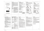
A … ON/OFF/DIMMER/PROG Push button
B … Always on outlet
C … Z-Wave controlled outlet
D … AC plug
E … Selective switch (On/Off or Dimming Model)
!Warning
The incandescent (or LED) light plugged into the Z-Wave® controlled outlet on this module must not
exceed 330 watts. DO NOT connect fluorescent light. Plugging a non-resistive load such as fluorescent
light or a device with a motor into the Z-Wave® controlled outlet may result in damage to the ZDS-UD10
Dimming Switch Module and will void the warranty.
~3~
Basic Operation
The connected light can be turned ON in two ways:
1.
Manual control with the push button on the ZDS-UD10.
2.
Z-Wave remote controller.
Manual ON/OFF/DIM function
1.
Switch to DIMMER mode
DIMMER MODE
2.
Plug the lamp into the Dimming Switch Module outlet which is labeled with “Z-Wave”.
Ensure that the loading does not exceed 330 Watts.
~4~
3. Plug the Dimming Switch module into a wall AC outlet.
4. Turn the light On/Off by pressing the button.
(This is a toggle switch - Press the button to turn the light On if it is in Off stage and vice versa)
5. Adjust the brightness level by pressing and holding the button. Release the button when the desired
level is attained.
(This is also a toggle function – Press and hold the button to dim-up the light and press and hold the
button again to dim-down the light)
~5~
6. In the SWITCH mode, turn the light On/Off by pressing the button.
(This is a toggle switch - Press the button to turn the light On if it is in Off stage and vice versa)
SWITCH MODE
~6~
Z-Wave Remote Control
Include or exclude the Dimming Switch module from the existing Z-Wave home control network with your
primary controller.
z
Refer to your primary controller instructions to process the inclusion / exclusion setup
procedure.
z
When prompted by your primary controller, tap the button.
z
The primary controller should indicate that the action was successful. If the controller indicates
the action was unsuccessful, please repeat the procedure.
z
Once the Dimming Switch module is part of the network, the same basic procedure is used to
add the Dimming Switch module to groups or scenes. Refer to the primary controller’s
instructions for details.
All On/All Off functions
Depending upon your primary controller, the Dimming Switch Module can be set to respond to ALL ON
and ALL OFF commands up to four different ways. Some controllers may not be able to change the
response from its default setting. Please refer to your controller’s instructions for information on whether
or not it supports the configuration function and if so, how to change this settings.
The four possible responses are:
z
It will respond to ALL ON and the ALL OFF commands (default).
z
It will not respond to ALL ON and ALL OFF commands.
z
It will respond to the ALL OFF command but will not respond to the ALL ON command.
z
It will respond to the ALL ON command but will not respond to the ALL OFF command.
Restoring Factory Defaults
All Configuration Parameters can be restored to their factory default settings by using your primary
controller to reset the device. (delete from the network)
~7~
There is no user serviceable parts in the Dimming switch module.
To avoid the risk of electric shock, the input prong comes with a round grounding plug. The switch module
can only be plugged in to the power inlet with the grounding plug. Please contact a qualified electrician to
replace the power inlet if it has no grounding inlet. Do not change the plug of Dimming switch model in
any way.
RISK OF FIRE
RISK OF ELECTRICAL SHOCK
RISK OF BURNS
DID NOT QUALIFY FOR INSTRUMENT OF MEDICAL AND LIFE SUPPORT EQUIPMENT
Z-Wave Dimming switch module never got qualified certificate to supply power for medical instrument or
any life support equipment.
This Dimming switch module is complied with the Z-Wave standard of open site, line of sight transmission
distances of up to 25m. Actual RF performance of Dimming switch module in a home was affected by the
number of barrier/construction between the remote controller and the destination unit, in meanwhile,
relies on the number of Z-Wave enabled devices installed in the control network.
WARRANTY
Dimming switch module warrants the product to be free from manufacturing defects for a period of one
year from the original date of consumer purchase. This warranty is limited to the repair or replacement of
the product only and does not extend to consequential or incidental damage to other products that may
be used with this product.
This warranty is instead of all other warranties, expressed or implied. Some states do not allow limitations
on how long an implied warranty lasts or permit the exclusion or limitation of incidental or consequential
damage, so the above limitations may not apply to you.
This warranty gives you specific rights, and you may also have other rights which vary from state to state.
Please contact Customer Service at 852-2558-8383 between 9:00AM - 5:00PM GMT Beijing or via our
website (www.amchk.com) if the unit should prove defective within the warranty period.
Airline Mechanical Co., Ltd
20F., Kam Man Fung Factory Building,
6 Hong Man Street, Chai Wan, Hong Kong
~8~
TECHNICAL SPECIFICATIONS
Rating input:
120Vac
Input frequency:
60Hz
RF frequency:
908.42MHz (ZDS-UD10)
Max. range:
up to 25m
Double outlets:
Z-Wave controllable
“Always On” pass through
Selectable switch:
DIMMER(Dimming/ON/OFF) or SWITCH(ON/OFF) mode
Max. output power of Z-Wave controlled:
DIMMER:
Max Incandescent load 330W 2.5A
SWITCH:
a. Max Incandescent Load 330W 2.5A
b. Max Resistive Load 600W 5A
Max. power of “Always On” pass through
Resistive load 1200W
outlet:
Max. power in total for both Z-Wave Outlet
Resistive load 1500W
and Always on Pass through outlet:
Connect ability:
DIMMER:
Can only be connected to incandescent lamp , AC
LED Lamp, Resistive
SWITCH:
Can be connected to incandescent lamp, AC LED
lamp, Resistive
Over Temperature protection:
Detected internal temperature, and cut off output once
OTP triggered.
(Remark: Under Over Temperature situation, it will fail to
start up).
EMC:
Meet FCC15 Class B
Safety:
Meet UL244A standard
Dimension (L x W x H):
126X68X40mm
Weight:
180g
Storage:
-10~60℃
Operation Temperature:
0~40℃
Relative Humidity:
5~95%
Environment:
Indoor use only
Specifications subject to change without notice due to continuing product improvement
~9~