1
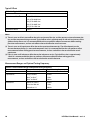
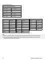
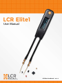
LCR Elite1
User Manual
LCR Elite1 User Manual - ver 1.0
Notices
The information contained in this document is provided “as is”, and is subject to change, without notice, in
future editions.
This document contains proprietary information that is protected by copyright. All rights are reserved. No
part of this document may be photocopied, reproduced, or translated to another language without the prior
agreement and written consent from LCR Research Ltd.
© LCR Research Ltd. 2015
Warranty
LCR Research warrants this product to be free from defects in materials and workmanship for a period of
one (1) year from the shipment date. LCR Research warrants the following items for ninety (90) days from
the date of shipment: rechargeable batteries, gold plated tips and documentation. During the warranty
period, LCR Research will, at its option, either repair or replace products that prove to be defective. For
warranty service or repair, this product must be returned to a service facility designated by LCR Research.
The buyer shall prepay shipping charges to LCR Research, and LCR Research shall pay shipping charges to
return the product to the buyer. However, the Buyer shall pay all shipping charges, duties, and taxes for
products returned to LCR Research from another country. Repaired or replaced products are warranted for
the balance of the original warranty period.
Limitation of Warranty
This warranty does not cover normal wear and tear and scratches on surface or screen. This warranty does
not cover physical damage to the screen, switch and/or button; electrical damage of the product due to high
voltage or improper battery type. This warranty does not cover to any product from which the serial number
has been removed or that has been damaged or rendered defective resulting from improper or inadequate
maintenance by the Buyer, software, interfacing or parts not supplied by LCR Research, unauthorized
modification or misuse, operation outside the usage parameters stated in the user documentation, or
improper site preparation or maintenance.
LCR Research specifically disclaims no other warranty is expressed or implied, including the implied
warranties of merchantability or fitness for a particular purpose. LCR Research shall not be liable for errors
or for incidental or consequential damages in connection with the furnishing, use, or performance of this
document or of any information contained herein.
Exclusive Remedies
The remedies provided herein are the Buyer’s sole and exclusive remedies. LCR Research shall not be liable
for any direct, indirect, special, incidental, or consequential damages, whether based on contract, tort, or
any other legal theory. Such excluded damages shall include, but are not limited to: costs of removal and
installation, losses sustained as the result of injury to any person, or damage to property.
LCR Elite1 User Manual - ver 1.0
Safety Notices
CAUTION
Caution must be observed to avoid minor injury to yourself or damage to the product or other property.
WARNING
Warnings must be followed carefully to avoid personal injury, death or damage to the product or other property.
Safety Considerations
Read the information below before using this metre. This metre is intended for use by qualified personnel who
recognize shock hazards and are familiar with the safety precautions required to avoid possible injury. The
following general safety precautions must be observed during all phases of operation, service, and repair of this
metre. Failure to comply with these precautions or with specific warnings elsewhere in this manual violates safety
standards for design, manufacture, and intended use of the metre. LCR Research assumes no liability for the
customer’s failure to comply with these requirements.
CAUTION
•
•
•
•
Disconnect circuit power and discharge all high-voltage capacitors before testing.
When measuring in-circuit components, first de-energize the circuits before connecting them to the test tips.
The battery must be charged by a computer USB port or a USB power adapter that provides output voltage
DC 5V ± 5%.
This metre is for indoor use at altitudes of up to 2000 metres.
WARNING
•
•
•
•
•
•
•
•
•
•
Use this metre only as specified in this manual; otherwise, the protection provided by the metre may be impaired.
Do not use the metre if it is damaged. Before you use the metre, inspect the case. Look for cracks or missing plastic.
Inspect the test tip sleeves for damaged insulation or exposed metal. Check the test tips for continuity. Replace
damaged test tip sleeves before you use the metre.
Do not touch exposed metal in measurement. Keep your fingers on insulated test tip sleeves.
Do not use the metre if it operates abnormally.
Do not operate the metre around explosive gas, vapor, or in wet environments.
Never use the metre in wet conditions or when there is water on the surface. If the metre is wet, ensure that the
metre is dried only by trained personnel.
When servicing the metre, use only the specified replacement parts.
Do not attempt to replace the internal lithium-ion polymer battery yourself. You may damage the battery and/
or board, which could cause overheating and injury. The battery should be replaced only by a LCR Research
Authorized Service Provider, and must be recycled or disposed of separately from household waste. Do not
incinerate the battery.
Do not use damaged cables or chargers, or charge when moisture is present. It can cause fire, electric shock, injury,
or damage to the product or other property.
LCR Elite1 User Manual - ver 1.0
Contents
1. Overview
Product Introduction . . . . . . . . . . . . . . . . . . . . . . . . . . . . . . . . . . . . . . . . . . . . . . . . . . . . . . . . . . . . . 1
Features and Functions .. . . . . . . . . . . . . . . . . . . . . . . . . . . . . . . . . . . . . . . . . . . . . . . . . . . . . . . . . . 1
Turn On the Metre . . . . . . . . . . . . . . . . . . . . . . . . . . . . . . . . . . . . . . . . . . . . . . . . . . . . . . . . . . . . . . . . 2
Power Off . . . . . . . . . . . . . . . . . . . . . . . . . . . . . . . . . . . . . . . . . . . . . . . . . . . . . . . . . . . . . . . . . . . . . . . . . 2
Charging the Battery . . . . . . . . . . . . . . . . . . . . . . . . . . . . . . . . . . . . . . . . . . . . . . . . . . . . . . . . . . . . . 2
Battery Level Indicator . . . . . . . . . . . . . . . . . . . . . . . . . . . . . . . . . . . . . . . . . . . . . . . . . . . . . . . . . . . 2
Display Screen . . . . . . . . . . . . . . . . . . . . . . . . . . . . . . . . . . . . . . . . . . . . . . . . . . . . . . . . . . . . . . . . . . . . 3
General Display Indicators . . . . . . . . . . . . . . . . . . . . . . . . . . . . . . . . . . . . . . . . . . . . . . . . . . . . . 3
Measurement Units . . . . . . . . . . . . . . . . . . . . . . . . . . . . . . . . . . . . . . . . . . . . . . . . . . . . . . . . . . . . 4
Cleaning the Metre . . . . . . . . . . . . . . . . . . . . . . . . . . . . . . . . . . . . . . . . . . . . . . . . . . . . . . . . . . . . . . . 5
2. Making Measurements
Selecting the Measurement Modes .. . . . . . . . . . . . . . . . . . . . . . . . . . . . . . . . . . . . . . . . . . . . . 6
Selecting the Testing Frequency .. . . . . . . . . . . . . . . . . . . . . . . . . . . . . . . . . . . . . . . . . . . . . . . . 7
Selecting the Series/Parallel Circuit Mode .. . . . . . . . . . . . . . . . . . . . . . . . . . . . . . . . . . . . . . 8
Shortcut to the Default Mode .. . . . . . . . . . . . . . . . . . . . . . . . . . . . . . . . . . . . . . . . . . . . . . . . . . . 8
3. Characteristics and Specifications
Product Characteristics .. . . . . . . . . . . . . . . . . . . . . . . . . . . . . . . . . . . . . . . . . . . . . . . . . . . . . . . . . . 9
Electrical Specifications . . . . . . . . . . . . . . . . . . . . . . . . . . . . . . . . . . . . . . . . . . . . . . . . . . . . . . . . . . 9
Testing Signal Specifications . . . . . . . . . . . . . . . . . . . . . . . . . . . . . . . . . . . . . . . . . . . . . . . . . . 9
Typical Offsets . . . . . . . . . . . . . . . . . . . . . . . . . . . . . . . . . . . . . . . . . . . . . . . . . . . . . . . . . . . . . . . 10
Measurement Ranges and Optimal Testing Frequency .. . . . . . . . . . . . . . . . . . . 10
Accuracy Specifications . . . . . . . . . . . . . . . . . . . . . . . . . . . . . . . . . . . . . . . . . . . . . . . . . . . . . . 11
LCR Elite1 User Manual - ver 1.0
1. Overview
This chapter provides the basic operation procedures and describes names and functions on the screen display.
Product Introduction
LCR Elite1 (“the metre”) is a portable impedance measuring device for incoming inspection of components, quality
control, and laboratory use.
It is capable of measuring resistance, capacitance or inductance with 3 test frequencies (100Hz, 1kHz and 10kHz). It
has a basic accuracy better than 0.5% for resistance and 1% for capacitance and inductance measurements.
The metre has a pair of gold plated tips that can pick the SMD components with size down to 0201. The parasitic
parameters of its probes are small and very predictable thanks to its unique mechanical design. It significantly
reduces the probability of measurement errors related to setup (such as wires, probes, tips).
Features and Functions
Navigation button
OLED display
Tweezers type test probes
Replaceable gold plated tips
Micro-B USB
Figure 1-1: LCR Elite1 overview
1
LCR Elite1 User Manual - ver 1.0
Turn On the Metre
To power on the metre, press the navigation button once. The metre
powers up with the most recently selected measurement function.
Power Off
The metre powers off automatically if neither a measurement is performed
nor the navigation button is clicked for approximately 60 seconds. To
manually power off metre - press and hold button until “TURNING OFF”
message appears on screen (Figure 1-2).
Figure 1-2: Power off message
Note
If test frequency is manually set to 10 kHz, automatic power off may take longer to occur or not occur at all. This is
due to the metre being more sensitive at 10 kHz. It may see parasitic values and keep measuring even when the
tips are open.
Charging the Battery
The metre is powered by an internal, lithium-ion polymer rechargeable
battery. It can be charged by connecting to a computer USB port using
a standard micro-B USB cable or, by using an USB power adapter. The
USB power adapter should have output voltage 5V +/- 5% with output
current 100 mA or greater. The USB cable and power adapter are available
separately. (Figure 1-3)
Figure 1-3: Charge using power
adapter or computer
Battery Level Indicator
The battery icon in the bottom-right corner shows the battery level
or charging status.
When the battery icon becomes hollow, it indicates that the battery
remaining capacity is low and it should be recharged. The warning
appears when the battery capacity is about 95% depleted. The unit is still
operational for a while; however the battery should be recharged as soon
as possible. (Figure 1-4)
Full capacity
Empty battery
CAUTION
Figure 1-4: Battery charge icons
Rechargeable batteries have a limited number of charge cycles and may
eventually need to be replaced. The metre battery isn’t user replaceable;
it can be replaced only by a LCR Research Authorized Service Provider.
2
LCR Elite1 User Manual - ver 1.0
The Navigation Button
The navigation button is used to select different functions by single
clicking, double clicking or triple clicking the navigation button.
Please read the Selecting the Measurement Modes chapter on page 6 for
detailed instructions.
Single click to select measurements.
Double click to select testing frequencies.
Triple click to select series/parallel circuit modes.
The navigation button can be used for shortcut operation as well. When
it is pressed down for approximately 2 seconds, the metre goes to the
default mode no matter which mode it is currently in. For detailed
information, please go to page 8: Shortcut to the Default Mode.
Display Screen
This section describes the names and functions of parts on the metre screen.
General Display Indicators
The general display indicators of the metre are described in the table
below. Each display indicator is described in Table 1-1. Select the respective
“Learn more” pages in Table 1-1 for more information on each indicator.
Test frequency
Test frequency mode
Test mode
Primary display
Secondary display
Circuit mode
Auto circuit mode selection
Battery indicator
Figure 1-5: Measurement display
3
LCR Elite1 User Manual - ver 1.0
Measurement Units
The available signs and notations for each measurement function in the
metre are described in Table 1-1.
Table 1-1 General Display Indicators
Indicator
Description
A
Auto mode indicator
R
Resistance measurement indicator
L
Inductance measurement indicator
C
Capacitance measurement indicator
Rs
Series equivalent resistance
Rp
Parallel equivalent resistance
AF
Auto testing frequency selection
MF
Manual test frequency selection
100 Hz
Testing frequency at 100 Hz
1 kHz
Testing frequency at 1 kHz
10 kHz
Testing frequency at 10 kHz
AC
Auto circuit mode selection
Parallel circuit mode indicator
Series circuit mode indicator
Battery level indicator
Learn more on:
Page 6
Page 6
Page 6
Page 6
Page 7
Page 7
Page 7
Page 7
Page 7
Page 8
Page 8
Page 8
Page 2
The units listed below are applicable to the primary display measurements
of the metre.
Table 1-2 Measurement Units Display
Legend
Description
M
mega 1E+06 (1000000)
K
m
u
n
p
uH, mH, H
pF, nF, uF, mF
mΩ, Ω, kΩ, MΩ
Hz, kHz
4
kilo 1E+03 (1000)
milli 1E–03 (0.001)
micro 1E–06 (0.000001)
nano 1E–09 (0.000000001)
pico 1E–12 (0.000000000001)
Henry, units for inductance measurement
Farad, units for capacitance measurement
Ohm, units for resistance and impedance measurement
Hertz, units for frequency measurement
LCR Elite1 User Manual - ver 1.0
Cleaning the Metre
WARNING
To avoid electrical shock or damage to the metre, always keep the insides of the casing dry.
Dirt or moisture on the tips can affect measurement accuracy. Follow the steps below to clean the tips and case.
1. Shake out any dirt that may be on the tips.
2. Wipe the tips with a clean swab dipped in alcohol.
3. Wipe the case with a damp cloth and mild detergent.
Note
Do not use abrasives or solvents when clean the metre.
5
LCR Elite1 User Manual - ver 1.0
2. Making Measurements
Selecting the Measurement Modes
Single click the “navigation” button to select the measurement mode.
Four measurement modes can be selected as displayed in the flow
chart below.
Table 2-1 Measurement Mode Selection
Legend
Function
Description
A
Auto mode
Automatically identify the
component type in the primary
R
L
C
Resistance mode
Inductance mode
Capacitance mode
display (L, C, or R)
Measure resistance
Measure inductance
Measure capacitance
Figure 2-1 shows how the measurement functions are switched when the
navigation button is single clicked.
Figure 2-1: Measurement mode
selection
WARNING
To avoid electrical hazards and possible damage to the metre or to the
equipment under test, always discharge the capacitor to be tested before
measuring. For in circuit measurement, always disconnect circuit power
and discharge all high-voltage capacitors before testing.
6
LCR Elite1 User Manual - ver 1.0
Note
In auto mode, the metre identifies L, C, and R measurements automatically according to the angle of impedance
detected in the DUT. See Table 2-2 for the phase angle rules.
Table 2-2 Auto Mode Phase Angle Rules
Phase angle
Primary display
Secondary display
|Q| < 0.15
R
Q >= +0.15
L
Q < -0.15
C
Rs or Rp
(depends on user settings)
Rs or Rp
(depends on user settings)
Note
When auto mode is selected by single clicking the navigation button, the testing frequency and series/parallel
circuit mode stay unchanged. To change them separately, please refer page 7: Selecting the Testing Frequency
and page 8: Selecting the Series/Parallel Circuit Mode.
A shortcut is available to quickly switch to the default mode (auto mode with auto testing frequency and auto
circuit mode), please refer page 8: Shortcut to the Default Mode.
Selecting the Testing Frequency
AF
Double click the “navigation” button to select the testing frequency. Four
testing frequencies can be selected as displayed in the flow chart below.
Table 2-3 Testing Frequency Selection
Legend
Description
AF
Auto testing frequency
100 Hz
1 kHz
10 kHz
100 Hz testing frequency
1 kHz testing frequency
10 kHz testing frequency
Figure 2-2: Selecting testing frequency
Figure 2-2 shows how the test frequencies are switched when the navigation
button is double clicked.
Note
The metre is capable of using auto frequency to measure capacitance approximately greater than 3 pF and
inductance approximately greater than 10 uH. To measure capacitance or inductance out of this range, please select
the proper testing frequency manually according to Table 3-4: Measurement Ranges and Optimal Testing Frequency
on page 10.
7
LCR Elite1 User Manual - ver 1.0
Selecting the Series/Parallel Circuit Mode
Triple click the “navigation” button to select the circuit mode for the
secondary display. Three circuit modes can be selected as displayed in the
flow chart to the right.
AC
Table 2-4 Circuit Mode Selection
Legend
Description
AC
Auto circuit mode
Parallel circuit mode
Series circuit mode
If the auto circuit mode is selected, series or parallel circuit mode will be
automatically identified. See Table 2-5 for the series/parallel rules used.
Figure 2-3: Selecting circuit mode
Table 2-5 Auto Circuit Mode Series/Parallel Rules for
Capacitance Measurements
Capacitance range
C < 400 pF
Parallel circuit diagram (Rp)
C >= 400 pF
Serial circuit diagram (Rs)
Shortcut to the Default Mode
The metre provides shortcut to let the user go to default mode quickly. As
long as the navigation button is pressed down for approximately 2 seconds,
it goes to the default mode no matter which mode it is currently in.
In the default mode, the metre automatically selects:
•
•
•
An appropriate measurement in the primary display (L, C, or R)
and secondary display (Rs or Rp).
An appropriate testing frequency.
An appropriate circuit mode (series or parallel).
Follow the following steps to reset to the default mode:
1. Press down the navigation button.
2. In approximately 2 seconds, the Resetting to default prompts will be
shown on the display as Figure 2-4 shows.
3. Release the navigation button to bring the metre to default mode.
8
Figure 2-4: Resetting to default
LCR Elite1 User Manual - ver 1.0
3. Characteristics and Specifications
Product Characteristics
Table 3-1 Product Characteristics
Dimensions (L x W x H)
151 x 19 x 14.5mm
Weight
30 grams
Display
0.91-inch, 128x32 OLED display
Battery
3.7V 150 mAH internal lithium-ion polymer battery
Battery life
1 day in typical measurement (1)
Charging source
USB port
USB power adapter (output voltage DC 5V ± 5%)
Charging time
2.5 hours typical
Measurement rate
1 time/second typical
Operating environment
Operating temperature from -10°C to 50°C, 0% to 80% RH
Full accuracy up to 80% RH for temperature 23°C ± 3°C
Altitude up to 2000 m
Storage compliance
Safety and EMC compliance
-20°C to 60°C, 0% to 80% RH
IEC61000-4-2 - ESD (4 kV Contact, 8 kV Air)
EN 61000-4-3 - Radiated Immunity
IEC61000-4-8 - Magnetic Field Immunity
FCC15/EN 55011/ICES-003 - Class A, Radiated Emisisons
Calibration cycle
FCC15 Class A Conducted Emissions
1 Year
Note
(1) Battery life varies by use, configuration, and many other factors. Actual results may vary.
Electrical Specifications
Testing Signal Specifications
Table 3-2 Testing Signal Specifications
Testing frequency
100Hz, 1kHz, 10kHz
Testing signal level
0.45Vrms
Source impedance
100Ω ± 1%
9
LCR Elite1 User Manual - ver 1.0
Typical Offsets
Table 3-3 Typical Offsets
Resistance offset (1)
Capacitance offset (2)
25 mΩ
0.25 pF for 0201 size
0.21 pF for 0402 size
0.18 pF for 0603 size
0.16 pF for 0805 size
Inductance offset (3)
0.15 pF for 1206 size
150 nH
Notes
(1) There is some small resistance offset due to the resistance of the tips, and the contact resistance between the
tips and the component being measured. Typical offset value is approximately 25 mΩ and may increase if the
gold on the tips wears out. It is recommended that the user performs offset measurements before making
precision measurements, and use such offset value to calculate the actual resistance.
(2) There is some small capacitance offset due to the capacitance between tips. The offset depends on the
distance between the tips (i.e. measured component size). It is recommended that the user performs offset
measurements before making precision measurements, and use such offset value to calculate the actual
capacitance.
(3) There is some small inductance offset due to the inductance on tips. Typical offset value is approximately
150nH. It is recommended that the user performs offset measurements before making precision
measurements, and use such offset value to calculate the actual inductance.
Measurement Ranges and Optimal Testing Frequency
Table 3-4 Measurement Ranges and Optimal Testing Frequency
Parameter
Measurement range
Optimal testing frequency
Resistance
25 mΩ to 10 MΩ
1 kHz
Capacitance
0.3 pF to 30 nF
10 kHz
Inductance
10
30 nF to 20 uF
1 kHz
20 uF to 500 uF
100 nH to 10 mH
100 Hz
10 kHz
10 mH to 500 mH
1 kHz
500 mH to 1 H
100 Hz
LCR Elite1 User Manual - ver 1.0
Accuracy Specifications (1)
Table 3-5 Accuracy Specifications
Resistance
25 mΩ - 1 MΩ
0.5 % + 20 mΩ
1 MΩ - 2 MΩ
2.0 %
2 MΩ - 10 MΩ
5.0 %
Inductance
100 nH - 1 H
1.0 % + 50 nH
(2)
Capacitance
0.3 pF - 500 uF
1.0 % + 0.2 pF
Table 3-6 Resistance Resolution
Range
Resolution
100 mΩ
0.01 mΩ
1Ω
0.1 mΩ
10 Ω
1 mΩ
100 Ω
10 mΩ
1 kΩ
100 mΩ
10 kΩ
1Ω
100 kΩ
10 Ω
1 MΩ
100 Ω
10 MΩ
1 kΩ
Table 3-7 Capacitance Resolution
Range
Resolution
10 pF
0.001 pF
100 pF
0.01 pF
1 nF
0.1 pF
10 nF
1 pF
100 nF
10 pF
1 uF
100 pF
10 uF
100 uF
500 uF
1 nF
10 nF
100 nF
Table 3-8 Inductance Resolution
Range
Resolution
1 uH
0.1 nH
10 uH
1 nH
100 uH
10 nH
1 mH
100 nH
10 mH
1 uH
100 mH
10 uH
1H
100 uH
Note
(1) Accuracy is specified at optimum test frequency after subtract the offset resistance, inductance or capacitance.
(2) The accuracy for the ceramic capacitor will be influenced depending on the dielectric constant (K) of the
material used to make the ceramic capacitor.
11
LCR Elite1 User Manual - ver 1.0