1
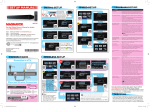
User Manual for the
GSM StreetLight
Software
Rajtek Technical Support
This reference manual describes the capabilities of the
software and the range implemented commands needed
for remote control of street lighting over the GSM.
RAJTEK
Janko Cvetinov 13, Strumica,
Macedonia
+389 34 344664
Revision: 1.0
www.raj-tek.com
18
RAJTEK
DATE: 11/29/2012
REVISION: 1.0
www.raj-tek.com
19
RAJTEK
DATE: 11/29/2012
REVISION: 1.0
www.raj-tek.com
Contents
1. Main user interface description
2
1.1.
Information bar and database record area
3
1.2.
Command buttons, option buttons and active selection area
5
2. Adding a new record – new client in the database
7
3. Editing or creating a script
9
4. Working with the energy log
11
5. Working with the sun calendar
12
6. Managing an unsent SMS
14
7. Starting the application
16
1
RAJTEK
DATE: 11/29/2012
REVISION: 1.0
www.raj-tek.com
1. Main user interface description
1
2
4
3
5
6
7
8
9
10
22
11
12
21
13
14
15
20
16
19
18
17
Picture 1. Main user interface appearance
The above picture shows the appearance of the main user interface with its commands and
different information areas. In the following paragraphs each of the command buttons and
information areas will be described and explained.
Before we start, it is very important that the user is introduced to the color coding schema of
the user interface. Namely, it is evident that there are three types of buttons:
•
•
•
•
Dark Blue Wide
Dark Blue Short
Light Blue
Yellow
The Dark Blue Wide buttons are for functionalities of the software where the GSM is not
used, i.e. where SMS messages are not being sent.
2
RAJTEK
DATE: 11/29/2012
REVISION: 1.0
www.raj-tek.com
The Dark Blue Short buttons present the user with selection of an option or display an
existing option on the client’s side. When an option is activated by clicking on the button or
when these buttons present the user with an active existing option on the client’s side, they will
change to green, as shown
.
The Light Blue buttons are used for direct commands. When any of these buttons is clicked
it will immediately trigger an SMS message to the client, either directing it to execute a
command or requiring a response.
The Yellow buttons are for information purposes, only. When clicked, it will display auxiliary
information, not of operational importance to the software but important from a point of view
of the user.
Let us now describe the different areas of the user interface, as enumerated on Picture 1.
1.1.
Information bar and database record area
1. This icon displays the state of registration of the SIM card and the signal strength. In case
the SIM card is not registered on the GSM network even if the signal strength is good
enough, the software will not be capable of sending text messages.
2. This part of the information bar displays network operator information. The software will
continuously search for network operator until one is identified. In case network operator is
not identified no text messages can be sent.
3. This area displays the network provider.
4. The current time and date are displayed in this label. The software constantly compares the
time and date of the GSM modem with the time and date of the working station PC on
which the software has been installed. In case there is a difference of more the one second
the software will automatically change the time and date of the GSM modem, in which case
the label will write “Synchronizing…”.
NOTE: THE REFFERENCE TIME AND DATE IS THE COMPUTER’S TIME AND DATE ON
WHICH THE SOFTWARE IS RUNNING. IT IS USER’S RESPONSIBILITY TO
SUPPLY THE CORRECT TIME AND DATE OF HIS WORKING STATION.
5. This label indicates the communication port number as well as its state. In case
communication with the GSM modem is functioning properly, the blue light indication will
flash every ten seconds. By clicking on this label, the user can change the port number
through which the PC communicates with the GSM modem.
6. The light indicators in this area of the information bar are connected to the hardware states
of RS232 communication lines: Clear to send line, Data ready line, Receive and Transmit
lines. When the hardware communication lines function properly, the CTS and the DSR line
3
RAJTEK
DATE: 11/29/2012
REVISION: 1.0
www.raj-tek.com
will constantly flash. The TX and the RX lines will flash only wh
hen the software is
transmitting or receivingg, accordingly. In case there is a hardware communication then the
ERR indication will contiinuously flash until a correct communication is established. The user
should note that the ERR
E indication will not flash if there is total malfunction with the
communication port and the port cease to exist (for example, if the communication
c
cable
gets plugged off). In this
is situation, the user will see that there will be not network.
rrently being sent. It
7. This area shows a progrress bar indicating the progress of the SMS curr
appears only while an SM
MS is being sent.
8. The icons in this area indicate
i
the state of the sent and received SMS. When an SMS is
received the informatio
ion bar will briefly display the letter
icon
n. If the required
format of the received SMS is not recognized the software will autom
matically discard this
SMS and briefly displayy the “Not Recognized Format”
icon. In case the format of
the SMS is recognized but
b there is a consistency error, then the “Wron
ng Format” icon
will be displayed. Whe
en sending an SMS, if the sending process failss for any reason, the
“Failed SMS”
icon iss displayed. When visible, this icon has an additio
ional functionality. If
the mouse is positioned over this icon a text informing the user of the to
otal number of failed
SMS’s will be displayed.. If this icon is clicked, the application will open a window indicating
the failed SMS list. The functionality of this part of the user interface is described
d
in Chapter
6.
m’s window DC. It is
9. This area is not part of the information bar but of the operating system
used to minimize the win
indow or terminate the program.
u
interface that displays the existing databasse. Besides the self10. This is the area of the user
explanatory column cap
ptions, the first column caption is labeled “ID”.. This is an internal
record identification nu
umber, not volatile by the user and unique forr each record in the
database. The fields in the
t column ID contain additional information, im
mportant to the user.
First of all there is the ch
heck box field. When checked, it indicates that this
t item should also
be taken in consideratiion when executing a command. If multiple items
it
are check, the
selected command will be
b executed on all of the selected (checked) item
ms. The user should
note that clicking any row
r
on this list (except the first row) makes the client active. This
means even if no clientt is checked, a command will be executed upon this client. The user
can see his selection verrification in the fields marked by the item numbeer 20.
Additional information contained
c
in the field ID is the status of the scrript uploaded to the
client. If the
iccon is displayed it means that the client has an active script and the
last known information is that the script is running. If the icon
is displayed,
d
it means
that the client has an uploaded
u
script, but last known information is that
t
the script is not
running. If the icon
is displayed, it means that the client has no up
ploaded user defined
script and hence script is not running.
NOTE: ON THE CLIENT SIDE, EVEN THOUGH THERE MAY BE NO
O SCRIPT UPLOADED
BY THE U
USER OR AN UPLOADED SCRIPT HAS BEEN DELET
TED, THE CLIENT HAS
4
RAJTEK
DATE: 11/29/2
2012
REVISION: 1.0
www.raj-tek.com
A HARD-WIRE IMPLEMENTED FAIL-SAFE SCRIPT WHICH ALLOWS IT A BASIC
AND FAIL-SAFE FUNCTIONALITY.
The columns “Consumption” and “Date” change its value every time the user requires new
status. In other words, these fields display the last know consumption status of the client.
NOTE:
THE SHOWN CONSUMPTION STATUS OF THE CLIENT AND THE VALUE
WRITTEN IN THE DATABASE WILL NOT BE CHANGED UNLESS MANUALLY
REQUIRED BY THE USER. ONLY THE LAST VALUES WILL BE DISPLAYED HERE.
FOR HISTORICAL CONSUMPTION REQUIREMENTS SEE CHAPTER 4.
1.2. Command buttons, option buttons and
active selection area
11. This push button opens a window with a list of all required consumption states, of all the
clients, in a chronological order. For details see Chapter 4.
12. As previously described, this push button according to the applied color schema belongs to
direct commands. When pressed, it immediately sends an SMS or multiple SMS’s to the
selected client or clients requiring of them to inform the base of their current consumption
state. The selection can be done in two ways. If there are checked items in the clients’
database, then the software scrolls through all of the checked items and sends the
command to each of them. Otherwise, it will send the command only to the currently
selected client. Information about currently selected client is placed in the fields of item 21.
In case nothing is checked and there is not a current client selection, a message box will
inform the user that this command will not be executed.
13. When pressed, this button opens the script editor. For details on creating a script see
Chapter 3.
14. When pressed this button immediately sends an SMS to the client requiring of it to send the
script saved in its memory. The script may exist, not exist, be active or not be active. No
matter, the client will respond with an SMS. For details on creating or modifying a script see
Chapter 3. This command does not support multiple client executions, meaning it will
execute only on the currently selected client.
15. The” Sync R.T.C.” (Synchronize Real-Time Clock) button sends a synchronization SMS to the
client. The contents of this SMS are the current time and date of the base station (the PC on
which this software is installed), directing the client to change its time and date to the ones
indicated. This command supports single client as well as multiple client execution.
5
RAJTEK
DATE: 11/29/2012
REVISION: 1.0
www.raj-tek.com
16. The “Sun Calendar” button belongs to the group of auxiliary information buttons. When
pressed, it will open a window showing the calendar of sunrise and sunset on different
locations. For details see Chapter 5.
17. Even though this task bar does not belong to this logical group (it is not a button, but an
information bar) for enumeration consistency, it is described here. This area is a task bar
area that shows the last executed action by the GSM modem.
18. The “Execute” command button is directly connected to the “Select State” option buttons.
It directs the client to immediately turn on or off each of its phases. This command supports
single client as well as multiple client execution.
NOTE:
WHEN A MANUAL ON/OFF EXECUTION IS CARRIED OUT THE CLIENT
RESPONDS IMMEDIATELY, SUSPENDING ALL INTERNAL ACTIVE SCRIPTS!
WHEN USING MANUAL EXECUTION THE USER IS URGED TO CONSIDER THE
EXISTING ENVIRONMENT AND JUSTIFICATION OF MANUAL EXECUTION. IN
ORDER TO ACHIEVE FAIL-SAFE OPERATION THE CLIENT HAS A BUILT-IN
SAFETY MECHANISAM. NAMELY, EVERY MANUAL EXECUTION IS ACTIVE
UNTIL 06:00 IN THE MORNING. WHEN THE R.T.C. REACHES THIS TIME, THE
MANUAL COMMAND IS IMMEDIATELY SUSPENDED AND CONTROL OF
OPERATION IS RETURNED TO THE ACTIVE SCRIPT.
19. This command requires of the client to inform of its current phase state. The new received
phase state will be immediately indicated on the “Select State” option buttons and this
information will be saved in the database. In case of multiple client execution, the new
phase state will be indicated after making client selection from the clients’ list. This
command supports single client as well as multiple client execution.
20. These option buttons R, S and T represent the phases of the client. They have double
functionality. The R, S and T option buttons show the last known phase state of the client,
but also enable the user to indicate a new state and activate this state by manual execution.
21. This is the area where information of currently selected client is shown. A record from the
database (the clients’ list) is made a current selection by clicking on the desired row from the
clients’ list. This area consists of the following self-explanatory fields: “ID”, “Name”,
“Address”, “Tel. No.”, “Energy”, “Power Const.” and “On Date”.
22. When there is an active client selection, pressing this button will display a window with a list
of all ever required energy states of this single, currently selected, client. Compared to the
button from point 11, this one has essentially the same functionality but showing
information for a single client, only.
6
RAJTEK
DATE: 11/29/2012
REVISION: 1.0
www.raj-tek.com
2. Adding a new record – new client
in the database
In this section we will describe how to insert a new client in the database. This operation is very
straight forward and should not present the user with any difficulties.
The picture below shows the appearance of the “Add New Record” form.
Picture 2. Add New Record form
The first three fields, “Station Name”, “Station Address” and “Power Constant” are
descriptive fields that have no influence on the software operation. These fields visually assist the
7
RAJTEK
DATE: 11/29/2012
REVISION: 1.0
www.raj-tek.com
user. Even though they do not influence software operation, they never the less contain information
very important to the user.
The next field is the telephone number. This field most directly influences the operation of
the software and the grid itself. This is the telephone number used when sending an SMS to the
client (the station) and as such should represent unique client identifier. The telephone number
should be entered together with the country code and the area code (operator code).
NOTE: IT IS ON THE RESPONSIBILITY OF THE USER TO USE UNIQUE TELEPHONE
NUMBERS FOR EACH STATION. IF THIS IS NOT THE CASE IT MAY LEAD TO
AMBUGUITIES.
The next section has three logically separated entities. These are marked with large R, S and
T letters. This is the area where the working client script should be entered. These fields are not
obligatory to be specified at this point.
Each of the three entities has ten fields. These represent the ten memory locations
allocated for the script of the according phase. This means that to each phase, within twenty four
hours, total of five on/off actions can be defined. Hence, these fields should contain the times when
each phase should be turned on (fields in the “On Time” column) and turned off (fields in the “Off
Time” column). The hour format that should be used is “hh:mm” – two digits for the hour and two
digits for the minutes separated by a colon. The software has an implemented routine to check for
correct syntax. Nevertheless, the user is also urged to use the correct syntax.
When the user is satisfied with the entered information, the “Add Record” button should be
pressed. By doing so, the software make a logical information check and enters the date in the
database.
NOTE: IT SHOULD BE EMPHASIZED THAT THE INFORMATION IN THE FIRST FOUR
FIELDS (“NAME”, “ADDRESS”, “POWER CONSTANT” AND “TEL. NUMBER”)
CAN NOT BE CHANGED LATTER ON. THE ONLY WAY IS TO DELETE THE
RECORD FROM THE DATABASE AND MAKE A NEW RECORD. THE USER
SHOULD TAKE GREAT CARE WHEN ENTERING CLIENT INFORMATION. THE
RESPONSIBILITY FOR THE INFORMATION ENTERED AND HOW THIS
INFORMATION IS USED HAS THE USER, SOLELY! MOREOVER, IF THERE HAVE
BEEN ACTIONS EXECUTED UPON A CERTAIN CLIENT AND LATTER ON THE
CLIENT IS ERASED, ALL OF THE HISTORY FOR THAT CLIENT WILL BE ERASED
ALONG WITH IT.
After the data is added to the database, the software will wait for a new input. In case new
input is not required, the “Close” button should be pressed. The same is achieved by simply closing
the active window.
8
RAJTEK
DATE: 11/29/2012
REVISION: 1.0
www.raj-tek.com
3. Editing or creating a script
In this section it will be explained how the user can attach (create) or edit a script for a client.
When the “Script Edit” button on the main user interface is pressed (point 13, Picture 1) the
following form is displayed.
Picture 3. Script Editor form
Similarly to the previous chapter, the first section of this form has three logically separated
entities. These are marked with large R, S and T letters. This is the area where the working client
script should be entered.
Each of the three entities has ten fields. These represent the ten memory locations
allocated for the script of the according phase. This means that to each phase, within twenty four
hours, total of five on/off actions can be defined. Hence, these fields should contain the times when
each phase should be turned on (fields in the “On Time” column) and turned off (fields in the “Off
9
RAJTEK
DATE: 11/29/2012
REVISION: 1.0
www.raj-tek.com
Time” column). The hour format that should be used is “hh:mm” – two digits for the hour and two
digits for the minutes separated by a colon. The software has an implemented routine to check for
correct syntax. Nevertheless, the user is also urged to use the correct syntax.
NOTE: THE VALUE “00:00” IS RESERVED FOR “EMPTY FIELD”. THE USER SHOULD
NOT USE THIS VALUE SINCE IT WILL HAVE THE SAME EFFECT AS AN EMPTY
FIELD.
In addition to every memory set of on/off values, there is an option button where the user
can specify if the uploaded script should be activated immediately after the upload has finished or
not. The memory set of the script cannot be activated unless both on and off times are correctly
specified.
The user is also provided with an option to save the currently written script or even pick up
one that has previously been saved. By pressing the “Save” button the user will be asked for a
location and name by which the script will be saved. Even though there is a default directory for
saving the scripts, the user can save them anywhere. If latter on the script needs to be recalled, the
“Browse” button should be pressed. The path and name of the selected script will be shown on the
label above the “Save” and “Browse” buttons.
When the script has been created and needs to be transferred to the client the user should
press the “Update” button. By pressing this button, the script is saved in the database, immediately
an SMS with the script is sent to the client and the script status icon in the “ID” column of the clients’
list is updated.
Pressing the “Cancel” button closes the script editor. This can also be achieved by simply
closing the script editor window.
10
RAJTEK
DATE: 11/29/2012
REVISION: 1.0
www.raj-tek.com
4. Working with the energy log
Each time the user presses the “Get Consumption” button (point 12, Picture 1) the received date
is saved in the database. This way, the user can have a history of energy consumptions of every
client. The energy log can be brought up by pressing any of the two “Energy Log” buttons on the
main user interface form (point 11, point 22, Picture 1). The difference between the two has been
explained in Chapter 1.2. The displayed data is in chronological order.
Picture 4. Energy Log form
This form has just one additional option. This is exporting the listed information to an ASCII
file for further processing. This date is exported in such a way that can be easily imported in any
data processing or office application, such as Excel. When this button is pressed the application will
ask the user for the path and name under which the exported data will be saved.
11
RAJTEK
DATE: 11/29/2012
REVISION: 1.0
www.raj-tek.com
5. Working with the sun calendar
In order to provide the user with a tool to created more efficient scripts, this application has
been provided with a sun calendar calculator. It has implemented locations for almost all the largest
cities of the Republic Of Macedonia. At this moment this database of latitudes and longitudes is
fixed, but in the further updates it will be an open database allowing the user to insert one’s own
locations.
The sun calendar calculator form is activated by pressing the “Sun Calendar” button (point 16,
Picture 1).
Picture 6. Sun (sunset-sunrise) calendar form
The first thing the user needs to do is to select a location. This can be done by selecting one
from the “City” drop down list. The application will automatically show the sunrise and sunset times
12
RAJTEK
DATE: 11/29/2012
REVISION: 1.0
www.raj-tek.com
on the according labels for the desired location on the current date, which by default is the current
date of the PC. From the calendar form, the user can select a different date. Changing the date will
automatically update the sunrise and sunset times.
There is also an option button named “Daylight Saving Time”. The user can select if daylight
saving time is applicable for the current location or not.
In order to further assist the user, the sun calendar form shows a graph of the sunrise and
sunset times in a period of 365 days, starting from the current date. The red line marks the sunrise
time and the blue the sunset times. Moving the mouse over this graph the user can see the date
over which the mouse icon is. This date is shown on the label below the graph.
NOTE: THE SUNRISE AND SUNSET TIMES SHOWN ON THE CALENDAR FORM ARE
CALCULATED TIMES ACCORDING TO INTERNATIONALLY RECOGNIZED
ASTRONOMICAL CALCULATIONS.
THESE CALCULATIONS TAKE
CONSIDERATION ONLY OF THE LATITUDE AND LONGITUDE OF THE DESIRED
LOCATION AND THE DATE. THE USER SHOULD CONSIDER THAT THE
APPARENT SUNRISE AND SUNSET TIMES DEPEND TO A DIFFERENT EXTENT
ON THE TOPOGRAPHY OF THE SURROUNDING, AND AS SUCH MAY DIFFER
FROM THE ASTRONOMICAL SUNRISE AND SUNSET TIMES BY A FEW
MINUTES.
13
RAJTEK
DATE: 11/29/2012
REVISION: 1.0
www.raj-tek.com
6. Managin
ng an unsent SMS
An SMS may fail for many different reasons, such as network failure, con
nnection failure, SIM
registration failure, etc. In orde
er that the information transmitted through the
e SMS is not lost, in
case it cannot be sent, the application informs the user of the unsuccessful diispatch and puts the
information contained in the SMS
S
on the failed SMS stack. When an SMS cannot be sent the
application will not attempt to send
s
it again, automatically. This is due to safetty reasons. The user
has to confirm re-sending of anyy SMS.
When SMS fails, the “Failed
d SMS” icon
is shown in the information barr of the main screen
(point 8, Picture 1) indicating thaat the application requires user attention. If the mouse is positioned
over this icon a text informing the
t user of the total number of failed SMS’s willll be displayed. If the
icon is clicked, the software willl open a window indicating the failed SMS list, as shown
s
on Picture 7.
Picture 7. Un
nsent SMS form showing the list of unsent SMSs
The list in this window con
ntains information about the client the SMS was
w intended for, its
phone number and the comman
nd that was supposed to be executed. When thee user double-clicks a
row, the application will try to resend
r
the SMS immediately after positive confo
ormation by the user
that an SMS is about to be sen
nt containing the information of the previously unsent SMS. If this
action is successful the SMS wiill be deleted from the stack (the list). Otherwise, the user will be
informed of the failure but the SMS will not be added to the stack again. This
is is done in order to
avoid same message accumulatiion.
In case the user does not want
w
to resend one or more SMS then these messages should be
checked on the list and the buttton “Delete marked” should be pressed. When all the unsent SMS’s
14
RAJTEK
DATE: 11/29/2
2012
REVISION: 1.0
www.raj-tek.com
need to be deleted, the user should check the option button “Mark All” and then press “Delete
marked”.
NOTE: THE FAILED SMS STACK IS MAINTAINED ONLY AS LONG AS THE APPLICATION
IS RUNNING. WHEN THE APPLICATION CLOSES THE FAILED SMS STACK IS
RESET.
15
RAJTEK
DATE: 11/29/2012
REVISION: 1.0
www.raj-tek.com
7. Starting the application
When the application starts the first thing it does is to search for communication ports. It
collects all the existing serial port numbers and asks the user to make a selection. In the situation
where no serial ports are found the application will not start and inform the user that serial ports
were not found. When communication ports exit, the following form will be shown.
Picture 8. Serial Communication port selection form
The user should select one of the serial communication port numbers and press the “Select”
button. The user will be asked to select a communication port only if:
•
•
•
It is the first time the application is running;
There has been a change in the hardware configuration of the personal computer and the
previously selected communication port does not exist anymore;
The user has decided to change the communication port number by clicking the “Comm”
label on the information bar of the main user interface (point 5, Picture 1).
After the serial communication port has been successfully selected, the application will ask for
user name and password, as shown below.
Picture 9. Login window
Even though the application does not have user privileges administration implemented, it
still requires from the user to register one self and enter a password that has to match the one that
has been hard-coded in the software. This password will be given to the user by the software
supplier. At this point, this data is for informative purposes, only. It is not used for any user
administration. In the future updates of this software, user privileges administration will be
implemented to the fullest extent.
Pressing the “Ok” button will continue with software start-up. Pressing the “Cancel” button
will terminate the application.
After the correct password has be entered, the application will show the main user
interface, as shown in Picture 1, and will try to establish a communication connection with the GSM
16
RAJTEK
DATE: 11/29/2012
REVISION: 1.0
www.raj-tek.com
modem. At the same time, the application will check if it is registered with the software supplier. If
the application has not been registered or the registration information is incorrect, the application
will wait until connection with the GSM modem has been established and then a registration
window will appear asking the user to register the software.
Picture 10. Product Registration window asking from the user to register the software
By pressing the register button the application sends an SMS to the Rajtek Technical Support
center asking to be registered. This registration process may take up to ten minutes. While in
progress, the following will be shown.
Picture 10. Product Registration window showing registration in progress
The progress bar lights with dark blue color will sequentially light up, indicating that
registration is in progress. If in the meantime the user clicks the “Cancel” button, the application will
be terminated. However, even if the application is not running, as long as the GSM modem is active,
the registration process is still going to be finished. The next time the application starts, it will
confirm the registration information and proceed to the main user interface.
When the registration has been finished previously, and the application is not run for the
first time, the main user interface will show immediately after successful login.
17
RAJTEK
DATE: 11/29/2012
REVISION: 1.0