1
C UBE OS
A COMPONENT- BASED OPERATING SYSTEM
FOR AUTONOMOUS SYSTEMS
H OLGER K ENN
A RTIFICIAL I NTELLIGENCE L ABORATORY
V RIJE U NIVERSITEIT B RUSSEL
AUGUST 2001
C UBE OS
A COMPONENT- BASED OPERATING SYSTEM
FOR AUTONOMOUS SYSTEMS
H OLGER K ENN
A RTIFICIAL I NTELLIGENCE L ABORATORY
V RIJE U NIVERSITEIT B RUSSEL
P ROEFSCHRIFT
VOORGELEGD VOOR HET BEHALEN VAN DE ACADEMISCHE
GRAAD VAN DOCTOR IN DE WETENSCHAPPEN , IN HET OPENBAAR TE
VERDEDIGEN OP
27 AUGUSTUS 2001
Promotiecommissie:
P ROMOTOR :
VOORZITTER :
S ECRETARIS :
OVERIGE LEDEN :
P ROF. DR . L. S TEELS , V RIJE U NIVERSITEIT B RUSSEL
P ROF. DR . D. V ERMEIR , V RIJE U NIVERSITEIT B RUSSEL
P ROF. DR . A. B IRK , V RIJE U NIVERSITEIT B RUSSEL
P ROF. D R . K URT M EHLHORN , MPI F ÜR I NFORMATIK , S AARBR ÜCKEN
D R . H. B RUYNINCKX , K ATHOLIEKE U NIVERSITEIT L EUVEN
P ROF. DR . H. S AHLI , V RIJE U NIVERSITEIT B RUSSEL
Acknowledgments
First, I want to thank my advisors. Andreas Birk gave me the opportunity to work with him in
an international environment on the topic of autonomous systems and artificial intelligence although I had not worked in this area before. During my time in his research group, I could complete my knowledge in computer architecture and system software engineering and I learned
many new and interesting things from the research on the origins of intelligence. Also, I am
very grateful for the opportunity to work with Luc Steels in his AI Lab. Although I am not
directly involved in his research on the origins of language, I had many fruitful discussions
with him and with other members of the lab over related topics and again, I learned a lot.
Also, I want to thank Prof. Dr. Kurt Mehlhorn and Dr. Ir. Herman Bruyninckx who agreed to
act as external members of the Ph.D. committee and to the VUB members of the committee,
Prof. D. Vermeir and Prof. Dr. H. Sahlim.
Thanks to the other members of the lab, Tony Belpaeme, Joachim De Beule, Karina Bergen,
Edwin De Jong, Joris Van Looveren, Dominique Osier, Paul Vogt, Jelle Zuidema and especially to Thomas Walle with whom I had endless discussions over various aspects of Hard- and
Software. Although I could rarely convince him of my views, I did learn a lot from him.
Also, I thank all the beta-testers of CubeOS, the students and the researchers from other universities and the people at Quadrox N. V. and ProSign GmbH that looked at my code and told
me where the bugs were.
I also like to thank my parents, Anni and Wolfgang Kenn for supporting me, not only financially, but for giving me the mental support necessary to survive a Ph.D. I also like to thank the
people at the MPI für Informatik, espechially at the Computer Service Group for showing me
that there is a practical side to computer science and supporting me in various projects. Last
but not least, I’d like to thank Heiko Kamp and Oliver Kohlbacher for staying in touch with me
while we’re all spread over the world.
v
Contents
Acknowledgments
v
Abstract
xi
Introduction
xv
1
Autonomous Systems
1
1.1
Design of autonomous systems . . . . . . . . . . . . . . . . . . . . . . . . . .
3
1.1.1
Software-design techniques . . . . . . . . . . . . . . . . . . . . . . .
3
1.1.2
Realtime design techniques . . . . . . . . . . . . . . . . . . . . . . . .
4
1.1.3
Robot design . . . . . . . . . . . . . . . . . . . . . . . . . . . . . . .
6
Implementation of autonomous systems . . . . . . . . . . . . . . . . . . . . .
9
1.2
1.3
1.2.1
Computational hardware . . . . . . . . . . . . . . . . . . . . . . . . . 10
1.2.2
Programming language for system software implementation . . . . . . 11
Operating system services for autonomous systems . . . . . . . . . . . . . . . 11
1.3.1
Multithreading . . . . . . . . . . . . . . . . . . . . . . . . . . . . . . 13
1.3.2
Scheduling repetitive tasks . . . . . . . . . . . . . . . . . . . . . . . . 20
1.3.3
Inter-thread communication and synchronization . . . . . . . . . . . . 31
1.3.4
Mutexes, spin-locks and semaphores . . . . . . . . . . . . . . . . . . . 33
1.3.5
Priority inversion . . . . . . . . . . . . . . . . . . . . . . . . . . . . . 36
vii
1.4
1.5
2
direct hardware access . . . . . . . . . . . . . . . . . . . . . . . . . . 38
1.3.7
realtime clock . . . . . . . . . . . . . . . . . . . . . . . . . . . . . . . 39
1.3.8
initialization and configuration . . . . . . . . . . . . . . . . . . . . . . 42
Communication services for autonomous systems . . . . . . . . . . . . . . . . 43
1.4.1
wireless communication . . . . . . . . . . . . . . . . . . . . . . . . . 44
1.4.2
modulation and data encoding . . . . . . . . . . . . . . . . . . . . . . 45
1.4.3
Media Access Methods . . . . . . . . . . . . . . . . . . . . . . . . . . 45
1.4.4
high-level data encoding . . . . . . . . . . . . . . . . . . . . . . . . . 46
Conclusion . . . . . . . . . . . . . . . . . . . . . . . . . . . . . . . . . . . . 47
Operating system design
2.1
2.2
3
1.3.6
Operating Systems . . . . . . . . . . . . . . . . . . . . . . . . . . . . . . . . 49
2.1.1
Monolithic kernel operating systems . . . . . . . . . . . . . . . . . . . 50
2.1.2
Micro-kernel and modular operating systems . . . . . . . . . . . . . . 53
2.1.3
Nanokernels and virtual machines . . . . . . . . . . . . . . . . . . . . 55
2.1.4
object oriented operating systems . . . . . . . . . . . . . . . . . . . . 56
2.1.5
component operating systems . . . . . . . . . . . . . . . . . . . . . . 57
2.1.6
Realtime operating systems . . . . . . . . . . . . . . . . . . . . . . . 59
2.1.7
Exception handling . . . . . . . . . . . . . . . . . . . . . . . . . . . . 60
Conclusion . . . . . . . . . . . . . . . . . . . . . . . . . . . . . . . . . . . . 63
The CubeOS Kernel
3.1
49
65
Hardware: The RoboCube . . . . . . . . . . . . . . . . . . . . . . . . . . . . 65
3.1.1
CPU . . . . . . . . . . . . . . . . . . . . . . . . . . . . . . . . . . . . 66
3.1.2
System . . . . . . . . . . . . . . . . . . . . . . . . . . . . . . . . . . 67
3.1.3
Busses . . . . . . . . . . . . . . . . . . . . . . . . . . . . . . . . . . 70
3.2
3.1.4
i/o interfaces . . . . . . . . . . . . . . . . . . . . . . . . . . . . . . . 70
3.1.5
intelligent devices . . . . . . . . . . . . . . . . . . . . . . . . . . . . 72
3.1.6
boot monitor . . . . . . . . . . . . . . . . . . . . . . . . . . . . . . . 73
Software Environment . . . . . . . . . . . . . . . . . . . . . . . . . . . . . . 74
3.2.1
3.3
The global design of RoboCube . . . . . . . . . . . . . . . . . . . . . . . . . 77
3.3.1
3.4
4
Details of the C language implementation of GCC for the RoboCube
CPU . . . . . . . . . . . . . . . . . . . . . . . . . . . . . . . . . . . . 75
CubeOS components . . . . . . . . . . . . . . . . . . . . . . . . . . . 77
Detailed aspects of the implementation . . . . . . . . . . . . . . . . . . . . . . 85
3.4.1
System configuration . . . . . . . . . . . . . . . . . . . . . . . . . . . 85
3.4.2
Abstract datastructures . . . . . . . . . . . . . . . . . . . . . . . . . . 85
3.4.3
Interrupt service routine implementation . . . . . . . . . . . . . . . . . 87
3.4.4
The multi-threading scheduler and context switch implementation . . . 87
3.4.5
time delay and communication i/o . . . . . . . . . . . . . . . . . . . . 96
3.4.6
semaphores and priority inversion avoidance . . . . . . . . . . . . . . 97
3.4.7
exception processing and recovery . . . . . . . . . . . . . . . . . . . . 97
Application of CubeOS
99
4.1
reusable components: RobLib . . . . . . . . . . . . . . . . . . . . . . . . . . 99
4.2
interpreter for visual control block architecture: icon-L . . . . . . . . . . . . . 102
4.3
semi-autonomous architecture: RoboGuard . . . . . . . . . . . . . . . . . . . 105
4.4
4.3.1
Components and Integration of the Mobile Base . . . . . . . . . . . . 107
4.3.2
The Control Software . . . . . . . . . . . . . . . . . . . . . . . . . . . 108
4.3.3
RoboCube Software Drivers and Operating System Support . . . . . . 108
4.3.4
The Strategic and Path-Planning Layers . . . . . . . . . . . . . . . . . 110
distributed architecture: RoboCup . . . . . . . . . . . . . . . . . . . . . . . . 111
4.5
4.4.1
Classification of Team-Approaches . . . . . . . . . . . . . . . . . . . 112
4.4.2
Towards a Robot Construction-Kit . . . . . . . . . . . . . . . . . . . . 114
4.4.3
Using the RoboCube for Highlevel Control . . . . . . . . . . . . . . . 115
Advanced behavior-oriented architecture: NewPDL . . . . . . . . . . . . . . . 119
4.5.1
The Process Description Language (PDL) . . . . . . . . . . . . . . . . 120
4.5.2
simulation of a nPDL system for debugging . . . . . . . . . . . . . . . 125
4.5.3
postmortem analysis of a running program
. . . . . . . . . . . . . . . 125
Abstract
In this thesis, research about software design for autonomous systems is presented. A
component-based operating system has been designed that has many special features which
support the rapid development of autonomous systems for various applications.
These special features are:
• a new scheduler for simple control tasks that optimizes the regular execution over wide
timespans,
• drivers for various common sensors and actuators,
• an efficient implementation of general-purpose operating system services that respects
the limited hardware resources on autonomous systems,
• and support for high-level components for various common problems, e.g. a component
to control differentially-driven mobile robots.
This operating system, CubeOS has been implemented from scratch for the so-called
RoboCube, a newly-designed embedded control computer based on the Motorola MC68332
MCU.
CubeOS and the RoboCube have been successfully used in various applications ranging from
teaching and various research applications to an industry project.
xi
“I think that the most exciting computer research now is partly in robotics, and
partly in applications to biochemistry.”
Donald Knuth
Introduction
As with most other open-source projects, the initial reason to start CubeOS was frustration over
the available software. It occurred after completing the design phase of the RoboCube[BKW98]
hardware architecture which is a modular embedded controller for autonomous systems. There
was no adequate operating system that could make use of the unique modularity of the new
hardware. Moreover, there was a wide field of possible applications for the new architecture,
ranging from teaching over industrial applications[BK01b] to experiments about multi-robot
cooperation[McF94, Ste94] and the emergence of language[Vog98]. A stable operating system
is a requirement for all these applications. Unfortunately, neither available open-source nor
commercial implementation would perfectly fit.
The drawback of the commercial operating systems are that every developer needs a separate
development license which is quite expensive. Although there were special reductions for
academic use, these academic licenses could not be used in the context of an industry project.
Another drawback was the focus on traditional embedded and realtime applications in which
a system is once designed from specifications and is then mass-produced. This contradicts the
approach found in the academic environment, where an operating system is used as the basis for
multiple software environments such as nPDL[BKS00] on top of which different application
programs are implemented.
From the available open-source operating systems, most of them did only support widelyavailable hardware such as PCs. Even systems that did support hardware similar to the
RoboCube were lacking all the special functions such as the modularity that were needed for
our applications. Moreover, many open-source operating system projects suffer from poor design, poor documentation and “featurism”. There were some exceptions, e.g. RTEMS[RTE]
and eCos[eCo] but unfortunately, RTEMS was too much focussed on classic realtime approaches and eCos does not support the CPU architecture of the RoboCube.
From this, it was decided to design and implement a new operating system for autonomous
systems.
Designing an operating system for autonomous systems led to some unique challenges that
were not adressed in existing systems. One of them was scheduling repetitive executions.
Conventional schedulers for general-purpose operating systems rely on the fact that most of
xv
the time, the system is i/o bound, i.e. the system is either waiting for user interaction or for
an i/o operation to complete. By sorting the tasks according to a fixed or dynamic priority
value and running the highest-priority non-blocking task, these systems can acchieve good
overall system performance. However, the way autonomous systems are designed leads to the
situation that there is not such a high amount of idle time in higher priority tasks, therefore,
lower priority tasks would hardly be run.
To overcome this situation, a novel type of scheduler has been designed that guarantees execution frequency ratios between tasks of different priority.
The unique modularity and the huge ammount of different hardware devices involved in the
physical design of autonomous systems make the design process of an autonomous system a
complex task. Therefore, the operating system should support the user and add as few complexity to the design task as possible. As a consequence CubeOS has been designed as a component
system in which the designer of an autonomous system can construct an operating system that
exactly fits the autonomous system that it is constructed for. Only the components needed are
included, others are left out automatically and the designer can implement additional components if necessary.
Chapter 1
Autonomous Systems
In this chapter, the general design considerations for the CubeOS operating system are presented that result from the application domain of autonomous systems. From this, a list of
necessary operating system services is compiled and presented in detail.
According to [Bir01], an autonomous system is a combination of:
• a computational core
• network connections
• sensing and effecting subsystems
• a finite resources store
• a guiding control
What are the requirements for an operating system for an autonomous system?
First of all, an autonomous system has to act more or less without external supervision for
extended periods of time. So the operating system should also require as few maintenance
as possible. Moreover, it should be highly stable since it cannot rely on a human operator as
last resort. In the event of a failure, the system should either recover from it (failure-tolerant,
“self-healing”) or bring everything to a safe state so that no further damage results.
The resources of an autonomous system are constrained. One example is electrical power, another one is size and weight. As a result, the on-board computer of the autonomous system
is constrained in computation power and memory. An operating system for autonomous system should therefore be as efficient as possible to leave as many resources as possible to the
application program.
1
2
CHAPTER 1. AUTONOMOUS SYSTEMS
Another important aspect is that the guiding control of an autonomous system has to deal with
complex situations. Therefore, the design goal for the implementer of such a system is to make
it able to work under these complex circumstances, usually resulting in a rather complex system
design. The operating system should reduce the complexity of this task. For that, the operating
system should be simple and should work in a transparent way.
Many parts of the system are only used for specific applications, e.g. driver software is only
used if the corresponding hardware is present in the system. Therefore, the operating system
should be designed in a modular way and the implementer should be able to customize it, so
that it provides the functions necessary for the application but nothing more.
One field where this customization is very important is the domain of sensors and actuators.
The operating system should contain functions to access various kinds of these devices with
the option to add more that are specific to the application.
An important task of an autonomous system is the reaction to the world around it in a timely
manner. Therefore, the operating system has to provide functionality to deal with real time
events and timing constraints.
In the following sections, these requirements are inspected in detail and various approaches of
their implementation are discussed.
A example for an autonomous system is a mobile robot operating independently in a unstructured environment. This will be the standard example of an autonomous system throughout the
next chapters although many other classes of autonomous systems are possible. However, the
mobile robot is a good example since it includes all features of an autonomous system and is
useful to present the common problems of autonomous system design.
• A mobile robot has a finite resource store, i.e. limited onboard batteries.
• It has a small onboard computer for control.
• Most mobile robots have some mean of communication, either with an operator or other
mobile robots.
• It has onboard sensors, i.e. distance sensors or bump switches.
• It has onboard actuators, at least to move the robot itself, often also additional manipulators.
Mobile robots of this type are often used in academic research. Some applications are presented
in Chapter 4.
1.1. DESIGN OF AUTONOMOUS SYSTEMS
3
1.1 Design of autonomous systems
To analyze the requirements for an operating system for autonomous systems, design techniques for autonomous systems are reviewed and from this, the necessary features of the operating system are derived. There are no design techniques that are specific to autonomous
systems. However, the design of an autonomous system can benefit from design techniques in
various related fields.
1.1.1 Software-design techniques
There are various software design techniques that can be applied to autonomous systems, such
as object-oriented programming (as in [Mur00]) or software component technology[Szy99].
For the system software, software components have been selected as the main design paradigm.
Software components have a strong support for modularity which is one of the key requirements. Within the components, various other design techniques and even different programming languages can be applied such as object-oriented design, simple procedural or even functional programming as long as there is a clearly-defined interface for these components. From
this results a minimal restriction for the implementer in flexibility and extendibility of the system. More on this topic will be presented in Chapter 2 where the different approaches to
operating system design are discussed.
Definition 1. [Szy99]: A software component is a unit of composition with contractually specified interfaces and explicit context dependencies only. A software component can be deployed
independently and is subject to composition by third parties.
A Software Component has three characteristic properties:
• A component is a unit of independent deployment.
• A component is a unit of third-party composition.
• A component has no persistent state.
Components are a well-established concept in other engineering disciplines. In the following
section, the term component refers to a software component unless mentioned otherwise.To
be independently deployable, a component needs to be well separated from its environment
and from other components through encapsulation of its inner workings. For a component to
be composable by third parties, it needs to be sufficiently self-contained. Also, it needs to
come with clear specifications of what it requires and provides. In other words, a component
needs to encapsulate its implementation and interact with its environment through well-defined
interfaces. If a component does not have a persistent state, multiple copies of it cannot be
distinguished when loaded (as it is possible, i.e., with objects). Therefore, there is no need to
4
CHAPTER 1. AUTONOMOUS SYSTEMS
load multiple copies of a component. Although it makes sense to ask whether a component is
available, it is not meaningful to talk about the number of available copies of that component
[Szy99]. In many current approaches, components are heavyweight units with exactly one
instance in a system, such as a database server. If that database server maintains only one
database, then it is easy to confuse the instance with the concept. In this case the database server
is a component, but the module formed by the database and the database server is not. The
situation becomes clearer if there are two databases served by that same database server. There
is no need to load a second instance of the server to make both databases available. As will be
shown later on, components can be used in a much-more lightweight way in the composition of
small embedded software systems. But the main concept stays the same: Although a software
component may service several instances of data (or external devices) it is only present once in
a system.
A component system needs to define two main functions: The way components are composed,
i.e. linked into a system and the way the interfaces between two components are specified by
the designer and used by other components. By specifying a component system, one has to
specify the contracts between components. Such a contract is a more or less formal specification of the interface(s) of a component and some aspects of its implementation. This specification does not only include what e.g. a call to a function will do, but also additional information
like execution time, resource usage and possible error codes returned. These contracts must
be specified as clearly as possible to simplify object composition by users. One possible way
to specify such a contract is by giving pre- and postconditions. The caller has to establish the
precondition before calling and the caller can rely on the postcondition being met when the call
returns.
1.1.2 Realtime design techniques
When a computational system interacts with the physical world through sensors and actuators,
the results of this process do not only depend of the results of the computation but also on the
time when sensors are evaluated or actuators are set. Depending on the task that such a system
has to fulfill, various timing constraints can be derived. For a simple fire alarm system, such
a constraint might be that the fire alarm has to be triggered no later than 5 seconds after a fire
has been detected by a smoke sensor. From this, the following definition describes a realtime
system:
Definition 2. [rea]: A realtime system is one in which the correctness of the computations not
only depends upon the logical correctness of the computation, but also upon the time at which
the result is produced. If the timing constraints of the system are not met, system failure is said
to have occurred.
Realtime system design tries to predict whether a computation within a system is completed
at the right time.This requires usually a great deal of knowledge about a computer system and
the software running on it. Realtime theory assumes that on such a system, there are multiple
1.1. DESIGN OF AUTONOMOUS SYSTEMS
5
software modules, called tasks. These tasks are related to external events, they receive input
and give output to the external world. Tasks can either be sporadic or cyclic. Sporadic tasks
have to react to an external event, cyclic tasks have a period after which they are re-run. For
both types of tasks, timing constraints are given in the form of deadlines which are points
in time at which the result of the computation has to be present.In the example with the fire
alarm, a sporadic task triggered by the smoke detector must not take longer than 5 seconds to
trigger the alarm, even if interrupted by other tasks with possibly higher priority. Alternatively,
a cyclic task checking the smoke detector that is run every 3 seconds may not take longer than
2 seconds to do this. On the other hand, it is also necessary to know a great deal about the
world surrounding the realtime system since it defines the timing constraints for the system
and therefore the deadlines for the various tasks. Deriving these realtime constraints from the
environment is a challenge on its own and it is often much harder than in the fire alarm example.
But Realtime system design assumes that these constraints are readily available.
For realtime systems, there are various approaches known that can decide a priori whether a
system can meet all its deadlines. [LL73] [ABRW91] Most of these approaches deal either
with sporadic or cyclic tasks. But fortunately in a cyclic task system, a sporadic task can be
modeled as a cyclic task checking whether its external event has occurred and its period has to
be less than the deadline of the sporadic event minus the time it takes to compute the result.
Therefore, it is sufficient to analyze periodic tasks. If the system can meet all deadlines, a
static schedule can be constructed that will meet all timing constraints, e.g. by rate-monotonic
analysis[LL73].
The drawback of all these approaches is that they assume all timing constraints to be known
a priori and to be stable over the runtime of the system, otherwise the deadlines cannot be
specified. Another frequent drawback of static schedules is their inefficiency since they have
to provide enough computational resources for the worst case. On the other hand, if the worst
case happens (and if it exceeds the one that was foreseen in the deadline specification) static
schedules react inflexible to failures and overloads[BPB+ 98]. To overcome the first problem,
mode-based scheduling was introduced. It assumes that a system is operating in different
kinds of environments, such as a car driving on dry or on wet roads. For each of these modes, a
different static schedule can be computed. For the car driving on a wet road, the anti-lock brake
task deadline may be reduced and therefore, the deadline for the air conditioner temperature
controller may be enlarged. This leads to better service qualities through better resource usage
in all modes.
To be able to react better to overloads or failures, dynamic realtime scheduling based on values
was introduced[JLT86]. Here, the system can dynamically reschedule. Its decisions are based
upon value functions that model the current utility of a task being executed now. In the event of
an overload, the tasks with the lowest value can be dropped to provide additional resources for
other tasks. However, the value function is just a heuristic for the utility of a task. Computing
a dynamic schedule (with the computation of the schedule taken into account) at runtime is a
NP-hard problem [CM96].
CHAPTER 1. AUTONOMOUS SYSTEMS
6
1.1.3 Robot design
The most common implementation of an autonomous system is a mobile robot. In this section,
an overview is given over various approaches for designing mobile robots. Most robots used
in research today are using a mixture of these design approaches and since one design goal for
the system software is flexibility, they should all be supported.But first, a criterion to compare
the different approaches is necessary.
According to [Ark98], robotic architecture is the discipline devoted to the design of highly
specific and individual robots from a collection of common software building blocks. Note that
in the context of robotic control, the robotic architecture only refers to the software architecture
of the robot, not hardware architecture.Robotic architectures are often evaluated on the basis
of the following criteria for a good architecture[Ark98]:
• Modularity: Can the architecture be decomposed into modules that can be implemented
and tested individually, are inter-module interfaces properly defined, is the architecture
based on sound software engineering principles?
• Targetability: Can the architecture be adopted to the intended target problem?
• Portability: Can the architecture be re-used on different robotic hardwares and in different operating environments?
• Robustness: Is the system vulnerable to failures? What are these vulnerabilities? Can
they be avoided or reduced in practice?
Special-purpose hardware
Historically, one of the first occurrences of a technical robotic design problem was in the context of cybernetics. One of the first theoretical designs was the “Machina Speculatrix by W.
Grey Walter [Wal50] which was implemented in hardware in form of Walter’s tortoise. It was
a mobile robot with one directed light sensor and two motors, one controlling the direction of
the movement and of the light sensor, the other moving the robot forward.
The tortoise exhibited the following behaviors:
• Seeking light: The tortoises sensor rotates until a weak light source is detected.
• Head towards a weak light: As long as the weak light source is detected, move towards
it.
• Back off from a bright light: Back away if the light is too bright.
• Turn and Push: To avoid obstacles, this behavior overrides the light-related behaviors
1.1. DESIGN OF AUTONOMOUS SYSTEMS
7
• Recharge battery: This behavior was an intended side effect of the implementation.
When the on-board battery power is low, a strong light source is perceived to be weak.
The charging station was marked by a bright light. When the on-board battery power is
low, the tortoise perceives this light as low and move towards it, docking into the charging station. After the battery is charged again, the light is again perceived as strong and
the tortoise backs off.
Although the tortoise does not employ any software (and since it is no robotic architecture in
the specific sense) it is an interesting example of the features (like restricted resources, sensors
and actuators) and for the problems that occur while designing a mobile robot.
This example illustrates several important features of robotic architectures. First of all, the
system is decomposed into several sub-systems. These are defined independently of each other
first. Then, the relationship between them is defined, i.e. the “Turn and Push” sub-system
“blocks” the “Seeking light”, “Head towards a weak light” and “Back off from bright light”
subsystems. And last, there are sub-systems that only exist as a side effect of other sub-systems
and the implementation environment. Although they are present in the system and are planned,
they do not have an implementation of their own.
Applying the criteria for robotic architectures, the tortoise violates some of them. It is a monolithic hardware system whose operating parameters are deeply embedded and not easily modified. Although the hardware system as a whole can be used in other architectures, it’s hardly
portable to other tasks. But still, the tortoise is a very efficient implementation that fulfills its
task with minimal hardware resources.
Hierarchical architectures
Another approach for robotic architecture are hierarchical architectures, mostly based on classical AI techniques such as symbolic representation of knowledge [Alb91]. The knowledge is
stored in a global memory that is accessible to all layers of the hierarchy. Each layer of the
hierarchy is separated into sensory processing, world modeling, task decomposition and value
judgment. This architecture was standardized in the form of the NASA/NIST(NBS) standard
reference model for Telerobot Control System Architecture (NASREM)[AL87] in 1987. This
standard is used for example to implement a telerobotic service for maintenance and simple
assembly of the NASA Space Station.
NASREM defines six hierarchical levels which each capture a specific functionality.
1. Servo: provides servo control for the robot’s actuators, i.e. position and force control
2. Primitive: motion primitives, smooth trajectories
3. Elemental move: path-planing of robot movements, collision-avoidance
CHAPTER 1. AUTONOMOUS SYSTEMS
8
4. Task: Converts a desired action into sequences of elemental moves to accomplish the
action.
5. Service bay: converts actions on groups of objects to actions on the individual members
of the group and schedules these tasks.
6. Service mission: Decomposes the overall mission plan into service bay commands.
Each of the levels consists of a sensory processing component, a world model component and
a task decomposition component that all have access to a global memory. Each layer’s sensory
processing component takes input from the corresponding component of the layer underneath,
the lowest layer is directly connected to the sensors. The task decomposition components are
connected in a similar way where the output of each component is fed into the input of the
corresponding component on the layer underneath and the lowest layer task decomposition
component is connected to the actuators.
According to the evaluation criteria, this architecture does better. It is clearly structured, it
can easily be adopted to many targets, by exchanging sub-modules it can be ported to other
applications and hardwares.
Hierarchical robotic architectures are well suited for structured and highly predictable environments, e.g. factory automation systems. However, if the system has to operate in a unstructured,
unpredictable environment, hierarchical architectures often fail because of the so-called closed
world assumption, stating that every aspect of the world has been stored in the knowledge base
of the system. But a different architecture approach can be used instead[Bro91].
Reactive systems
The class of robotic architectures that is especially well suited to deal with unstructured environments are the so-called reactive systems. According to [Ark98], reactive control is a technique for tightly coupling perception and action, typically in the context of motor behaviors, to
produce timely robotic response in dynamic and unstructured worlds.
In the context of reactive systems, a number of terms is often used.
• An individual behavior is a stimulus/response pair for a given environmental setting that
is modulated by attention and determined by intention.
• Attention prioritizes tasks, focuses sensory resources and is determined by the current
environmental setting
• Intention determines which set of behaviors should be active based on the robotic agent’s
internal goals and objectives.
1.2. IMPLEMENTATION OF AUTONOMOUS SYSTEMS
9
• Emergent behavior is the global behavior of the robotic agent as a consequence of the
interaction of the active individual behaviors.
• Reflexive or purely reactive behavior is generated by hardwired individual behaviors with
tight couplings between sensors and actuators, where sensory information is not persistent and no world models are used whatsoever.
The subsumption architecture[Bro86] by Rodney Brooks is an example of a reactive architecture which only relies on purely reactive behaviors. Others are e.g. motor schemas[Ark87] by
R.C. Arkin.
1.2 Implementation of autonomous systems
The actual implementation of an autonomous system includes various sub-problems, from mechanical manufacturing problems of housings and actuators to control software implementation. Although this thesis focuses on software, various aspects of the underlying mechanisms
have to be taken into account, among others the computational hardware and the programming
language chosen for the implementation. For the onboard computer, the choices are limited
through the size- and energy restrictions of the system. Therefore, system software of the onboard computer plays a critical role in the overall performance since it has to work with limited
resources.
A general purpose operating system, i.e. for a PC or a server has to offer multiple generalpurpose services such as a user interface, storage management, multi-tasking and others. On
a computer running such an operating system, multiple application programs can be executed,
from word-processing software to database servers, often in parallel. The designer of the operating system and the hardware manufacturer often do not know the application for which
a computer is intended. Over the lifetime of a computer, this application may change, various hardware components are replaced, i.e. hard disks, network interfaces etc., either because
they fail or because they become obsolete, new application software is installed and old software is removed. Although these replacements often require a complete re-initialization and
re-configuration of the operating system, it is often the case that these re-configurations happen
automatically without any need for a new operating-system installation. These features are
bought at the cost of a high amount of external storage.
In contrast to this, an autonomous system is a special-purpose hardware-software co-design.
This means that the implementor has a certain task in mind that the autonomous system has
to fulfill. The autonomous system is designed to exactly execute this task. It is equipped with
the appropriate computational and other hardware (sensors, actuators, energy storage, housing
etc.) and application- and system software. Over the operating time of the autonomous system,
neither hard- nor software is supposed to change, however both are constantly monitored for
failures and the autonomous system should be able to recover from this.
CHAPTER 1. AUTONOMOUS SYSTEMS
10
From this, the choice of a general-purpose operating system for equipping an autonomous system seems inappropriate. This thesis is going to show how the system software for autonomous
systems can be designed and demonstrate this with the actual implementation of CubeOS.
1.2.1 Computational hardware
To be able to specify system software, the computational environment has to be defined for
which the system software is intended. This is first done in an abstract way. Later on, an
explicit example, the so-called Cube System is used for the actual implementation.
An autonomous system has limited hardware resources through the restriction of energy and
space. Therefore, a restricted computational core is mostly found:
• one CPU
• simple CPU architecture (often no cache, limited pipelines)
• often no secondary storage
• restricted communication bandwidth
• restricted CPU clock-speed
• restricted main memory
Unlike standard computers, the computational core may contain additional features:
• multiple hardware interfaces for sensors, actuators and communication
• multiple bus adapters for parallel and serial busses
• special-purpose co-processors
• monitoring components to enhance reliability
Examples for such an architecture range from simple 8-bit CPU-based system to various PC104 based embedded computers. The Cube System that is described in detail in section 3.1 is
such an architecture.
One specific constraint for the hardware of an autonomous system it that it should perform
its task as long as possible without direct human intervention. This type of autonomy can be
achieved through various operating system functions, from unsupervised start (and restart) to
automatic data logging and system diagnose. Moreover, the system has to recover from various
failures automatically, including those of the operating system itself, or at least bring the system
to a safe state. This usually involves specialized additional hardware such as watchdog devices
(See 3.4.7).
1.3. OPERATING SYSTEM SERVICES FOR AUTONOMOUS SYSTEMS
11
1.2.2 Programming language for system software implementation
To implement an operating system and application software for a microcomputer system, some
amount of hardware-dependent startup code is necessary which has to be coded in assembler
language.But almost all other software is written in a high level programming language.
For the operating system (and system software in general), the C programming
language[KR88] is a good choice for the implementation, as it has been explicitly designed for
system software implementation[Ker81]. However, some parts of an operating system apart
from the startup code are highly machine dependent and are therefore also coded in assembler
instructions. Most of the programming examples throughout this document and in the reference
manual are written in C.
The C Programming Language has a long tradition in the implementation of operating systems, starting with UNIX in 1979[RT74, Tho78]. It has several constructs that facilitate direct
hardware access, e.g. pointers and structures and has a clear relation between the high-level
program and the machine instructions that are produced by the compiler, including a facility
that allows mixed programs in C and assembler code.
By this, the C language forms a sound and extensible basis for the implementation of an operating system. But C also has its drawbacks, e.g. the lack of object orientation. However, as
will be shown, this is not a limitation on the operating system level and user level programs
can still be implemented in C++[Str91a, Str91b] since C and C++ code can easily coexist in
the same program.
The C language has another advantage: Many other interpreted languages have a C-binding so
that programs written in this language can call C-Functions. Moreover, their interpreters and
virtual machines are often implemented in C or C++. By using C as implementation language,
all these other languages (e.g. LISP, Java, PERL, Python) can be used for application programs
by compiling their interpreters. But even compiler languages can easily be used in a C-based
system by making use of converters such as f2c[F2C] (fortran to C) and p2c[Gil] (Pascal to C).
However, the drawback of these converters is that they often produce inefficient code.
Throughout this document, the C language (ANSI C)[KR88] is used as a formalism for explaining algorithms. The code presented is mostly derived from the operating system code or
application programs. Whenever the use of the C language would be to complex to illustrate a
concept, a less formal pseudo-code language is used.
1.3 Operating system services for autonomous systems
To describe an operating system, one has to deal with a number of terms:
• According to [Tan87], the function of an operating system viewed from the application
CHAPTER 1. AUTONOMOUS SYSTEMS
12
programmers perspective is to define a set of “extended instructions” that are known as
system calls.
• The set of system calls that an application program can use to communicate with the
operating system is called an Application Programming Interface, short API.
• A process is a program in execution. Each process has an address space that is a list
of memory locations the process can read and write. The address space contains program text (the instructions), program data (global variables, tables etc.) and (sometimes
several) stack segments that are used to pass data to called functions and allocate local
variables.
• A thread is one concurrently executing program function. A process can have multiple
threads who share the address space of the process but have each their own stack segment. The execution within the program is switched from one thread to another either
automatically (preemptive multithreading ) or upon request (cooperative multithreading).
• a CPU context is the state of a CPU including status register, stack pointer and data and
address registers. A CPU context can either be active, stored in a CPU or inactive, stored
in memory.
Operating systems can be analyzed from a number of viewpoints. From the perspective of a
end user of a computer system, the operating system is almost invisible. Therefore, the term
operating system is often extended. One aspect of the extended uer view are system programs
that deal with specific aspects of the operating system, such as the Unix Shell program or the
Microsoft Windows Desktop. Another aspect are object code libraries. Although they are
mostly hidden from the user’s view, they implement common apects of user programs1 and
lead to a common ”look and feel” of application programs.
As already stated in the introduction of this chapter, there are numerous requirements that an
operating system for an autonomous system should support, several of which are contradictory.
For example efficiency often contradicts configurability. Therefore, it is necessary to judge the
requirements of the application to find an optimal trade-off.
For the use on autonomous systems, the operating system should support the following core
services:
• concurrent thread execution
• inter-thread communication and synchronization
• interface code for sensor- and actuator devices
1
The common control library comctl32.dll in Microsoft Windows is one of the libraries that implement graphical
dialogs e.g. for opening files.
1.3. OPERATING SYSTEM SERVICES FOR AUTONOMOUS SYSTEMS
13
• time measurement and realtime clock service
• communication service between multiple systems
• initialization services
Why these services are essential for the implementation of an autonomous system and how
they are used will be shown in the following sections.
1.3.1 Multithreading
A multithreading service consists of three parts. One is a data structure which contains the CPU
state for each thread not currently running, together with some additional information about the
thread. This data structure is commonly called process table. The next part is a routine which
computes the next thread to be run. This routine is called the scheduler. The third part which is
highly machine dependent is the context switch. This routine saves the current CPU state in one
location of the process table and restores the state from another location of the process table
into the CPU. By this, one thread is stopped and its state is saved into the process table and the
other thread for which the state has been restored from the process table can be executed.
There are multiple ways for the scheduler to decide which thread to execute next. The way in
which the next thread is chosen can be based on global measures such as an equal distribution
of CPU time over a number of threads or on local measures, i.e. which thread currently has the
highest priority.
The simplest form of a scheduler is a round-robin scheduler. Whenever called, the scheduler
switches immediately to the next thread in a circular list. Having run all threads once, the
scheduler switches back to the first thread. By using some of the additional data in the process
table, the behavior of the scheduler can be changed. One commonly used addition is a suspend
flag. Whenever the flag is set, the thread will be skipped by the scheduler without running it.
Setting the flag is usually called to suspend the thread, clearing the flag is called to wake up
the thread. Another commonplace extension is a thread priority. Thread priority represents an
ordering on the threads. Depending on the scheduler implementation, thread priority can have
different semantics, e.g. lower priority threads are run less often than higher priority threads or
the thread with the highest priority gets all the CPU time until it is suspended.
There are two principal ways to implement concurrent thread execution on a single CPU: cooperative and preemptive multi-threading. In cooperative multi-threading, the currently active
thread has to explicitly give up the CPU by calling the scheduler, in preemptive multi-threading,
the scheduler is called by a hardware function in fixed intervals. Both scheduling schemes have
their advantages.
CHAPTER 1. AUTONOMOUS SYSTEMS
14
Cooperative multi-threading
Cooperative multi-threading’s main advantage is that the thread can control in which state of
its computation the scheduler is called. Consider for example a process doing data acquisition
and communication.
Listing 1.1: data acquisition thread
#define BUFSIZE=1024
void data_acquisition_thread(){
int ad[4];
int i;
char DataBuffer[BUFSIZE];
while(1)
{
/* gather some data... */
for (i=0;i<4;i++)
ad[i]=I2C_ReadAnalogIn(1,i);
/* Form a data packet */
sprintf(DataBuffer,"----DATA PACKET----\n"
"AD1: %d\n"
"AD2: %d\n"
"AD3: %d\n"
"AD4: %d\n",ad[0],ad[1],ad[2],ad[3]);
/* send the data packet away */
RSM_send_frame(DataBuffer);
/* call the scheduler */
KERN_schedule();
}
}
By calling the scheduler after sending the data packet, is is ensured that a minimal time passes
between the data acquisition and the data transmission since no other thread can interfere with
the thread.
Depending on the number of other threads in the system, the actual rate of the readouts is undetermined. This rate may be important in several respects. First of all, the measurements may
require it in order to be able to evaluate not only the actual value of the a/d conversion but also
its changes over time, i.e. its first and second order derivatives. Another important reason for
a predetermined readout rate is the communication bandwidth of the output channel. Reading
more data than the output channel can transmit (in our case a simple frame-oriented communication network) will lead to increasing data queues and to data loss in case of nonblocking
communication or to a undetermined temporal behavior of the readouts in case of blocking
communication.
One solution to this problem could look like this:
Listing 1.2: fixed interval data acquisition
1.3. OPERATING SYSTEM SERVICES FOR AUTONOMOUS SYSTEMS
15
#define BUFSIZE=1024
#define READ_TIMEOUT=1000 /* milliseconds */
void data_acquisition_thread(){
int ad[4];
int i;
char DataBuffer[BUFSIZE];
int lasttime,lastticks;
int nowtime,nowticks;
lasttime=0;
lastticks=0;
while(1)
{
/* gather some data... */
read_clock(&lasttime,&lastticks);
for (i=0;i<4;i++)
ad[i]=I2C_ReadAnalogIn(1,i);
/* Form a data packet */
sprintf(DataBuffer,"----DATA PACKET----\n"
"AD1: %d\n"
"AD2: %d\n"
"AD3: %d\n"
"AD4: %d\n",ad[0],ad[1],ad[2],ad[3]);
/* send the data packet away */
RSM_send_frame(DataBuffer);
/* call the scheduler until READ_TIMEOUT is over */
do {
KERN_schedule();
read_clock(&nowtime,&nowticks);
} while (
deltatime(nowtime,nowticks,lasttime,lastticks)
<READ_TIMEOUT);
}
}
This thread guarantees that no more than 1 packet is transmitted per second, by guaranteeing a
minimal interval of 1000 milliseconds between two packets. It does not guarantee any maximal
interval between two packets.
However, this program may still contain other calls to the scheduler that are not obvious since
they can be hidden in some of the called API functions. For example, in the RoboCube, some
A/D converters are connected to the CPU with the I2 C serial bus system. Compared to the CPU
bus, the I2 C bus is slow. The internal I2 C driver of CubeOS therefore uses a queuing scheme
that allows multiple transfer requests to be queued. The I2 C controller hardware processes
these requests one by one and acknowledges this to the CPU. While the CPU waits for such a
transaction to end, the thread starting the transaction must be stopped since it can only continue
with the result from that transaction.
CHAPTER 1. AUTONOMOUS SYSTEMS
16
While processing the A/D read request, the I2 C driver can simply waste CPU cycles by polling
constantly if the request is already processed. Another alternative is to suspend the thread and
run other threads in the meantime. Of course, the I2 C driver has to wakeup the thread as soon
as the request is processed. As long as there is just one thread running, this does not change
the way that the program is executed.
If a second thread is added that reads lots of data fast, e.g. from a digital camera, the situation
changes. The code of such a thread might look like the function shown in the following listing:
Listing 1.3: image acquisition thread
#define IMAGESIZE=640*480
void image_processing_thread(){
int i;
char* ImageBuffer;
if !(ImageBuffer=malloc(IMAGESIZE))
return (-1);
init_camera();
while(1)
{
/* read image from camera... */
while (!CamReady());
for (i=0;i<IMAGESIZE;i++)
{
ImageBuffer[i]=ReadCamByte();
}
ProcessImage(ImageBuffer);
KERN_schedule();
}
}
A quick analysis of this new thread shows the following properties:
• One run of the thread will probably take a long time, the size of the image data suggests
this. However, the readout of one pixel is fast, so the thread will not give up the CPU for
this.
• The thread is polling for the camera hardware to become ready. Without additional
knowledge of the camera hardware, it cannot be determined how long this step might
take.
• One part of the thread is completely hidden, it is unclear how long the ProcessImage()
function takes to run, whether its runtime is constant or bound at all.
• Only after all three steps are executed, the thread calls the scheduler.
1.3. OPERATING SYSTEM SERVICES FOR AUTONOMOUS SYSTEMS
17
Time
Thread 1
Thread 2
for(...
Rsm_send_frame()
ProcessImage()
for(...
ReadAnalogIn(1,3)
ProcessImage()
for(...
ProcessImage()
ReadAnalogIn(1,2)
for(...
ReadAnalogIn(1,1)
ProcessImage()
for(...
ReadAnalogIn(1,0)
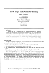
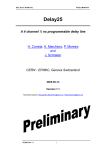
Figure 1.1: The AD readout thread (Thread 1) and the image aquisition thread (Thread 2),
scheduled with cooperative multi-threading
Figure 1.1 shows the execution flow for a system running these two threads. The image processing thread takes a long time for processing the image and the A/D readout thread can only
work for a short while until it gives up the CPU again. This is probably not the way it was
intended by the programmer of the first thread.
This problem could be “fixed” in several ways. One simple alternative would be to change the
second thread in a way that it calls the scheduler more often.
Listing 1.4: “friendly” image acquisition
#define IMAGESIZE=640*480
void image_processing_thread(){
int i;
char* ImageBuffer;
if !(ImageBuffer=malloc(IMAGESIZE))
return (-1);
init_camera();
while(1)
{
/* read image from camera... */
while (!CamReady()) KERN_schedule();
for (i=0;i<IMAGESIZE;i++)
{
ImageBuffer[i]=ReadCamByte();
KERN_schedule();
}
CHAPTER 1. AUTONOMOUS SYSTEMS
18
ProcessImage(ImageBuffer);
KERN_schedule();
}
}
However, the scheduler would waste a lot of CPU time being called that often. Moreover, the
changes would have to be made inside the ProcessImage() function too.
A tradeoff would be to call the scheduler only after some instructions, e.g. after every 100
processed pixels. But that would not be sufficient in all cases, since the processing time for 100
pixels is not known and therefore, no timing could be assumed for the complete system.
Preemptive multi-threading
The clean solution to the problem is a preemptive scheduler. Unlike the cooperative scheduler,
it is called by a timer interrupt, without any direct intervention of the thread. The runtime after
which the current thread is interrupted and control is given to the scheduler is called the time
quantum. The scheduler then decides if control is passed back to the current thread or to a
different thread. (Note that direct intervention by calling the scheduler is still possible.)
The preemptive scheduler can interrupt the thread at every point in its execution flow (unless
the thread takes explicit measures against it). Considering the last example, this resolves the
problem of the long runtime of the second thread. However, the scheduler will also interrupt
the first thread, lengthening the time between the readout of the A/D converter and the data
transmission. One possibility to avoid this is to switch off the scheduler during this time.
Listing 1.5: preemptive data acquisition
#define BUFSIZE=1024
#define READ_TIMEOUT=1000 /* milliseconds */
void data_acquisition_thread(){
int ad[4];
int i;
char DataBuffer[BUFSIZE];
int lasttime,lastticks;
int nowtime,nowticks;
lasttime=0;
lastticks=0;
while(1)
{
disable_preemption();
/* gather some data... */
read_clock(&lasttime,&lastticks);
for (i=0;i<4;i++)
ad[i]=I2C_ReadAnalogIn(1,i);
/* Form a data packet */
1.3. OPERATING SYSTEM SERVICES FOR AUTONOMOUS SYSTEMS
19
sprintf(DataBuffer,"----DATA PACKET----\n"
"AD1: %d\n"
"AD2: %d\n"
"AD3: %d\n"
"AD4: %d\n",ad[0],ad[1],ad[2],ad[3]);
/* send the data packet away */
RSM_send_frame(DataBuffer);
enable_preemption();
/* call the scheduler until READ_TIMEOUT is over */
do {
KERN_schedule();
read_clock(&nowtime,&nowticks);
} while (
deltatime(nowtime,nowticks,lasttime,lastticks)
<READ_TIMEOUT);
}
}
Once again, this is not an optimal solution since in this case, the scheduler is disabled during the
readout of the A/D converter. As shown already, this can take some time. With the scheduler
disabled, this time cannot be reused by another thread.
The alternative to this is to introduce priorities in the scheduler. By giving the data acquisition
thread a higher priority than the image processing thread, it will always “win” over the image
processing. Only while reading the A/D converter, the other thread will be run.
The next problem that arises is the implementation of the time delay. Since the data acquisition
thread has a higher priority and remains unsuspended, calling the scheduler does not give up
the CPU. The only solution for the thread here would be to lower its own priority while doing
the time wait so that the other thread can be started. Lowering it below the priority of the
other thread would lead to another problem since it would then be impossible to regain the
CPU to increase the priority again after the timeout expires. If both threads would have the
same priority, this would lead to the undesirable situation where only a part of the CPU time is
available to the image processing thread while the rest is wasted on polling the timeout.
A clean solution to this is to enhance the scheduler with an additional function which disables
a thread for a certain time.
Listing 1.6: scheduler-controlled KERN sleep()
#define BUFSIZE=1024
#define READ_TIMEOUT=1000 /* milliseconds */
void data_acquisition_thread(){
int ad[4];
int i;
char DataBuffer[BUFSIZE];
int lasttime,lastticks;
int nowtime,nowticks;
CHAPTER 1. AUTONOMOUS SYSTEMS
20
lasttime=0;
lastticks=0;
while(1)
{
/* gather some data... */
for (i=0;i<4;i++)
ad[i]=I2C_ReadAnalogIn(1,i);
/* Form a data packet */
sprintf(DataBuffer,"----DATA PACKET----\n"
"AD1: %d\n"
"AD2: %d\n"
"AD3: %d\n"
"AD4: %d\n",ad[0],ad[1],ad[2],ad[3]);
/* send the data packet away */
RSM_send_frame(DataBuffer);
KERN_sleep_ms(READ_TIMEOUT);
}
}
In this case, the A/D thread keeps its higher priority but is still suspended by the explicit
KERN sleep ms() call.
1.3.2 Scheduling repetitive tasks
Repeated execution of simple control tasks (SCT) play an important role in most autonomous
systems.
One typical example is motion control, which often makes use of some form of controller,
e.g. PID-controllers[KD97]. Control theory assumes that these controllers are implemented
continuously, i.e. with analog electronic components such as feedback amplifiers. However,
today they are mostly implemented digitally as a repetitive task on a micro-controller.
Another example for these simple tasks can be the behaviors of reactive robotic architectures
(see 1.1.3) and the layers of hierarchic robotic architectures (see 1.1.3).
What exactly is a SCT?
• A SCT has to be short in runtime. Usually, it has the structure of reading sensor values,
executing some simple computations on these values and storing the result.
• A SCT does not block, i.e. it does not wait an unbounded period of time for external
events. 2
• When executed, a SCT runs to completion and exits.
2
For data acquisition,a SCT might wait, but this blocking usually is bounded to a very short time.
1.3. OPERATING SYSTEM SERVICES FOR AUTONOMOUS SYSTEMS
21
When multiple SCTs are present in a system, they often are executed in very different time
intervals. One SCT monitoring ambient temperature may run once every few minutes where
an SCT for motion control may run 1000 times a second.
Implementing SCTs within a system seems straightforward. For example, by making use of
the preemptive scheduler, it is possible to schedule multiple SCTs in the following way. In this
example, the SCTs are hidden within the SCT xxx() functions.
Listing 1.7: repetitive threads
void thread_1a(){
while(1)
{
SCT_do_something();
KERN_sleep_ms(1000);
}
}
void thread_1b(){
while(1)
{
SCT_do_something_too();
KERN_sleep_ms(1000);
}
}
void thread_2(){
while(1)
{
SCT_do_something_else();
KERN_sleep_ms(500);
}
}
void thread_3(){
while(1)
{
SCT_do_something_fast();
KERN_sleep_ms(250);
}
}
The preemptive scheduler would execute these threads in the following sequence, provided that
there would be no interruption through preemption:3
3
Since the SCTs are short in runtime, it can be assumed that their execution is over before the time quantum for
the current thread expires.
CHAPTER 1. AUTONOMOUS SYSTEMS
22
Time
0 ms
250 ms
500 ms
750 ms
1000 ms
→
T1a
T3
T2
T3
T1a
T1b
T2
T3
T2
T3
T3
T1b
And this scheme would be repeated over and over again.
With the given example, the repetitive execution of the tasks is not exactly as intended since the
execution period is the sum of the execution time of the task and the wait time. To overcome
this problem, two separate thread can be used to schedule each task, a control thread that does
the scheduling and a worker thread that does the actual execution, as shown in the next example.
Listing 1.8: control thread and worker thread
void thread_1a_control(){
while(1)
{
KERN_wakeup(pid_of_worker_thread);
KERN_sleep_ms(10);
}
}
void thread_1a_worker(){
while(1)
{
KERN_suspend(getpid());
do_something();
}
}
As long as the CPU load is low, that means that the execution times are small compared to
the wait times, this execution scheme is fine, but it can contain times where a high number of
threads are to be executed where at other times, there are only few. For example, the previous
example contains a high number of threads that are to be executed at 0 ms, and few at 250 and
750 ms.
However, if the delay times between two executions of a thread are the only specification, a
scheme like the following would be more attractive:
Time
0 ms
250 ms
500 ms
750 ms
1000 ms
→
T3
T3
T3
T3
T3
T1a
T2
T1b
T2
T1a
1.3. OPERATING SYSTEM SERVICES FOR AUTONOMOUS SYSTEMS
23
Here, the time delays are the same, but the threads are more evenly distributed. This means
that this schedule can still be executed ’on time’ even if the wait times are significantly lower.
Moreover, implementing control and worker threads for every SCT is not very convenient and
it also uses many resources of the system, e.g. the the process table of the preemptive scheduler.
It is preferable to have an operating system service that handles SCTs and computes a schedule
for their execution based on the specification of periods.
Parts of the following section have already been published in the SAB 2000 proceedings supplement book[BKS00], in the ICRA 2001 [BK01a] proceedings and in the SIRS 2000 [BK00]
proceedings.
Here, a novel scheduling algorithm, the so-called B-scheduling4 , is presented which handles
SCTs running on different time-scales represented through so-called exponential effect priorities. Instead of directly specifying delay times in a linear way, an exponential scheme is used to
specify them. Therefore, so-called exponential effect priorities are introduced here. The idea
is that for each increase in a priority value by one, the execution frequency is halved.
In the remainder of this section the following naming conventions are used: the set of SCTs:
S= {s0 , ..., sN −1 }, the priority-value of a SCT si : pv[si ], the set of SCTs with priority k
or the k-th priority class: P Ck , and the highest used priority-value: maxpv. The definition
of a priority-value pv[si ] of SCT si within exponential effect priorities is that between two
consecutive executions of any SCT u ∈ P Cpv , every SCTs in P Cpv−1 is executed exactly
twice.
For solving the task of finding a suitable order of execution of the SCTs, a cyclic executive
scheduling approach[BW97] is used. This means there is a so-called major cycle, which is
constantly repeated. The major cycle consists of several minor cycles. Each minor cycle is a
set of SCTs which are executed in a fixed order when the minor cycle is executed. Every SCT
can be executed at most once per minor cycle, so the minor cycle can be a set. However, it is
still assumed that the SCTs in a minor cycle are executed every time in a fixed sequence.
To illustrate the problems involved in scheduling, Figure 1.2 shows a simple algorithm, which
schedules behaviors based on their priorities. The example shows the execution of one major
cycle, the repetitive execution of the major cycles is omitted. The outer loop counts the minor
cycles in round. The SCTs of priority-class P Ck are executed if round is a multiple of 2k .
This scheduler produces a similar result as the repetitive scheduling which makes use of the
preemptive scheduler in Listing 1.7.
This scheduler is correct since it produces a valid exponential effect schedule. The outer loop
counts the minor cycles. The execution of the SCTs of a process class pv in round i is determined by the expression i modulo 2pv becoming zero. This expression actually truncates the
most significant bits of i to zero so that only the bits bpv−1 · · · b0 are passed on. For the process
class pv − 1, the bits bpv−2 · · · b0 are truncated. This means that by continuously incrementing i, for every time bpv−1 · · · b0 becomes 0, bpv−2 · · · b0 becomes 0 twice. The first time it
4
B stands for behavior since it has first been used in the context of scheduling behaviors in reactive robotics
CHAPTER 1. AUTONOMOUS SYSTEMS
24
1
2
3
4
5
6
7
8
9
/* Execute the Major Cycle */
for(round = 0; round < nmic ; round = round + 1) {
/* Execute the Minor Cycle */
foreach sid ∈ S: {
if(round modulo 2pv[si ] == 0) {
execute sid
}
}
}
Figure 1.2: A simple scheduler S1 .
major cycle
s0.1 s0.1 s1.1
minor
cycle
s0.1 s0.1 s1.1
fixed
distance (1)
s0.1
1x
SCT with pv = 0
s1.i
nx
SCT with pv = 1
s1.n
minor
cycle
s1.n s0.1 s0.1 s1.1
unlimited
distance (n+1)
s1.n
low
balance
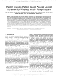
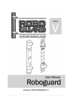
Figure 1.3: The simple scheduler S1 leads to a so-called unbalanced execution. One minor
cycle can consist of a single SCT s0.1 while a second minor cycle contains unlimited many
other SCTs. Hence, the execution of s0.1 is not evenly spread.
1.3. OPERATING SYSTEM SERVICES FOR AUTONOMOUS SYSTEMS
major cycle
s0.1
s0.1 s1.1
minor cycle
s1.n
minor cycle
1x
SCT with pv = 0
s1.i
nx
SCT with pv = 1
idle
time
unlimited idleness
unlimited (n)
s0.1
s0.1
25
s0.1 s1.1
s1.n s0.1
s0.1 s1.1
s1.n
balanced
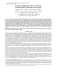
Figure 1.4: Adding idle time to balance the schedule made by S1 can lead to an unlimited waste
of time.
becomes zero is when bpv−1 · · · b0 is zero. The second time is when:
bpv−1 · · · b0 = 1 |0 ·{z
· · 0}
pv−1···0
The major problem with this algorithm is illustrated in Figure 1.3. Assume there is a SCT s0.1
with priority 0 and n SCTs s1.i with priority 1. So, #P C0 = 1 and #P C1 = n. The first
minor cycle consists of s0.1. As S1 executes all SCTs of a priority-class together, the second
minor cycle includes all SCTs with priority 0 and priority 1, i.e., this minor cycle has n + 1
SCTs. From a naive viewpoint, it can be said that the SCTs are badly distributed.
In a more formal approach, the so-called balance of a schedule S is defined as
balance(S) = min
min dist(si , x)
max dist(si , y)
where x and y are minor cycles and dist(si , z) is the number of SCTs which are executed
between start of the execution of si in cycle z and its next execution in cycle z + 2pv[si ] . If
the balance is one, then the schedule manages an equidistant spreading of every SCT over the
cycles. If the balances is close to zero than there is at least one SCT which is very unevenly
executed.
A small balance is undesirable. As illustrated in the above example, a SCT with low priorityvalue, i.e., a SCT which should be executed very often, has to wait for an unbounded timeperiod. This is also expressed by the balance of S1 which is in this case:
balance(S1 ) =
1
= 0 for n → ∞
n
CHAPTER 1. AUTONOMOUS SYSTEMS
26
The balance of S1 can be improved by adding idle time as illustrated in Figure 1.4. This way,
the balance can always be tuned to reach the optimum of one. But this is bought at the cost
of an unlimited waste of time. The idleness as the sum of idle-times in a major cycle is now
unbounded.
In general, a schedule S is time-optimal if and only if the idleness is zero.
1
2
3
4
5
6
7
8
9
10
11
12
13
14
15
16
17
/* Initialization */
/* computing the initial wait-values for each SCT sid */
quicksort(P)
pc = 1
start = 0
nslots = 1
for(i = 0; i < maxpv; i + +) {
start = 2 · start
nslots = 2 · nslots
∀id with pv[sid ] = pc : {
wait[sid ] =
reverse((start + id) modulo nslots )
}
start =
(start + #{sid | pv[sid ] = pc}) modulo nslots
pc = pc + 1
}
Figure 1.5: The initialization of B-scheduling.
The workload W L within a major cycle can be computed as the sum of the occurrences of each
SCT, i.e.
WL =
X
#P Ci · 2maxpv−i
0≤i≤maxpv
The number nmic of minor cycles per major cycle is determined by the highest priority value
maxpv as the SCT or the SCTs with this priority have to be executed once per major cycle. It
follows that the average number av of SCTs per minor cycle has to be
av = W L / nmic with nmic = 2maxpv
1.3. OPERATING SYSTEM SERVICES FOR AUTONOMOUS SYSTEMS
1 /* Execute the Major Cycle */
2 for(round = 0; round < nmic ; round = round + 1) {
3
/* Execute the Minor Cycle */
4
id = 0
5
done = 0
6
while( (done < perf ect) ∧ (id < #P) ) {
7
if(wait[sid ] == 0) {
8
execute sid
9
wait[sid ] = 2pv[sid ]
10
done = done + 1
11
}
12
id = id + 1
13
}
14
∀sid ∈ P : if(wait[sid ] > 0) : wait[sid ] = wait[si ] −
1
15 }
Figure 1.6: The execution of a B-schedule.
27
CHAPTER 1. AUTONOMOUS SYSTEMS
28
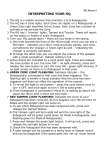
Slots
2pv
Layers
Flow of
execution
“empty” slot
“filled” slot
Figure 1.7: Slots and Layers of a SCT schedule
For an even distribution of the workload, the actual number of SCTs in a minor cycle has to be
equal to the average number av. Unfortunately, av is not necessarily an integer. Therefore, a
distinction between
perfect = dave and dirty = bavc
must be made.
A so-called perfect minor cycle has perfectly many SCTs, whereas the number of SCTs in a
dirty minor cycle accordingly is dirty. A bad minor cycle includes more than perfect or less
than dirty many SCTs.
The sequence in which the SCTs are executed within the minor cycles defines a number of
“Layers”. A SCT in the ith layer of a minor cycle is executed as the ith SCT when that minor
cycle is executed. This is shown in Figure 1.7.
B-scheduling computes a schedule SB such that
1. SB is time-optimal
2. SB is a exponential effect schedule
3. A SCTs is in the same layer of all minor cycles in which it is executed.
4. the SCTs are distributed over the cycles so that si is executed in cycle c + 2pv[si ] if and
only if si is executed in cycle c
5. the major cycle consists only of perfect and dirty minor cycles
It follows from properties 2,3 and 4 that S is well balanced as
dirty + 1
perf ect + 1
= 1 for av → ∞
balance (SB ) =
(1.1)
(1.2)
1.3. OPERATING SYSTEM SERVICES FOR AUTONOMOUS SYSTEMS
29
The worst-case balance of SB is 1/2 when only two SCTs are used and one is more frequent
than the other. In general, the balance becomes better the more workload is handled in each
minor cycle.
What is the difference between this and the simple scheduler and why is this one so much better
in terms of balance?
The simple scheduler executes all SCTs of a priority class pv in the minor cycle i where i
modulo 2pv becomes zero. Then, in the following 2pv − 1 minor cycles, no SCT of this class
is executed. The B-Scheduler evenly distributes the elements of the priority class pv over the
available 2pv minor cycles. For the priority class P C0 , this is easy since every element of P C0
is executed in every minor cycle. If there would be no SCTs in a higher priority class, the
length of the major cycle would also be one.
In this case, there is exactly one possibility to add the SCT into a minor cycle. Therefore, the
number of “slots”, i.e. the number of possible minor cycles to add a SCT to is one, although
the number of minor cycles in the final schedule might be higher. For the next priority class
P C1 there are two slots, for priority class P Ci there are 2i slots. Figure 1.7 shows a schedule
with eight slots of which six already contain two SCTs and two contain only one.
Whenever the number of processes in a priority class is a multiple of 2pv , the way in which the
members are distributed over the 2pv available “slots” is irrelevant. This is the case since all
minor cycles into which a SCT is “inserted” have the same number of SCTs after processing
all SCTs of P Cpv . In detail, if the priority class pv has k2pv members, these are distributed by
the algorithm into k “layers” because each minor cycle gains k new SCTs.
A problem arises if there is a remainder of empty slots after the insertion of priority class P Cpv
(which is assumed to be the lowest process class where there is such a reminder). This occurs
if #P Cpv modulo 2pv 6= 0, consequently, there are 2pv − (#P Cpv modulo 2pv ) empty “slots”.
To illustrate the connection with the perfect and dirty values defined before, if there would
be no further SCTs to insert, there would be 2pv − (#P Cpv modulo 2pv ) dirty and #P Cpv
modulo 2pv perfect minor cycles. To be able to fill these empty slots in the dirty cycles by
inserting processes of the next process class P Cpv+1 before inserting a SCT into one of the
perfect cycles (and thus forming a bad cycle), the location of the left-over dirty cycles (now
called empty slots) must be known.
In terms of the original 2pv slots this is easy, the slots just have to be numbered. By maintaining
a pointer to the next available empty slot, all empty slots can be found. If this pointer is to be
used to identify the 2pv+1 available slots in the next-higher process class, a problem arises. An
operation has to be applied to the pointer to convert it from a pointer for process class pv to a
pointer for process class pv + 1 so that:
1. for every empty slot in process class pv there are two empty slots in process class pv + 1
2. and the new value of the pointer identifies all empty process slots for process class pv + 1
if its old value did identify all empty slots for the process class pv.
CHAPTER 1. AUTONOMOUS SYSTEMS
30
Obviously, this problem can be solved by maintaining a data structure that is used to remember
all currently empty slots. When process class pv is processed, all empty slots that are still
available from process class pv − 1 are replaced by two slots. If the original slot was in minor
cycle i of process class pv − 1, then it is replaced by a slot in minor cycle i of process class pv
and a slot in minor cycle i + 2pv−1 . This approach is illustrated in Figure 1.8.
2pv-1
pv-1
2pv
pv
Figure 1.8: Empty slots that are generated from the transition pv − 1 → pv
This problem can also be solved by the bit reverse function in line 12 of the program shown in
Figure 1.5 without any additional datastructure.
The bit reverse function for a n-bit-value is defined as
bitreverse(n, v) =
n−1
X
2i bittest(v, n − i)
(1.3)
i=0
where bittest(v, i) tests if the 2i bit in v is set.
Or simpler, if v = bn · · · b0 , then bitreverse(n, v) = b0 · · · bn .
As it can be seen in Figure 1.8, the distance of the two slots that replace one slot of the previous
pv − 1 major cycle is 2pv−1 . That is exactly the value of the most significant bit of the index
value i that can address all minor cycles in the current major cycle. By applying bitreverse(i),
this bit is flipped in the result value whenever i is incremented by one. Therefore, the two slots
created can be addressed with bitreverse(pv, i) and bitreverse(pv, i + 1) if i is a multiple of 2.
Moreover, if the first empty slot in priority class pv−1 is bitreverse(pv−1, i), then the two first
empty slots for priority class pv can be found at bitreverse(pv, 2i) and bitreverse(pv, 2i + 1).
This approach is illustrated in Figure 1.9.
In this figure, the numbers in the squares representing the SCTs illustrate the sequence in which
the SCTs are inserted. This sequence is generated by the bitreverse() function. As an example,
the sequence in which the slots for pv = 3 are filled is :
1.3. OPERATING SYSTEM SERVICES FOR AUTONOMOUS SYSTEMS
31
slot number: 0 1 2 3 4 5 6 7 8 9 10 11 12 13 14 15
2pv-1
pv-1
1 5 3 7 2 6 4 8
1 5 3 7 2 6 4 8
2pv
pv
1 9 5 13 3 11 7 15 2 10 6 14 4 12 8 16
1 9 5 13 3 11 7 15 2 10 6 14 4 12 8 16
Figure 1.9: using the bitreverse function to fill empty slots
Sequence number
1
2
3
4
5
6
7
8
index
0
1
2
3
4
5
6
7
bitreverse(pv, index)
0
4
2
6
1
5
3
7
Now that the bitreverse function can be used to identify left-over slots from the insertion of
the last priority class, the algorithm can fill the SCTs into minor cycles so that only dirty and
perfect minor cycles are generated.
This is the case since before any SCT is added to a perfect cycle, all dirty cycles are filled first
(and thus made perfect). After this, according to the definition of perfect and dirty cycles, the
workload is evenly distributed over all minor cycles and dirty = perfect = av = W L / nmic .
When the next SCT is inserted, W L is incremented by one, therefore, perfect is incremented
as well and the schedule contains one perfect minor cycle and nmic − 1 dirty ones.
1.3.3 Inter-thread communication and synchronization
If there are multiple threads in the system, they often have to exchange data. When using a
preemptive scheduler, the time at which execution of one thread is stopped and the execution
of another task is resumed is not known a priori.
32
CHAPTER 1. AUTONOMOUS SYSTEMS
The C programming language’s global variables are accessible for all parts of a program since
they belong to the global name-space. Since all threads are also part of this global namespace,
this opens up a trivial possibility for inter-thread communication.
Listing 1.9: trivial inter-thread communication
int global_variable;
void thread_1()
{
while(1){
global_variable=read_sensor();
KERN_sleep_ms(1000);
}
}
void thread_2()
{
while(1){
compute_target(global_variable);
drive_to_target();
}
}
These two threads may communicate with different results. Depending on the execution times
of the called functions, Thread 1 might be interrupted before the global variable is written and
thread 2 might work on old data. However, this might still be acceptable, but the outcome of
the program might be not transparent.
Whenever the result of a computation depends on the sequence in which instructions are executed in different threads, such a situation is called a race condition. Considering the next
example, there are cases where a race condition leads to problems that cannot occur in a program with only one thread:
Listing 1.10: bad example of inter-thread communication
void thread2()
{
while(1){
if (global_variable<=0){
drive_to_target();
compute_target(global_variable);
}
if (global_variable>0) emergency_stop();
}
}
In the previous listing, consider a change of global variable by a different thread between
line 4 and line 8, e.g. from a positive to a negative value. In this case, no if condition is true
1.3. OPERATING SYSTEM SERVICES FOR AUTONOMOUS SYSTEMS
33
and none of the functions is called. This could never happen in a linear program but is possible
in a multithreaded system.
Once again, an obvious solution is to prevent any other access to global variable while
reading or writing it. Disabling the preemptive scheduler is an option. By this, the read operation becomes atomic,i.e. it cannot be interrupted by any other operation 5 . Similar problems
can always arise if global data is passed between threads and can become inconsistent. The
parts of a program where such inconsistencies can arise are called critical sections.
1.3.4 Mutexes, spin-locks and semaphores
The classical solution to the problem presented in the last section is to enforce mutual exclusion,
that is to block one thread before entering the critical section while the other thread is still
executing code within the critical section. Unfortunately, the C language does not contain a
language construct that provides mutual exclusions, a so-called mutex. We therefore have to
find an alternative implementation as a function of the operating system.
A simple solution is to introduce a global variable counting the number of threads entering the
critical section as shown in Listing 1.11.
Listing 1.11: Mutual exclusion by counting
void thread_1()
{
while(1){
counter--;while(counter<0);
global_variable=read_sensor();
counter++;
KERN_sleep_ms(1000);
}
}
void thread_2()
{
while(1){
counter--;while(counter<0);
if (global_variable<=0){
compute_target(global_variable);
drive_to_target();
}
if (global_variable>0) emergency_stop();
counter++;
}
}
5
An alternative atomic read operation would be to evaluate global variable in one single instruction or
copying it into a local buffer before evaluation. But although possible in this case, the approach fails for complex
data-structures that cannot be handled in one CPU instruction.
CHAPTER 1. AUTONOMOUS SYSTEMS
34
However, this can still lead to a deadlock situation: If the first thread decrements the counter and
is then preempted, the second thread also decrements the counter and compares it afterwards,
both threads cannot continue since the counter is at -1 now.
One possible solution without operating system intervention is that each thread writes a unique
number instead of decrementing the counter. By this, the thread entering the mutex can check
whether it properly entered the mutex. If not, it goes back to wait. This is illustrated in Listing
1.12.
void thread_1()
{
while(1){
Listing 1.12: Mutual exclusion with unique IDs
do {
while(lock);
lock=1;
} while (lock!=1);
global_variable=read_sensor();
lock=0;
KERN_sleep_ms(1000);
}
}
void thread_2()
{
while(1){
do {
while(lock);
lock=2;
} while (lock!=2);
if (global_variable<=0){
compute_target(global_variable);
drive_to_target();
}
if (global_variable>0) emergency_stop();
lock=0;
}
}
Finding unique IDs is simple, one could use the thread IDs of the operating system. But the wait
for a free mutex is executed in form of a spin-lock, i.e. a repeated polling of a memory location,
so at least the rest of the thread’s quantum is wasted by useless polling of the unchanged
1.3. OPERATING SYSTEM SERVICES FOR AUTONOMOUS SYSTEMS
35
variable. Again, it is better to leave this operation to the operating system by introducing a new
operating system function.
The two functions necessary are the following:
• mutex enter(MUTEX mutex) checks if another thread has already entered the mutex section and prevents other threads from entering.
• mutex leave(MUTEX mutex) frees the mutex section again so that other threads
can enter it.
Their use is demonstrated in Listing 1.13
MUTEX the_mutex;
Listing 1.13: operating system mutex
void thread_1()
{
while(1){
mutex_enter(the_mutex);
global_variable=read_sensor();
mutex_leave(the_mutex);
KERN_sleep_ms(1000);
}
}
void thread_2()
{
while(1){
mutex_enter(the_mutex);
if (global_variable<=0){
compute_target(global_variable);
drive_to_target();
}
if (global_variable>0) emergency_stop();
mutex_leave(the_mutex);
}
}
However, in some situations, it is inevitable to use the original approach to block interrupts,
e.g. when manipulating data structures of the operating system itself to implement operating
system mutexes. But the blocking should be used as rarely as possible and only for a few
instructions.
A construct that is closely related to mutexes is a semaphore. Two operations can be applied to
a semaphore, up and down. These are generalization of the increment and decrement operations
on the counter in Listing 1.11. Instead of waiting in a spinlock, the operating system will put the
CHAPTER 1. AUTONOMOUS SYSTEMS
36
Time
Thread H
Thread L
T1
T2
T3 T4 T5 T6
Figure 1.10: direct blocking priority inversion with two threads
decrementing thread into suspended state when the semaphore counter is zero. When another
thread calls the incrementing operation, the operating system will wake up one of the threads
that have been suspended.
Semaphores have the advantage that they can also protect a section so that only a limited
number of threads can make use of a certain resource. The classic example is a system with a
number of printers. As long as there are still printers available, a thread can enter the printer
driver function by decrementing a semaphore. As soon as there are no free printers left, all
other threads are blocked from using a printer. When a currently used printer is released by the
thread using it by incrementing the printer semaphore, one of the waiting threads is unblocked
and the printer can be used by it.
1.3.5 Priority inversion
One specific problem arises if kernel level semaphores and mutexes is combined with a preemptive priority-based scheduler: the so-called priority inversion problem. Priority inversions
occur whenever a low priority thread enters a mutex that a higher priority thread wants to enter
as well. Since the higher priority thread blocks until the mutex is available again, although
having higher priority it cannot run.
In Figure 1.10 this situation is illustrated. Thread H is the higher priority thread, thread L is
the lower priority thread. At time step T1, the higher priority thread is entering the mutex
section, at time step T2, the lower priority thread is entering the same mutex section. At time
step T3, the lower priority thread is entering the mutex section again. At time step T4, its time
quantum is over and it is therefore preempted by the higher priority thread. As soon as the
higher priority thread also tries to enter the mutex section, it is blocked (T5) and control is
passed back to the lower priority thread until it leaves the mutex section (T6). This situation
is called direct blocking. It cannot be prevented in general and can only be avoided by careful
system design, i.e. by leaving mutex sections as quickly as possible again.
But the problem gets even worse if the low priority thread is preempted by a medium priority
1.3. OPERATING SYSTEM SERVICES FOR AUTONOMOUS SYSTEMS
37
Time
Thread H
Thread M
Thread L
T1 T2 T3
T4 T5
Figure 1.11: indirect blocking priority inversion with three threads
Time
Thread H
Thread M
Thread L
T1 T2 T3 T4 T5
Figure 1.12: Priority inversion with three threads
thread as in time step T3 in figure 1.11. Such a situation as shown in figure 1.11 is called
indirect blocking. The medium priority thread can block the higher priority thread by blocking
the lower priority thread that entered the mutex. This situation can be present for extended time
periods, even if the programmer of the low priority thread tried to give back the resource as
soon as possible. The medium priority thread cannot prevent the situation directly, since it is
not using any mutex operation at all. It is only resolved here after the medium priority thread
gives up the CPU at time step T4. Then, the low priority thread can continue and leave the
mutex section. After that, it is preempted by the high priority thread.
One solution is to prevent preemption while in a mutex. But this has drawbacks since it blocks
other threads from the CPU while any thread is in any mutex section. A better solution here
is the so-called priority inheritance. While a lower priority thread is in a mutex section that a
higher priority thread is trying to enter, its priority is increased to the priority of the highest
thread trying to enter the mutex section. This situation is illustrated in figure 1.12. Although
the medium priority thread becomes ready at time step T3, the low priority thread continues to
run since it inherited the higher priority in time step T2. After it leaves the mutex at time step
CHAPTER 1. AUTONOMOUS SYSTEMS
38
T4, the higher priority thread takes over. Only after this thread gives up the CPU at time step
T5, the medium priority thread continues.
1.3.6 direct hardware access
As stated in section 1, one key component of an autonomous system is that it’s connected to
the world by the means of sensors and actuators. Usually, an autonomous system not only has
several sensors and actuators but also multiple sensors and actuators of the same type. These
devices are connected to the system with various busses, ports and networks. The access to
these devices is either provided through some kind of driver (e.g. for I2C devices) or through
direct access of memory locations associated with a device, i.e. a memory mapping of the
device’s registers. The readout of an I2C-connected A/D converter is given here as an example.
#define
#define
#define
/*
Listing 1.14: reading an A/D device through the I2C driver
AD_ADDRESS 0x92
AD_CHANNEL 1 /* 0..3 */
AD_CONFIG 0
Configuration= 4 single-ended a/d inputs */
char analog_mbuf[MAXI2CMESSLENGTH];
struct i2cmess analog_m;
int main()
{
/* I2C a/d */
I2C_init (I2CA, I2CA_BASE);
analog_m.address = AD_ADDRESS;
analog_m.nrBytes = 1;
analog_m.buf = analog_mbuf;
analog_mbuf[0] = AD_CONFIG;
I2C_process (I2CA, I2C_MASTER, &analog_m);
/* set channel */
analog_m.address = AD_ADDRESS;
analog_m.nrBytes = 1;
analog_m.buf = analog_mbuf;
analog_mbuf[0] = (AD_CONFIG & 0x70) | (AD_CHAN & 0x03);
I2C_process (I2CA, I2C_MASTER, &analog_m);
/* read value */
analog_m.address = ad_data[chip].address | 0x1;
/* Read address */
analog_m.nrBytes = 2;
/* Read one false byte, then read value */
analog_mbuf[0] = 0; /* clear buffer */
analog_mbuf[1] = 0;
analog_m.buf = analog_mbuf;
1.3. OPERATING SYSTEM SERVICES FOR AUTONOMOUS SYSTEMS
39
I2C_process (I2CA, I2C_MASTER, &analog_m);
/* now the result is in analog_mbuf[1] */
printf("result = %d",analog_mbuf[1]);
}
This code is complicated, highly hardware-dependent and unportable.
Listing 1.15: reading an A/D device through an interface component
int main()
{
I2C_init (I2CA, I2CA_BASE);
I2C_init_analog();
printf("result = %d",I2C_ReadAnalogIn(1,1));
}
This code is easily portable since all access to the hardware is hidden in component interface
functions. However, it is still hardware-dependent since the electrical interface between the
control hardware is left to the designer of the autonomous system and is therefore still visible
in the application code in the sense that it is the first AD channel of the first AD chip. Moreover,
the code is much simpler, so even without prior knowledge of the underlying hardware, it is
easy to understand what is the purpose of the code.
A third property is hidden in the I2C init analog() function. It is automatically discovering all A/D interfaces present in the system and is presenting them in an abstract way,
independent of their connection to the system. This allows simple extension of the system by
adding more a/d chips and addressing them in a similar way.
1.3.7 realtime clock
The autonomous system interacts with the physical world. To be able to measure properties
of the world, a way to measure time is necessary. One simple example is a measurement of
the speed of a robot, in this case by observing pulses of a rotary encoder. The pulses are often
decoded by the hardware so the application program just has to wait a while and then read the
counter.
#define QD1 1
#define QD2 2
int main()
Listing 1.16: measuring speed (bad example)
40
CHAPTER 1. AUTONOMOUS SYSTEMS
{
short x;
int i;
TPU_init();
TPU_makeqd(QD1,QD2);
TPU_getqd(QD1); /* reset QD counter */
for (i=1;i<1000000;i++); /* wait some time */
x=TPU_getqd(QD1); /* read QD */
printf("x=%d\n",x);
}
In this example, hardware functions of the RoboCube are used to count the pulses. The
TPU getqd() function returns the number of pulses counted. Here it is assumed that the
quadrature decoder attached to a wheel axis records 64 signal edges for one full rotationon of
the quadrature encoder. It is further assumed that the wheel has a diameter of 5 cm, so the robot
moves π × 5cm = 15.7cm for each rotation of the wheel. From this, we can easily calculate
cm
the distance traveled to be d = 15.7
64 x.
Depending on the underlying architecture, the time between the two readouts can be calculated,
for the RoboCube, it will be roughly one second with no preemption and no other interruptions
taking place. With reading of x = 384 pulses, the robot would move at about 0.94 m
s . But as
we have seen in the previous examples, we cannot assume that the task was running uninterrupted. By assuming that a second thread of equal priority exists in the system and CPU time
is distributed equally between the two threads, executing the loop would roughly take twice
as long, the robot would therefore travel twice as fast even with the same amount of pulses
counted. This significant underestimation of the speed could lead to a dangerous situation.
Even if a operating system function would be used that suspends the thread for one second,
this situation cannot be avoided. The kernel function can only guarantee that the task will
sleep at least the specified time because after the suspend time is over, the process can still be
preempted by other tasks with higher priority. So, if the measurement time cannot be specified
exactly beforehand, it should be possible to measure it afterwards.
The realtime clock was implicitly introduced in Section 1.3.1 with the read clock() function. At that moment, the underlying mechanism for reading a clock was not explained. The
operating system can keep track of the time by using the same hardware timer that is used
for triggering the preemptive scheduler. Each time, the hardware timer triggers a hardware
interrupt, the internal operating system clock counter is incremented. This is called a “clock
tick”. Obviously, this scheme cannot measure times that are shorter than the rate with which
the hardware timer triggers the increment. On the other hand, the interrupt service routine for
the timer interrupt also uses CPU time, so calling it more often reduces the CPU time available
for the rest of the system. This tradeoff has to be decided from application to application.
The realtime clock is often represented as a number of counters since one counter does not have
sufficient bits to measure extended periods of time. To avoid inconsistent reads on these counts,
1.3. OPERATING SYSTEM SERVICES FOR AUTONOMOUS SYSTEMS
41
the read operation must be made atomic by disabling the timer interrupt during read operations.
Note that this does not lead to missed clock tick since the hardware holds unserviced interrupt
requests pending. So as long as the time between the disabling of the interrupt and the reenabling of the interrupt plus the execution time of the timer interrupt service routine does not
take longer as the interval between two clock ticks, no clock tick is missed. For example in the
standard configuration of CubeOS, timer ticks happen every 977µs. Since the 68332 CPU can
execute a new instruction about every four clock cycles, a CPU running at 16 Mhz clock speed
could execute 3908 CPU instructions before an interrupt would be lost.
Since the internal counters can only have a fixed length, the clock counters will overflow sooner
or later. CubeOS uses two 32-bit counters, one for fractions of seconds and a second one
to count seconds. The application program has to deal with this situation too, but since the
timespan for the overflow of an unsigned 32 bit second counter is 136 years, it will hardly
happen in the lifetime of a system.
Listing 1.17: measuring speed
#define QD1 1
#define QD2 2
int main()
{
short x;
int i;
struct timeval tp1;
struct timeval tp2;
TPU_init();
TPU_makeqd(QD1,QD2);
disable();
gettimeofday(&tp1,NULL);
TPU_getqd(QD1); /* reset QD counter */
enable();
KERN_ssleep(1) /* wait (at least) one second */
disable();
gettimeofday(&tp1,NULL);
x=TPU_getqd(QD1); /* read QD */
enable();
printf("x=%d t1=%f t2=%f\n",x,
(tp1.tv_sec+tp1.tv_usec/1000000),
(tp2.tv_sec+tp2.tv_usec/1000000));
}
42
CHAPTER 1. AUTONOMOUS SYSTEMS
1.3.8 initialization and configuration
Autonomous systems are build (and often re-build) in various configurations and therefore
require far more configuration information than e.g. a normal PC. If the software developed for
an autonomous system is only to be run on exactly this one system, then maintaining different
configuration is not an issue and the configuration can be easily maintained directly in the
code, as shown in the previous examples. But the operating system itself shall be usable over a
possibly wide range of different autonomous systems, so it needs support for the tailoring to a
special configuration from different configuration options.
Configurations can either be determined a priori or at runtime. If predetermined, it can be
defined statically so that it cannot be changed at runtime or dynamically so that later configuration changes are possible while the system is running. But depending on the nature of the
configuration information, it may not need to be changed later on.
Often, the configuration for autonomous systems can be structured in some classes, for which
some parts of the configuration are equal for all of them. An example would be a specific
computational core that would stay fixed but different sensors could be connected to it. There
should be a way to specify and re-use such configuration classes.
One example for configuration that is not likely to change are hardware configurations such as
interrupt levels, I/O memory locations or device addresses. Some of this information has to be
present at startup (such as the address of program and data memory) where as others can be
automatically detected during initialization. But during system operation, hardly any of this is
supposed to change. This is also a candidate for a hardware configuration class.
Configuration information which is likely to be changed over time is software configuration,
e.g. the parameters of the control software during system tuning. If configuration is changed
during runtime, there should be a way to store the current configuration persistently so that
in can be reused later on. But in most cases, the configuration data will simply be printed
out and manually set again or written to a configuration file. System Initialization is related
to configuration in the way that some configuration has to be known in order to initialize the
system where as other information is determined upon initialization.
Listing 1.18: initialization and configuration of an AD device
int main()
{
I2C_init (I2CA, I2CA_BASE);
I2C_init_analog();
}
In this example, the configuration for the I2 C controller chip is predetermined, e.g the base
address of the controller chip is given by the I2CA BASE macro. Other information, such as
which A/D devices are present in the system are determined by the I2C init analog()
function.
1.4. COMMUNICATION SERVICES FOR AUTONOMOUS SYSTEMS
43
The I2C init analog() function gives some console output for debugging. For a standard
RoboCube, this could look like the following:
analog
analog
analog
analog
analog
analog
device
device
device
device
device
device
0
1
2
3
4
5
at
at
at
at
at
at
address
address
address
address
address
address
0x90
0x92
0x94
0x96
0x98
0x9A
In this case, 6 analog devices with a total of 24 A/D inputs have been found.
1.4 Communication services for autonomous systems
An autonomous system is often used as a part of a larger setup of multiple autonomous systems
that need to communicate.
Communication systems for mobile autonomous systems have some unique properties:
• wireless: mobile autonomous systems can rarely establish a wired connection with cables.
• ad-hoc: An autonomous system often cannot rely on a pre-established communication infrastructure, so two systems should be able to communicate without an explicit communication infrastructure like base station transmitters etc. Moreover, autonomous systems
should be able to detect other communication partners without explicit configuration.
• robust: Since the environment of the communication often cannot be predetermined, the
communication system should be robust against interference both from natural sources
and from other systems present in the environment.
• multi-party: The communication between autonomous systems is often not only between two partners. Therefore, other forms of communication like multicast or broadcast
should be available as well.
• The resources of the autonomous systems are bound with respect to energy, the communication system should reflect that.
From the many available commercial communication systems, only few can fulfill these constraints. Therefore, the choice of a communication system has to be left to the user. Only
recently, new wireless communication system like Bluetooth[BT] are available. It has been
CHAPTER 1. AUTONOMOUS SYSTEMS
44
designed for networking battery-powered mobile devices, therefore it has the required properties for the use in mobile autonomous systems. Unfortunately, only few commercial products
are available at the moment. The standardization process for Bluetooth is still in progress
and therefore, it is not yet clear if Bluetooth will be a suitable communication method for
autonomous systems.
Within the communication service, the same constraints that apply for communication hardware also apply for the operating system communication support. Due to restricted hardware
resources, the services should be as efficient as possible.
There are multiple design guidelines for an efficient implementation of communication. A few
of them are listed here:
• Optimize energy usage: disable unused communication devices if they are not used.
Especially transmitters consume lots of energy.
• Instead of copying data, use pointers to data. Copying data from buffer to buffer should
be avoided whenever possible.
• Use datatypes that can efficiently be handled by the CPU, i.e. that fit the databus width
and can be analyzed with few instructions.
• Whenever possible, use hardware features to reduce CPU overhead. Many communication devices can handle address detection independently. This means that the CPU can
do other tasks instead of reading every communication only to determine that it is to be
discarded.
1.4.1 wireless communication
For wireless communication, sound, light or radio waves are commonly used transport medias.
Each of them has its specific advantages and drawbacks.
• Sound waves are easy to generate and can be sent out omni-directional. However,
bandwidth is limited by the physical properties of the emitters and receivers and the
frequency-dependent propagation of sound waves. Moreover, sound waves are prone to
interference and the achievable signal-to-noise ratio is limited.
• Light of various wavelength is also easy to generate and detect. Its wavelength can
be chosen such that interference is minimal, e.g. there are matched infrared transmitters
and receivers. The available bandwidth is very high, it is mostly limited by the frequency
response of the emitter and the receiver. However, light needs a path, either directly or
through reflections, between the emitter and the receiver, so it’s application is limited to
situations where the environment can be controlled. One popular communication system
based on infrared light is the IRDA protocol suite[MBD+ 98].
1.4. COMMUNICATION SERVICES FOR AUTONOMOUS SYSTEMS
45
• Radio waves need more complicated and therefore more expensive transmitter and receiver components. But apart from this, they are almost ideal for the use on autonomous
systems. They can be transmitted and received omni-directional, can communicate over
great distances with very limited power usage[QRP] and the available bandwidth is very
high. The limiting factor here is mostly the availability of off-the-shelf transceiver devices and regulatory compliance with the various international laws governing the transmission of radio waves.
1.4.2 modulation and data encoding
To transmit data over a wireless communication system, the data has to be converted to a form
that is suitable for transmission. All three communication systems mentioned above are linear
communication systems in the sense that they transmit discrete analog values. Depending
on the physical properties of the space between the transmitter and the receiver, these analog
values are changed in a more-or-less predictable way. The use of modulation leads to a change
of the properties of a carrier signal in such a way that these changes reflect the data to be
encoded. An important factor for the choice of a modulation scheme is that these changes are
not varied by the communication channel. One example is frequency shift keying, short FSK.
In this modulation system, a sine-wave carrier signal is modulated by changing its frequency
according to the digital modulation data. For a bit value of 0, a carrier signal of frequency
f is transmitted, for a bit value of 1, a carrier signal of frequency f + s is transmitted, f
and s being positive frequency values. A simple detector for this modulation are two tuned
resonance circuits for the frequencies f and f + s. Depending on which resonance circuit is in
resonance with the input signal, the detector outputs a digital 0 or 1. Even if the amplitude of
the sine carrier signal changed at the input of the detector, the frequency of the input signal is
invariant However, a certain minimal amplitude is necessary for the detection as, depending on
the rate of change of the digital signal, a minimal frequency shift s is necessary. For a detailed
introduction in various modulation schemes for digital communication, see [GG97].
Depending on the communication system and the transport medium, several statistical properties of the data stream have to be observed, e.g. the stream sometimes has to be balanced,
i.e. it’s number of bits with value 1 has to be as high as the number of bits with value
0. A simple scheme to ensure this property is “Manchester encoding” as it is used Ethernet
networks[IEE88].
1.4.3 Media Access Methods
When communication channels are shared between multiple parties, rules must be followed to
determine who is using a communication channel at a time. These rules can be very simple,
e.g. one party is allowed to transmit all the time. However, they must be chosen depending on
the application and the nature of the communication.
46
CHAPTER 1. AUTONOMOUS SYSTEMS
In complex communication systems, the media access rules are modeled after the same considerations as e.g. a scheduler in a general-purpose operating system is modeled, i.e. there are
goals, e.g. equal distribution of communication resources or delay time maximas. Therefore,
it is very hard to give an optimal media access algorithm for all applications.
However, there are some successful communication systems that can give guidance for forming a media access method. If communication is rarely taking up the full communication
bandwidth of a channel, a randomized method like CSMA/CD (Carrier Sense Multiple Access
/ Collision Detect)[Rag93] can be chosen. In this case, a party listens into the channel before
transmitting. (Carrier Sensing). In case that the communication channel is occupied by another
party, it waits for this communication to stop. Whenever the communication channel is free,
the party transmits, monitoring its own transmission (Collision Detect). When its own transmission is not the same as the one from the monitor, another party is transmitting as well, a
collision is said to have occurred. In this case, both parties stop their transmission and wait
a randomized time until they try to communicate again. Obviously, this media access method
has severe drawbacks if the communication channel is intensively used, then the probability for
waiting (and for collisions) is high. Another problem is that the time until one party is allowed
to transmit is not bound.
Another method for media access is token passing[Rag93]. One party is selected to “have the
token” in the beginning. This party is allowed to transmit. After it did transmit some or all
available data, it “passes” the “token” on to the next party by sending a specialized data packet,
the “token”. Then, this party is allowed to transmit. Depending on the way, the next party to
have the token is chosen, there are multiple implementations of token passing possible. One
problem with token passing is error recovery and startup. In the beginning, there must be a
special protocol to determine the first station to transmit, the “token” must be inserted into the
system. Due to communication errors, the “token” might also get lost, then the system has to
recover from this and recover the “token”.
Token passing has the advantage that as long as the token is present in the system, it can be
made to behave deterministically for timing and throughput, but if the token is lost, it needs
some recovery mechanisms.
Fortunately, in some applications of autonomous systems, much simpler media access methods
can be used. For example, the VUB AI Lab RoboCup team (See Section 4.4) uses a single
“master” station that is the only one transmitting.
In general, it can be said that the media access method has to be left to the application programmer because it is so dependent on the application of the system.
1.4.4 high-level data encoding
Another problem arises in the interaction of autonomous systems using various CPUs and
operating systems. In this case, the basic datatypes of the systems might not be the same.
1.5. CONCLUSION
47
For text encoding, the effects may be neglectable, but even binary data can be encoded differently. One example is the position of the four bytes of a 32-bit word in memory. If a 32-bit
word has to be send from a PC with an Intel CPU to a RoboCube with a Motorola CPU, as
four byte values, the two systems have to agree to a common standard on the byte ordering.
Similar problems arise for alignment6 and floating point encoding. There are various standards
that describe data encoding[Sun87, XML].
The operating system has to provide some mean to encode (and decode) data before sending it
to other systems.
1.5 Conclusion
An operating system has to support the following functions to be suitable for the use on autonomous systems:
• preemptive multithreading
• a service to schedule repetitive executions of simple tasks e.g. based on exponential
effect priorities
• basic interthread communication services such as mutexes and semaphores including a
priority inheritance mechanism
• functions to provide simplified access to sensors and actuators
• a realtime clock
• a communication service capable of supporting wireless communication between multiple systems
• and a service that tailors the operating system so that only effectively used services are
provided and the system is configured so that it runs on the hardware selected to build
the autonomous system on.
6
some CPUs can only work with 32 Bit values if they are properly positioned on a memory address that can be
divided by four
48
CHAPTER 1. AUTONOMOUS SYSTEMS
Chapter 2
Operating system design
In the last chapter, the functions were analyzed that an operating system for autonomous systems should support. In this chapter, different possible internal designs are presented and
analyzed. From these, one is selected to implement CubeOS.
2.1 Operating Systems
Operating systems literature presents a number of generalized operating system design goals
such as multiprogramming/-threading, fair resource sharing, inter-thread synchronization and
communication together with common problems associated with attaining these goals. Sharing
of resources is a well-researched problem, for a discussion of this topic, see [Tan87].
Operating system concepts can be put into several classes depending on their internal design.
The classes presented here are overlapping, so there are e.g object-oriented microkernel systems.
• Monolithic kernel operating systems are operating systems that consist of one static kernel that implements the whole application programming interface.
• Micro-kernel operating systems distribute their internal functions to a number of processes that communicate with each other via interprocess communication. This interprocess communication is the only function implemented by a minimal kernel. The API,
although implemented by different processes is presented to the application in a uniform
way (through the IPC interface of the micro kernel) as it is in the monolithic kernel.
• Nanokernels are application-specific operating systems which have only the purpose of
hosting exactly one application program, often a virtual machine such as the Java VM.
These kernels only implement exactly the API needed by their application. Nanokernels
are mostly monolithic, although micro-kernel implementations are possible.
49
CHAPTER 2. OPERATING SYSTEM DESIGN
50
• object-oriented operating systems are similar to micro-kernels, but do not present a uniformed API to the application. Instead, the application program uses an object-oriented
interface that can be extended through object-oriented techniques. An additional concept
in some object-oriented operating systems are concurrent objects[YTT89] that play the
same role as threads do in a micro-kernel operating system.
• component operating systems are also similar to micro-kernels. However, the operating
system kernel can be extended with additional (application-specific) components so that
the border between application programs and operating system becomes blurred.
• realtime operating systems are optimized for the use in realtime systems.
These different types of operating systems are discussed in the following sections with a special
focus on their suitedness for the use in autonomous systems.
2.1.1 Monolithic kernel operating systems
Application
Program
Application
Program
Application
Program
API
Kernel
Drivers
I/O Hardware
Figure 2.1: The structure of a monolithic kernel
The traditional way of implementing an operating system is to define an application programming interface and to program a kernel which implements it. The kernel itself is seen as one
big program that implements all the functions necessary to execute all API functions. Most
operating systems that are used today have been implemented in this way, the traditional UNIX
kernel is a good example, others are MacOS, Novell Netware and XINU[Com84].
Unix is also a good example for the way operating system design is guided by the intended
application software.
The UNIX API system calls are mainly centered around program execution and file-system
operations[Rit79]. The first part of UNIX that has been defined in its development process has
2.1. OPERATING SYSTEMS
51
been the file-system and its API, first on paper, later implemented on a PDP-7. At that time, the
file-system API was that important, because the computer system only had minimal RAM, so
most program data had to be kept on disk. The PDP-11 which was the second machine UNIX
was ported to had 24 kBytes of main memory of which 16 kBytes were allocated for the kernel
and 8 kBytes were available for user programs.
Although this seems small compared to computers used today, the performance impact from
the lack of memory was minimal. This was the case since while the CPU had a memory cycle
time1 of one microsecond and most instructions used two cycles, the disk of the system could
deliver one 18-bit word every two microseconds on linear reads, so bulk data transfer was
roughly as fast as main memory. The user program memory was not big enough for two user
programs at the same time, so a switch between two programs would also mean storing the
current program on disk and reloading the next program. Some larger application programs
did not completely fit into user memory. This is the origin of the UNIX paging system where a
memory access to a unavailable part of the program would suspend the current program until
the memory page that contained the accessed memory location was loaded.
Ritchie and Thompson, the two main developers of UNIX, wanted to create a flexible system
that should be easy to program on and they wanted to test some ideas for operating system
design. Later on, they invented an official reason for the bell labs to keep supporting the development of UNIX: word processing. Instead of restricting the system for the use as a word
processing environment, they ported some word processing tools that were previously developed to the UNIX system. The idea was successful and the patent applications office at the
bell labs used the system for their word processing needs. Since the PDP-11 hardware that was
used at this time did not have memory protection features that would prevent user programs
from writing arbitrary memory locations including kernel memory, testing new programs on
the same system that was used for word processing required extreme care since every program could crash the whole system. In later hardware versions, this memory protection was
added and the different processes were protected against interfering with each other. In case
one process tries to overwrite a memory location that it is not allowed to write, a so-called
segmentation fault occurs and the process is terminated while the other processes in the system
continue unaffected.
In a 1974 review of the system in the Communications of the ACM[RT74], Ritchie and Thompson list the following features of UNIX as the most important:
Unix is a general-purpose, multi-user, interactive operating system for the larger Digital
Equipment Corporation PDP-11 and the Interdata 8/32 computers. It offers a number of
features seldom found even in larger operating systems, including
1. A hierarchical file system incorporating demountable volumes,
2. Compatible file, device, and inter-process I/O,
1
the minimal time the hardware needs to read or write a memory location
CHAPTER 2. OPERATING SYSTEM DESIGN
52
3. The ability to initiate asynchronous processes,
4. System command language selectable on a per-user basis,
5. Over 100 subsystems including a dozen languages,
6. High degree of portability.
As stated here, UNIX was designed as a general-purpose system that should support the interactive use of the system by multiple users. As already said, this general-purpose approach is
quite different from the one necessary for autonomous systems.
The notable exception to other systems was the uniform file, device and inter-process I/O.
Unix managed this by re-using its file-system API. Special file-system entries were used to
connect programs to device drivers and other programs, the so-called “special files”. Instead
of containing information about the location of data on the disk, the special file disk entry
contains a major number selecting a device driver and a minor number selecting the instance
of the device.
By this, the mechanics of the system calls did not need to be changed, the whole API was kept
stable over multiple releases and still, most later extensions to the system could be included
into the kernel without any additional API. Many aspects of the original API (such as the
ioctl() and fctrl() system calls) made extensions possible that did support almost any kind of
external devices. But this obviously had the drawback that all interaction with these devices
had to be done through the existing interface. The API only allowed byte-positioned seeks with
a 32 bit offset and read/write transfers in bytes or in a predetermined block size.
The first challenge to this concept came with the integration of the TCP/IP protocol suite which
led to an extension of the API that was still file based (the BSD socket interface and the AT&T
streams) but included additional system calls to deal with network addresses [Rag93].
When UNIX became commercially successful later, the multitude of available hardware systems led to the problem of integrating vendor-specific code into the kernel. The API could
easily support additional device types (by adding other device classes in the form of “major
numbers”). The “C” [KR88] language in which the system was implemented defined a linker
mechanism through which independently compiled program parts could be bound together to
form one executable program. For each system, a kernel could be generated that would exactly
fit to the hardware by combining pre-compiled object files and newly compiled configuration
files.
Later versions of the different vendor implementations of UNIX included linker and binary
modules to build customized kernels for different applications. There are also systems, e.g.
Linux[BC00], which integrate the linker’s function into the kernel, so binary modules could be
loaded and unloaded while the system is running.
As stated before, the UNIX API was mostly concerned with filesystem calls. A system call
executed by the user program would stop its execution, save its CPU context and pass control
to the kernel. The kernel would then check permissions and valid parameters of the call and
2.1. OPERATING SYSTEMS
53
execute it on behalf of the user program, e.g. read a data block from an I/O device. Until the
device responds, the kernel would pass CPU control on to a different task that is ready to run.
After the disk hardware read the data block and put it in a buffer memory, it would inform its
driver (e.g. via a hardware interrupt). Then, the CPU would pass control back to the kernel,
again saving the context of the currently executing task. The kernel would then copy the data
from the disk buffer into the address space of the task executing the system call and pass the
CPU control back to the calling process.
This way of handling API calls is very useful if there are many threads in the system that are
mainly I/O bound, that is waiting for external hardware to execute functions. This is often
the case in server systems that service multiple users such as database or web servers. Also,
the scheduling is non-critical in this application domain since there are hardly any threads
competing for CPU time since most of them are blocked by waiting for I/O. Therefore, the
time quantum for UNIX-like systems can be large. Usually, a thread can keep the CPU for as
long as 250 milliseconds[BC00] without any performance degradation visible to the user.
Scheduling in UNIX is trying to evenly distribute CPU time to different processes. Therefore,
the priority of a process in the UNIX scheduler is often dynamic, depending on the amount
of CPU time that a process had in the past, i.e. a process that didn’t get the CPU for a long
time gets its priority increased whereas a process that used the CPU for a long time gets a
lower priority. This has clear advantages for server applications, i.e. no process can “starve”,
not getting the CPU for an extended period of time but it is also hard to determine the exact
realtime response time of such a scheduler since it depends on the runtime history of all tasks.
Therefore, when UNIX-like systems are used in realtime applications, the scheduler is usually
extended with a special class of realtime processes that have static priorities[CHO] that are not
changed over time.
2.1.2 Micro-kernel and modular operating systems
The kernel modules in monolithic operating systems such as the UNIX kernel allow the extension of these kernels in clearly defined domains, i.e. a new driver can be added.
However, some internal kernel functions cannot be extended in such an easy way. I.e. it is not
possible to replace the scheduler or the memory management of the kernel in this way, since
the changes necessary are widespread all over the kernel.
Micro-kernel operating systems try to solve this problem by implementing only minimal functions in the kernel itself, such as basic multi-threading and inter-process communication and
implementing everything else as modules, including networking, scheduling and memory management. If possible, these modules are implemented as separate processes that communicate
with each other through the microkernel IPC API. Another advantage is that these separate processes have their own memory segment and stack, so they are protected from each other and in
case of a programming error, only one module fails and the rest of the kernel stays intact.
CHAPTER 2. OPERATING SYSTEM DESIGN
54
Application
Program
Application
Program
Application
Program
Memory Management
API
Micro
Kernel
Disk
Driver
Network
Driver
Network Protocols
Disk File System
Terminal
Driver
I/O Hardware
Figure 2.2: The structure of a microkernel OS such as MINIX
Examples for micro-kernel operating systems are MINIX[Tan87], MACH[RBF+ 89] and Windows NT[Sol98].
Micro-kernels can also be written in an architecture-independent way. In this case, microkernel
functions are then separated into two modules of which one contains the hardware-dependent
functions (the hardware abstraction layer) and the other the hardware-independent functions.
To port the microkernel to a new architecture, only the hardware-dependent functions have to
be re-implemented[Sol98], but both architecture-independent and architecture-dependent parts
of the kernel still have to be recompiled with an architecture-specific compiler.
However, the microkernel itself still uses a fixed API towards the application program that uses
the same underlying mechanisms as in a monolithic kernel. In most cases, this API is even
more restricted than in traditional monolithic kernels, it just consists of basic multithreading
functions and interprocess communication. If the API mechanism is architecture-dependent, it
is part of the hardware abstraction layer.
To extend the API of a microkernel system, a kernel module has to be implemented that usually
contains a process. Then, an application library is implemented that contains the API functions.
The API functions in the library contains calls to the micro-kernel API that forwards calls to
the corresponding kernel process that executes them.
A system call from the user program to the kernel module happens through the kernel IPC
and involves several context switches since all processes have their own context and memory
segment. For example, A call could involve context switches from the application program
to the kernel, then from the kernel to the kernel module. A result being delivered from the
kernel module back to the application program requires the same amount of context switches
again. Since the context switch takes time, calling a driver function through this mechanism is
inefficient.
2.1. OPERATING SYSTEMS
55
2.1.3 Nanokernels and virtual machines
Application
Application
Application
Virtual Machine
API
Kernel
Drivers
I/O Hardware
Figure 2.3: The structure of a simple nanokernel OS supporting a Java VM
Micro-kernels allow the replacement of kernel internals. This allows the construction of an
application-specific kernel that only implements the functionality needed for the application.
Still, the construction of that kernel is a time-consuming task, so it is only done if the benefit
from it outweighs the cost. One example is the construction of a special-purpose system to
execute a virtual machine, e.g. JAVA. Consider the requirements for the Sun Microsystems
Java Runtime environment, quoted from the JDK1.3 readme file:
Windows 95, Windows 98, Windows NT 4.0, or Windows 2000 operating systems running
on Intel hardware. A Pentium 166 MHz or faster processor.
At least 32 megabytes of physical RAM is required to run GUI applications. Forty-eight
megabytes is recommended for applets running within a browser using the Java Plug-in
product. Running with less memory may cause disk swapping which has a severe effect
on performance. Very large programs may require more RAM for adequate performance.
If a Java VM is to be integrated into an embedded device, it is not possible to integrate a
complete PC including an expensive operating system meeting the requirements stated above.
The Dallas TINI board [Wil00] is an alternative. It consists of a special-purpose hardware and
operating system kernel running a Java VM. Since the Java VM is the only possible application
program, the TINI’s kernel only includes the functions necessary to run the VM and some code
that implements hardware access and networking. It therefore has much less memory and CPU
requirements than a general-purpose operating system. This design is called a nanokernel.
TINI contains 1 Mbyte of FLASH ROM, 1 Mbyte of RAM, an ethernet interface and a serial
interface. Is size is 8cm x 3cm x 1cm and it is sold for $50.
The benefit is obvious: Size and price make TINI suitable for many applications where a PC
could not be used.
56
CHAPTER 2. OPERATING SYSTEM DESIGN
The TINI kernel itself is not accessible to the user, it is linked with the VM and delivered
to the user as one binary file. This file is written into the permanent FLASH memory of the
TINI-Board and it is only replaced for bug-fixes. The user applications are implemented in
Java and compiled with the standard Java compiler. The byte-code is then converted into an
application-specific format and transfered to the TINI board where it is executed by the VM.
Another example for a nanokernel architecture is JN [Mon97]. The JN API exactly implements
the functions needed for the VM and for the KA9Q TCP/IP protocol stack, JN runs on standard
386 and 486 embedded PC hardware.
2.1.4 object oriented operating systems
The object-oriented approach to software design has also been applied to operating system design. Early object-oriented systems such as Smalltalk 80[GR83] can be considered as operating
systems since they provide equivalent functions such as memory management, scheduling and
interprocess communication[YTT89].
The MUSE operating system [YTT89] combines object-oriented and reflexive[Mae87] features
to form a distributed operating system. Later ancestors of the MUSE operating systems and
its object-oriented approach are Apertos [Yok93] and Aperios, used for example in the Sony
Aibo[FK97].
MUSE is purely object-oriented in the sense that everything the operating system deals with
is some kind of object. Tasks, files, network connections are all objects. MUSE uses concurrent objects in the sense of a dedicated computational core that has a state and local storage
which can be dynamically created and destroyed. Concurrent means here that their methods are
executed concurrently in the same sense as tasks are executed concurrently in a conventional
operating system.
Meta-objects are entities that create and destroy objects, define the computation within methods
of objects and communication between objects. In this way, meta-objects can be seen as virtual
machines. A meta object is also an object that is defined by a meta-object, the meta-metaobject. The meta-meta-object can be viewed as the interface to the API of a conventional kernel.
A meta-object spans up a meta-space. The meta-object and all the objects which implement
their methods by using this specific meta-object are said to be in this meta-space. An object can
move between meta-spaces whenever their corresponding meta-objects are compatible which
means that they are both providing the same functions to implement the object’s methods.
The multiple meta-spaces implement different APIs towards their objects. One example for
such an meta-space is the driver meta-space. Its meta-object implements methods that allow
direct hardware access. Other examples for meta-spaces could be realtime meta-spaces which
implement special realtime functions or persistent meta-spaces that permanently store data.
Meta-spaces can either execute the objects methods natively on a CPU or as bytecode on a virtual machine. So a Java VM could be implemented as a meta-space. Communication between
objects residing in the same or in other meta-spaces are handled through their corresponding
2.1. OPERATING SYSTEMS
57
application meta-space
object
object
meta-object
driver meta-space
object
meta-object
meta-meta-object
I/O Hardware
Figure 2.4: MUSE as an example of an object-oriented operating system
meta-objects. By this, a object in a Java VM metaspace can send a message to a driver object in
the driver meta-space. The meta-objects take care of data conversions and communication protocols. Moreover, communicating objects can also be located in different computers connected
through a network and the meta-objects would still allow a transparent communication.
The meta-meta object implements functions that can be compared to the API of a micro kernel,
such as context switching, interrupt handling and some drivers. Additionally, the meta-metaobject implements a scheduler that distributes CPU time to the meta objects. These implement
another scheduler that distributes the CPU time further on to their objects.
Although the object-oriented approach is very flexible, it has some drawbacks. Since communication between objects in various meta-spaces are implemented through their meta-objects,
various interfaces between objects and meta-objects have to be passed. This makes communication inefficient. Moreover, the timing aspects of the communication are not transparent and
since objects can migrate from one metaspace to another, the semantic (and the timing behavior) of calls can only be determined at runtime. This makes it hard to plan the timing behavior
of the system.
2.1.5 component operating systems
Like component systems in general, operating systems based on software components have the
following features:
• There is a component model that specifies interfaces between components.
• Components of different origin can be combined and deployed by the implementor.
• The component system can be extended by the implementor with application-specific
components.
CHAPTER 2. OPERATING SYSTEM DESIGN
58
There are multiple examples for component operating systems[FBB+ 97, CHO, Szy99]. One is
Chorus. Internally, Chorus contains a microkernel, a network stack and boot code for several
embedded platforms based on x86, SPARC an PowerPC CPUs. ChorusOS is mainly used in
the telecom industry for routers, switches and line cards. Therefore, the main focus for the
design of Chorus is reliability. ChorusOS contains components that implement so-called OS
personalities. These personalities implement the API and other features of other operating
systems, e.g. the UNIX-API of Solaris.
The main advantage of the component-oriented approach is the configurability and scalability.
Chorus can be configured from a 10K kernel for the usage on a single-CPU embedded system
up to a full-featured multi-CPU system with multiple personalities and complete multi-user
operating systems running on top of these personalities.
Chorus uses memory management features of the supported CPUs to isolate different parts of
the system from each other, i.e. isolating critical from non-critical system parts. Chorus also
contains transparent interprocess communication services. These services can be used uniformly between processes running on the same computer or on multiple CPUs in a distributed
system.
Application
Program
Application
Program
Application
Program
Chorus personality
Solaris personality
Network Protocols
Micro
Kernel
Disk File System
Disk
Driver
Terminal
Driver
Network
Driver
I/O Hardware
Figure 2.5: The structure of the chorus component operating system
One interesting aspect of component-oriented systems in contrast to pure microkernel systems
is that communication between components does not necessarily pass through the microkernel
IPC. Instead, is is even possible that an application program directly accesses hardware devices.
One example where such a direct access can be useful are network protocols. By making use
of the memory management features of the CPU it is possible to process network data from
application down to hardware level without copying it. Obviously, this requires direct hardware
access to the network hardware buffer but it can significantly increase performance.
2.1. OPERATING SYSTEMS
59
2.1.6 Realtime operating systems
Another way to characterize operating systems is their timing behavior and their suitedness for
realtime applications. According to the comp.realtime FAQ[rea], an operating system has to
provide several functions to qualify as a “realtime” operating system:
What makes an OS a RTOS (Real-Time Operating System)?
• A RTOS has to be multi-threaded and preemptible.
• The notion of thread priority has to exist 2 .
• The OS has to support predictable thread synchronization mechanisms.
• A system of priority inheritance has to exist.
• In general, the behavior of the OS should be predictable and documented.
To evaluate a realtime operating system for its suitedness for a specific application, the
following figures should be known:
• The interrupt latency (i.e. time from interrupt to task execution) : this has to be compatible with application requirements and has to be predictable. This value depends
on the number of simultaneous pending interrupts.
• For every system call, the maximum time it takes. It should be predictable and
independent from the number of objects in the system;
• The maximum time the OS and drivers mask the interrupts.
This is a very practical approach to define a realtime operating system. More formally, there are
a number of realtime operating system services that an operating system has to make available.
These requirements are defined in standards such as the ISO-IEC 9945-1, Portable Operating
Systems Interface (POSIX) standard. The realtime-specific parts are in the POSIX.1b-1993
addendum. The same realtime operating system standards also are part of the Open Group’s
Single UNIX specification.
It defines the API for the following realtime-related operating system services:
• Semaphores
• Process memory locking
This is a function to prevent the kernel from swapping out the memory segments of a
process to a swapfile on disk.
• Memory mapped files and shared memory objects
This allows threads to access files as part of their address space without any explicit disk
IO.
2
as there is for the moment no deadline driven OS, that is an OS that can base its scheduling-decisions upon the
task deadlines directly.
CHAPTER 2. OPERATING SYSTEM DESIGN
60
• Priority-based scheduling
• Realtime signal extension
Unlike the normal signals, these signals are queued, i.e. if two times the same signal is
send to a process, it will also receive it two times.
• Timers
This defines the resolution of the systems realtime clock and granularity for time delays.
• POSIX Interprocess communication
• Synchronized input and output
This allows the configuration of I/O operations so that they are unbuffered and actually
written to the output device when the system call returns. Therefore, the execution of the
program and the I/O operations are synchronized.
• Asynchronous input and output
This allows explicit queuing of IO data and asynchronous signaling of completed operations.
All these services do not make every system using them a realtime system according to the
definition of realtime computing. However, by using these services, it is much simpler for the
implementer of a system to predetermine the realtime properties of the system while designing
it. But still, the final system may not meet all constraints from the design phase.
2.1.7 Exception handling
Classic operating system concepts strongly differentiate between user programs and system
programs and often require hardware support to enforce this difference. The kernel runs in a
privileged CPU mode that allows the execution of different instructions and the access of certain memory areas. The unprivileged CPU mode cannot access these instructions and memory
areas. In case such an attempt is made, the current process is interrupted and the CPU is put
back into privileged mode executing an exception handler. The exception handler is part of the
operating system and deals with the privilege violation. The interfaces between the privileged
kernel mode and the unprivileged user mode are specially enforced through system calls and
context switches that give up privileges. The idea behind this approach is to safeguard the
kernel from unwanted interaction with the user program, either because of program errors or
malicious intent and also protect multiple user programs from each other.
Many advanced operating system techniques such as virtual memory and paging require privileged CPU modes and hardware support through a memory management unit. The memory
management unit can translate virtual addresses accessed by unprivileged CPU instructions
into physical memory locations and it can execute a privileged exception handler in case the attempted access was either forbidden or the virtual address was not present in physical memory,
2.1. OPERATING SYSTEMS
61
a so-called “page fault”. The kernel, running in privileged mode, can then load the required
page from disk, blocking the unprivileged process until the page is loaded. Then, the kernel
reprograms the memory management unit and restarts the unprivileged process with exactly
the same instruction that caused the page fault exception.
The privileged kernel mode is also necessary to enforce other properties of the system such as
stability against bad programming and fair multi-user and multi-program operation. Moreover,
the privileged kernel mode is essential for system security, data integrity and process accounting. These requirements usually exist in a professional computing environment, where multiple
users share a central computing system and often pay for this usage.
In a PC, reliability and stability are not considered that important, so most desktop operating
systems such as MS Windows or MacOS do not protect system and task memory and resources
from being accessed by other tasks, although these systems also use the privileged CPU mode
internally if the system CPU supports it. The focus of system design in these systems was
clearly defined by usability considerations and low reaction times to user input. This does not
necessarily mean that these systems have to be less stable, but due to the high amount of installed software and the untested interactions, some programs tend to behave in an unpredicted
way. Since the OS kernel does not protect the resources of a program from bad interactions by
other programs, the whole system tends to become unstable after program failures.
In embedded systems, the design focus is usually on reliability, but embedded systems often
also have restricted hardware resources and are lacking some functionality. As an example, the
RoboCube’s MC68332 CPU core CPU32 (see Section 3.1) supports a privileged CPU mode,
but it cannot enforce memory restrictions of user programs due to the lack of a memory management unit. But even if an embedded system has the necessary hardware for memory protection, the question is how the system should react to a violation. The approach of the classic
multiuser operating systems is to abort the process that caused the violation and eventually
store debugging information for a “post-mortem” analysis, a so-called core dump. This solution is useful during the development phase of an embedded system, but in productive use,
this approach might lead to even more damage. For example, the Ariane 5 rocket was actually
destroyed by a failing acceleration measurement system that was re-used from the Ariane 4
rocket. Due to the higher acceleration of the new Ariane 5, the system caught a non-critical
floating point overflow that lead to a system core dump. This core-dump used up other system resources that in turn influenced the flight path controller, the rocked deviated from its
pre-planned course and had to be destroyed.
Another approach is to declare the reaction to exceptions in the application program, so that
only exceptions that are not “caught” by predefined routines lead to a failure. However, in
the final program, these exceptions either do not occur or have also to be dealt with properly,
otherwise the program still fails.
The obvious approach is to write programs in such a way that they don’t need the exception
handling.
62
CHAPTER 2. OPERATING SYSTEM DESIGN
One way to be sure that no failure occurs is to formally prove the correctness of all parts
of the system including hardware and software. Although this approach is practically used
in some applications, e.g. in the formal verification of the system software of smartcards, it
cannot be applied in general since data about some parts of the system is not available for
formal verification, e.g. the hardware itself. The other problem is that a verification needs a
specification against which the program is verified. Errors in the specification therefore cannot
be discovered by program verification. Although this sounds trivial, it is a hard problem for
systems that interact with the real world, as do many embedded systems. The acceleration
measurement in Ariane 5 worked perfectly well according to its specifications, but these were
only specified according to the maximal acceleration of a Ariane 4 rocket.
Even for formally verified systems like smartcards, where the interfaces are clearly defined,
e.g. in the form of communication protocols and the goals of the specification are clear, e.g.
not to leak secret information, there may be ways to circumvent the goals of the specification
without violating it. Differential power cryptoanalysis is such an approach which works by
observing the power consumption of the smartcard device[KJJ99].
However, in a controlled environment, formal verification is very successful. Although complete systems can hardly be formally verified down to the hardware level, it is still possible to
formally verify some aspects of a system. There can be some assumptions on the correctness
of the used hardware components and of the environmental conditions (temperature, electrical
power, clock speed) they are used in, then the interaction of these hardware components can be
formally verified, e.g. in form of a timing analysis.
With such a formally verified hardware, a software system running on this hardware can again
be formally verified as long as it does not depend on interactions with the environment.
If there is an interaction with the environment, again, there have to be assumptions on these
interactions. In controlled environments such as factory automation, these assumptions can be
made, i.e. from the rate that goods are processed, their weight, the distance the goods have to
be moved and the power of the actuators they are moved with, good assumptions on the timing
of such a system can be deduced. On the other hand, the system has to be protected against
a violation of these assumptions, i.e. humans being present in the processing area. Therefore,
these systems usually are fitted with emergency shutdown sensors to protect humans and the
processing system in the event of unwanted interaction.
But what can be done, if the environment cannot be controlled in such a way? The system has
to behave in a “best effort” way, but system failure cannot be avoided in general. If a failure
occurs, the system can use a number of fall-back strategies to recover from it.
One of these strategies is multi-programming in which the same system component is implemented several times, often by different people. These program components are then run in
parallel and their outputs are compared to each other. In case there is a difference in output,
a majority vote is used to deduce which output is considered to be valid. These approaches
were e.g. used in the spaceships of the Apollo program[Dru]. Obviously, this strategy at least
2.2. CONCLUSION
63
triples3 the resource use and development work. Multiprogramming can protect against programming bugs but does not protect against systematic errors.
Another approach closely related to multi-programming is the fail-over strategy. In this case,
two identical (hard- and software) systems are implemented which monitor each other’s performance. In case one of the systems fails, its partner takes over its task. This strategy doubles
the hardware and needs additional components for monitoring and fail-over. It protects against
hardware failures and some software errors and is often used in the context of high-availability
server systems.
2.2 Conclusion
From the analysis of the different approaches to operating system design, the design of CubeOS
was derived. CubeOS should be as modular as possible, so a component system was chosen
as the main design approach. Unlike Chorus which bases the component system on a microkernel, CubeOS should do without. Since the hardware platform for CubeOS does not support
memory management, using a microkernel would only decrease performance due to the necessary context switches. Without memory management, the advantage of the isolation of the
different processes running on the micro-kernel against each other cannot be enforced. Furthermore, it was decided that only one application should run on the hardware at a time. Therefore,
multitasking with multiple address spaces was not implemented in favor of a pure multithreading solution with one common address space for the operating system and the application
program. This also improves efficiency since no address recalculation is needed when passing data between the operating system and the application program. Although the hardware
supports a privileged and a non-privileged execution mode, only the privileged mode was used
for both the application program and the operating system. Again, the reason for this was that
the hardware can not enforce memory protection, therefore, using the non-privileged mode for
application programs does not improve reliability.
3
To get a clear majority vote, at least three independent implementations are necessary. With only two implementations, a failure can be detected, but not resolved.
64
CHAPTER 2. OPERATING SYSTEM DESIGN
Chapter 3
The CubeOS Kernel
To understand the implementation of the CubeOS kernel, it is first necessary to inspect the
RoboCube hardware in some detail. The full documentation of the RoboCube hardware can be
found at http://arti.vub.ac.be/˜thomas/robocube/overview.html.
3.1 Hardware: The RoboCube
The so-called RoboCube has been designed as a universal special-purpose hardware system for
autonomous systems design at the VUB AI Lab. However, CubeOS has been designed in such
a way that it can be used on almost any hardware using a Motorola 68xxx CPU, provided that
the implementor of such a system is willing to rewrite some low-level system-dependent code.
The RoboCube is the last development in a long tradition of embedded robotic hardware architectures that have been developed at the VUB AI Lab.
Earlier architectures were systems based on embedded PC hardware such as the LOLA bases
and the Sensory Motor Brick (SMB-I) based on the 68HC11 8-bit CPU, and later the SMB-II
based on the MC68332 CPU. CubeOS is also capable to run on this hardware. The SMB-II
has been designed as a computational core for experiments with behavior-based robotics. It
therefore contains a special-purpose kernel in its ROM that is able to read sensor values, write
actuator values and contains some simple hardware-controlled timing functions.
The SMB-II was intended for medium-sized robots, e.g. created from construction kits like
LEGO and Fischertechnik.
The SMB-II software system runs in fixed time steps. One step is started in a fixed schedule
every 25 ms. A step starts by the kernel reading sensor values from all sensor inputs. Then, the
user program is invoked that runs several behavior processes. After all behaviors are completed,
the kernel writes actuator values into the systems actuators and waits for the next step to begin.
65
CHAPTER 3. THE CUBEOS KERNEL
66
Figure 3.1: The RoboCube CPU board
This system has several drawbacks, e.g. it is restricted to exactly this system structure and it
reacts badly to overload conditions. If all behaviors cannot be terminated before the next step
is triggered, the system fails and aborts execution immediately.
The SMB II hardware has a fixed amount of I/O interfaces that are hardwired on the board
to specific functions. Although there are many of these interfaces on the SMB II, extending
them is only possible in limited ways and since the kernel is stored in ROM, it cannot easily be
extended with additional drivers.
These restrictions of the existing SMB II system led to the development of the RoboCube.
3.1.1 CPU
The RoboCube’s CPU core is the Motorola CPU32[CPU90] core. This CPU core contains a
subset of the functions of the well-knows MC68000 CPU. The main differences are that the
CPU32 is lacking support for an external floating point unit and some differences in the instruction set. The CPU32 core can be embedded into several hardware environments and packages.
The one used on the RoboCube is the MC68332[MC690] MCU (Micro Controller Unit) which,
together with the CPU32 core, contains additional hardware for embedded controller usage.
The CPU32 has the following characteristics:
• 32-bit internal register set for address and data registers, 32-bit integer unit, 32-bit com-
3.1. HARDWARE: THE ROBOCUBE
67
2k
Standby
RAM
Time
Processor
Unit
Chip
Selects
Queued
Serial
Module
Intermodule Bus
CPU32
External
Bus
Interface
System
Protect
Test
Clock
Figure 3.2: MC68332 internal device structure
mand words, in other words a full 32bit CPU
• linear address space of up to 232 = 4 Gbytes of memory locations. However, in hardware
implementations that use the CPU32 core, this address space is not fully available due to
hardware interface limitations. The RoboCube uses a maximum of 224 = 16 Mbytes of
memory locations.
• 256 hard/software interrupt vectors that can be used to provide asynchronous interrupt
service to hardware devices. The external device can specify the vector to be called
together with one of 7 interrupt levels.
• a special hardware interface, the background debug mode interface can be used to analyze the CPU at run time. It provides functions to inspect and change data and control
flow of the CPU together with hardware breakpoints and CPU state information.
3.1.2 System
Apart from the CPU, the MC68332 includes several other devices. The internal structure of the
device can be seen in Figure 3.2
• the system integration module SIM[MC690] consists of five functional blocks that simplify the construction of a controller system.
– the system configuration and protection block provides supervision of the CPU32
signals. It contains the reset status logic, the halt monitor, the bus monitor, the
spurious interrupt monitor, a clock prescaler and two timers, the software watchdog
timer and the periodic interrupt timer.
68
CHAPTER 3. THE CUBEOS KERNEL
– the system clock contains hardware to generate all system clocks from a single
inexpensive 32768 Hz crystal.
– the external bus interface controls the interface between the internal MC68332 bus
that connects its modules and the external bus that is used to connect external devices. It also contains functionality to use some of its external bus pins as generalpurpose I/O pins.
– the chip select block provides 12 programmable chip selects that can be used to
map external devices into the address space of the CPU. Each of the chip selects
can be configured independently with its own base address, block size, wait state
configuration etc. Alternatively, the chip select pins can also be used as general
purpose I/O pins.
– the system test block is used during factory tests.
• the time processor unit TPU is a dedicated micro-engine that operates independently of
the CPU32. It contains 16 internal channels with dedicated hardware I/O pins, each of
these channels can execute a so-called TPU functions. These are microcoded programs
that provide a certain functionality, i.e. pulse-width modulated output. Any channel can
execute any available TPU function, a priority based scheduler in the TPU distributes
micro-engine execution time to the TPU function that are in use.
• the queued serial module QSM[QSM96] contains two functional blocks.
– the serial communication interface (SCI) provides a universal asynchronous receiver transmitter (UART) with programmable baud rate and parity.
– the queued serial peripheral interface (QSPI) provides a hardware interface to external devices that comply to the Motorola SPI[QSM96] interface standard. The
QSPI can execute up to 16 automatic transfers between external devices and its
internal dual-ported 80 byte RAM that is available to the CPU32.
• 2048 bytes of static RAM. This RAM can also be used as microcode memory for the
TPU to store the microcode of new TPU functions.
Next to the MC68332 MCU, the RoboCube system uses several other devices. In its minimal
setup, the cube system only contains the MCU, 256k of SRAM and 128k ROM containing
the boot monitor software. In this setup, the system uses the MCUs internal SCI interface for
communication and OS image download.
More recent implementations of the RoboCube use a 1Mbyte Flash-ROM for the boot monitor
software and additional permanent storage. By adding SRAM memory boards, the Cube’s
RAM can be extended to 12 Mbytes.
3.1. HARDWARE: THE ROBOCUBE
69
Data, Adr, /CS, /IRQ, TP, SPI, 2xI2C, 3xRS232
CPU
Flash-EPROM
Basic SRAM
Extension
Busmaster
Extension SRAM
FPU
Figure 3.3: RoboCube open-bus system
86mm
40mm
Basic CPU board
Ext Busmaster
I2C extension
77mm
Figure 3.4: RoboCube physical layout
I2C Extension
70
CHAPTER 3. THE CUBEOS KERNEL
Figure 3.5: A stack of Cube boards
3.1.3 Busses
The RoboCube is an open-bus architecture: This means that the system bus can be extended
through additional modules. The physical connection of the bus is done through a vertical
stacking connector system. The system therefore forms a pile of modules that are stacked on
top of each other as shown in Figures 3.4 and 3.5. Some of these modules exist only once in
such a stack, other types of modules can be used several times in the same stack.
One specific RoboCube module, the bus extender module contains hardware to attach additional busses to the cube system. The Bus board contains a DUART with two serial communication interfaces and two I2C bus controllers that form a bridge device between the internal
CPU bus and an external serial I2C bus. The I2C bus is made available through the RoboCube
stacking connectors and through additional connectors on the bus extender module. I2C is a
universal serial bus system that is implemented in many devices and is used to attach multiple
interface types such as binary I/O, A/D input or D/A output devices to the RoboCube system.
3.1.4 i/o interfaces
The RoboCube system has a multitude of interfaces that can be used to attach i/o devices to
the system. Depending on the application, the choice of one of the different interfaces leads to
3.1. HARDWARE: THE ROBOCUBE
71
Figure 3.6: The RoboCube Bus Extension board
different application performance due to the different characteristics of the interfaces.
• The TPU[TPU93] can be used as a very powerful digital i/o interface, but the number of
interface pins is limited to 16. Due to the TPU micro-engine, it is often used for tasks
that should be performed independently without CPU intervention such as motor control,
wheel odometry or ultrasound sensing.
• The CPU bus is even more flexible, but has to be kept as short as possible to guarantee
proper system operation. Moreover, any device attached to the CPU bus can only operate
through direct CPU control. The CPU bus is often used for auxiliary motor control
such as direction bits or low-latency high-bandwidth interfaces as the RoboCube Digital
Camera Interface.
• The SPI[QSM96] and I2C[PCF97b] busses are low-bandwidth serial busses that can only
be used for low-bandwidth devices with medium latency. Both can be extended to about
one meter. The SCI’s drawback is that it need dedicated chip select lines to select one of
the attached devices but the MCUs QSPI interface can do some operations without CPU
intervention. The I2C bus does not need dedicated chip select lines, it can be operated
with only three wires connected and there can be up to 127 devices attached to one I2C
bus. Due to the in-band signaling of the device address, its latency is higher than the
SCI’s latency and the bus bandwidth is also lower.
• The UART interfaces such as the SCI[QSM96] and the DUART[SCN95] can also be
used to connect external devices. These serial interfaces can be extended up to several kilometers through standard transceiver devices, wireless transmitters etc. However,
CHAPTER 3. THE CUBEOS KERNEL
72
Figure 3.7: A RoboCube I/O board
their bandwidth is limited and additional protocols have to be implemented to ensure
reliability.
3.1.5 intelligent devices
As already said, the RoboCube contains some devices which can execute functions without
explicit CPU control. The most complex device in this class is the TPU. Communication
between the TPU and the CPU happens through a shared RAM area which is mapped into the
memory of both systems. From the CPU’s viewpoint, the TPU contains some global registers
such as clock control registers and a set of registers (or certain bits in some global registers)
that are associated with one TPU channel. By setting the channel-specific registers, the CPU
can program the TPU so that one specific TPU function is executed on this channel. This
TPU function can change register contents in the shared RAM area which then can be read
by the CPU. The TPU can also signal asynchronous events to the CPU by generating a CPU
interrupt. Apart from the preprogrammed TPU function microcode that is stored in its mask
ROM, the TPU can also execute newly-written code. The CPU writes TPU machine code into
the MC68332’s internal RAM area and switches the TPU into emulation mode. The internal
RAM area then disappears from the memory map of the CPU and is used by the TPU as
microcode memory.
Another intelligent device is the QSPI interface. It contains a microengine that can automatically transfer data from external devices into its dual-ported ram area. By using this function,
3.1. HARDWARE: THE ROBOCUBE
73
external devices such as A/D converters can be used as if they were memory mapped.
3.1.6 boot monitor
As already seen, the MC68332 contains the SIM which in turn contains the programmable
chip selects. These are hardware signals that are used to assign external devices to memory
locations in the address space of the CPU. Whenever an address in the programmed range of
the chip select is accessed, the chip select signal is activated so that the external device can
respond to the memory operation. To run programs on the RoboCube, these chip selects have
to be properly initialized. One special chip select (CSBOOT) is automatically initialized upon
reset, it is set in such a way that the corresponding device is mapped into memory from address
0 on, where the CPU fetches its reset stack and reset program counter (PC) values. On the
RoboCube, CSBOOT is therefore connected to a ROM device which contains the RoboCube’s
boot monitor code which then initializes the chip selects. After the initialization, the memory
map looks like this:
start addr
000000
100000
400000
700000
A00000
D00000
E00000
F00000
F40000
FE0000
FF0000
FFE000
FFE200
FFE400
FFE800
FFF000
FFF800
FFFA00
FFFB00
FFFC00
FFFE00
1
end addr
0FFFFF
3FFFFF
6FFFFF
9FFFFF
CFFFFF
DFFFFF
EFFFFF
F3FFFF
FDFFFF
FEFFFF
FFDFFF
FFE1FF
FFE3FF
FFE5FF
FFEFFF
FFF7FF
FFF9FF
FFFAFF
FFFBFF
FFFDFF
FFFFFF
size
1M
3M
3M
3M
3M
1M
1M
256K
631K
64K
56K
512
512
512
2.5K
2K
512
256
256
512
512
function
SRAM
SRAM extension
SRAM extension
SRAM extension
SRAM extension
FLASH-ROM
Camera1
Fast BinOut1
I2C-B1
I2C-A1
Duart
CPURAM
SIM
CPURAM Ctrl
QSM
TPU
depending on the hardware, the initialization of the chip selects of the I2C controllers, the camera and the fast
binout is left to the operating system
CHAPTER 3. THE CUBEOS KERNEL
74
It also initializes the serial port terminal devices of the RoboCube and waits for user interaction
on these interfaces. After the user selects one of these interfaces by sending a 0x13, the boot
monitor presents its prompt and waits for commands. These commands consist of system
tests, memory inspection, OS download and boot instructions. To avoid damaging the memory
content of the system SRAM, the boot monitor only uses the MC68332’s internal 2k RAM for
its stack and variables.
3.2 Software Environment
There are multiple programming languages, compilers and interpreters for the 68xxx architecture available, both commercial and non-commercial. CubeOS is implemented in C, the
C-Compiler chosen for CubeOS is the Gnu C-Compiler.
GCC was chosen for several reasons:
• Is is available for free. CubeOS was intended to be available for various applications including teaching and research. The cost for a commercial compiler can easily exceed the
available financial resources, especially in teaching where a compiler license is required
for every student. GCC is released under GPL[GPL91] license.
• It is available in source code. No compiler is completely bug-free. To be able to analyze
the compiler’s internal workings has proven to be valuable while debugging CubeOS. 2
• GCC is available for multiple platforms, both as native compiler and cross-compiler.
Therefore, the user of CubeOS has a wide choice of platforms to be used for development. As an additional advantage, certain parts of CubeOS could be tested with the
native gcc on the development computer before they were introduced into CubeOS, i.e.
some parts of the scheduler.
• GCC already has a proven track-record for its use in embedded environments. Its source
code package contains functions to build arbitrary cross-compilers from any supported
host platform to any supported target platform. In the case of CubeOS, the target platform
compiler (for the m68k-coff target) was compiled (among others) for the host platforms
Sun Solaris and Linux i386. Other host platforms can easily created by the user.
• The GCC package also contains compilers for objective-C and C++. The C++ integration
(g++) can be used together with CubeOS to produce C++ application programs running
on the RoboCube. The gcc 2.95 package also contains a STL-compatible library, making
g++ an (almost) ANSI-C++ compliant compiler.
2
At one time, gcc version 2.8.1 was found to produce invalid code when configured for the 68332 CPU. After
analyzing the compiler, one of the tables specifying the cpu capabilities for the MC68332 CPU was found that
specified the presence of a floating point unit. Therefore, the compiler generated floating point opcodes instead of
emulation functions. Changing the compiler configuration from 6833x to generic CPU32 fixed the problem. In
GCC 2.95, the problem was corrected.
3.2. SOFTWARE ENVIRONMENT
75
• GCC is compatible with several free libc implementations, among others the Cygnus
newlib[NEW] and the Gnu libc[GLI] and the free gnu binutils[BIN] collection.
GCC provides some extensions to the C language to integrate assembler code.
For example, the following instruction in a C sourcecode file reads out a specific hardware
register of the MC68332 CPU that is only accessible via a special assembler instruction:
Listing 3.1: C-Assembler-Integration with gcc
void * VBR_address;
asm ("movec %vbr , %d0");
asm ("movel %%do,%0":"=m" (VBR_address));
The result of this operation is stored in the C variable VBR_address.
The integration of assembler code is important for coding hardware-dependent code such as
interrupt handling and the context switch.
For the C library (which also is an integral part of the C language implementation), the Cygnus
newlib[NEW] was chosen for it’s reduced memory usage and free availability, it is released
under the lGPL license. [LGP99]
To compile the operating system and application programs, CubeOS uses other programs of
the GNU tool chain, such as GNU make, GNU ld and GNU objcopy. The Make utility controls
the complete progress of building CubeOS object files and libraries.
Some code within CubeOS has been derived from freely available sources, such as
the XDR implementation that has been derived from the XDR implementation of Sun
Microsystems[Sun87].
3.2.1 Details of the C language implementation of GCC for the RoboCube CPU
To be able to prepare the C runtime environment during startup and to integrate assembler and
C language, the way C instructions are converted into machine code must be known.
• flat memory
The m68k architecture uses a flat memory model, all pointers are 32 bit wide. The
CPU32 contains 8 address and 8 data registers. Address register A7 is used as a stack
pointer.
• stack, heap, text, data and bss
The RoboCube’s memory map after the initialization contains one continuous memory
CHAPTER 3. THE CUBEOS KERNEL
76
space from address 0 on. In this memory space, all relevant data structures are positioned.
After download, the program memory looks like this:
start addr
000000
000400
end addr
0003FF
end
end
MEMMAX
1024 bytes
function
Interrupt vector table
text
data
bss
available
stack pointer
the end symbol is set by the linker and denotes the last memory location that is used
for program and data. The stack pointer is set to the maximum memory location. The
stack grows downwards, memory allocated by malloc() grows upwards.
• symbols
All c functions and variables are prefixed with a symbol, there is a macro to make
use of the c function from within assembler source files. There are several special
symbols set by the compiler that do not correspond to functions or variables such
as end and start. Details about these symbols can be found in the compiler
documentation[GCC].
• calling convention
A call to a C function is implemented by pushing its arguments on the stack and executing a JSR to the called function. The called function assumes that it can overwrite the
contents of A0, A1, D0 and D1. In case it wants to make use of other registers, it has to
restore them afterwards. This is important for interrupt service routines as will be shown
later on.A7 is used as the so-called frame pointer.
• frame pointer
The frame pointer is used for finding the current storage for local variables and arguments. Each function has its own frame pointer that points to the stack location after
which arguments and local variables can be found. The frame pointers form a linked list
which is set by the compiler. This is used for runtime debugging to find the stack frames
of all called functions.
• assembler integration
GCC has means to pass data between assembler and C. In the C part, symbols are declared that can be used in the assembler part and are then replaced with the appropriate
addressing scheme in assembler instructions.
3.3. THE GLOBAL DESIGN OF ROBOCUBE
77
3.3 The global design of RoboCube
The physical structure of its hardware makes the Cube System very flexible. Depending on the
application, multiple existing and additional special-purpose hardware modules can be combined to form the computational core of an autonomous system. The operating system has
to adopt to this hardware component architecture by providing mechanisms for tailoring it to
the current hardware configuration. Since the user may build application-specific hardware
modules, it should also include mechanisms for integrating application-specific code on the
hardware driver level.
On the other hand, hardly any application will use all features of the Cube System. Unused
features could still interfere with the running system by using up memory- and CPU resources.
To avoid this, the generated executable should be minimal, it should only include the necessary code for the application and no dead code for features that are not used. If necessary,
unused hardware features should be disabled automatically. Furthermore, intelligent I/O devices may require additional binary code that is not executed by the main CPU but by the
device. Examples are micro engine code executed by the TPU in emulation mode or in-systemprogrammable hardware devices [ISP01].
A minimal cube system consists only of the CPU board with the mc68332 MCU, Ram and
ROM. By this, the hardware features contained on the CPU board can be assumed to be present
all time. In this case, the MCU’s SCI interface is used as the primary console interface and for
software download to the boot monitor. The operating system must support this as a fall back
configuration at all times as it will often be used to test newly added hardware.
Building autonomous systems is a complex process with bugs occurring in hardware and software. Each component of the operating system is therefore complemented with corresponding
test code that tests proper operation of the component itself and of the corresponding hardware
device so that bugs can easily be identified. Although this is not directly related with exception
handling mentioned in Section 2.1.7, this approach is a valuable tool to analyze a failed system
to find the cause of the failure later on.
3.3.1 CubeOS components
The CubeOS kernel consists of several basic components in the sense of component-oriented
software engineering. Depending on the hardware configuration, they are linked into the final
executable.
The CubeOS components use C language binding as interface convention. All interfaces of a
component have to use a strict naming convention. The component name in capitals goes first,
then an underscore then the routine name. For example KERN ssleep() is a C-function
interface to the ssleep() function of the KERN component.
CHAPTER 3. THE CUBEOS KERNEL
78
APP
SPI
FBIN
QSM
TPU
RSM
RG
I2C
RCJ
DUART
KERN
LIST
LED
XDRSTDIO
LIBC
XDR
XDRMEM
NEWLIB
TTY
SCI
Figure 3.8: Cubeos internal component structure
Each component has an initialization routine that has to be called before using any other interface, by convention, it is called X init() for a component X. The init() routine must be safe
to be called several times. Components may register a de-initialization function with atexit().
Components can implement private routines. These are marked by a “ ” as first character of
the function name. These routines are implementation-dependent, so they may not exist in a
specific implementation of a component and are therefore considered unsafe to be called for
general applications. Private routines do not need to be documented.
Components can contain global state information kept in internal variables. If their content is
implementation-dependent and not to be used outside of the component, these internal variables should also be marked with a trailing “ ”, otherwise they can use arbitrary names, but
naming both of function and variable interfaces should be as mnemonic as possible. Component variables have to be considered read-only from other components although the compiler
and CubeOS cannot enforce this.
CubeOS contains several resources for component configuration in form of static structures.
One such structure is the global config structure that holds hardware information such
as hardware addresses. The config structure is accessed by the components through global
macros. This approach allows several versions of the binary components to be generated,
either with or without reference to the config resource. Components may define their own
configuration datastructure as it is in the RobLib components presented in Section 4.1.
If CubeOS is compiled with a resource-based configuration, a macro like DUART BASE is
3.3. THE GLOBAL DESIGN OF ROBOCUBE
79
evaluated to config.duart base. In a static configuration, it might be evaluated to
0xFFE400. In case of the resource-based configuration, the user program specifies the resource , e.g. by supplying an initialization function that writes the appropriate values into the
config structure.
Figure 3.8 shows the global component structure of CubeOS. The arrows show the direction
of function calls between components. This graphical structure has been extracted from the
CubeOS library by extracting all function names in all object files with the nm[BIN] tool.
The object files are grouped into components by evaluating the name prefix of the functions it
defines. Then, all undefined function names in object files belonging to a component are taken
as calls to other components and a directed call graph is constructed from this. This graph is
drawn by using the AT&T dot[Kou96] library.
The KERN component
APP
QSM
TPU
KERN
DUART
LIBC
LIST
NEWLIB
TTY
This component contains the basic CubeOS kernel functions.
• The startup code prepares the hardware and sets up the basic C runtime environment with
heap and stack memory. It does not contain a callable interface and calls the main()
routine of the application.
• The memory access macros simplify the access to memory-mapped hardware devices.
Since they are implemented as macros (and not as C-functions) they are not using the
cubeos naming scheme and are not really a part of the KERN component. But since they
are defined in the main kernel include file cubeos.h, they are listed here
• The periodic timer interrupt service routine advances the system clock and invokes the
scheduler. It is automatically initialized and does not have a callable interface. However,
there is a way to install application specific routines into the timer interrupt.
• The scheduler implements basic preemptive multi-threading. Depending on its configuration, it provides priority-less round-robin scheduling or priority-based scheduling. The
scheduler has multiple interface functions to create, suspend, wake up and kill threads.
CHAPTER 3. THE CUBEOS KERNEL
80
It uses the memory management of the C library to allocate memory for the stack of new
threads. The implementation of the scheduler is described in Section 3.4.4.
• The thread synchronization primitives such as semaphores and mutexes provide functions
to protect critical sections. Their implementation is described in Section 3.4.6.
• The interrupt vector table manager allows the installation and de-installation of customized interrupt and exception handlers. It is described in Section 3.4.3
• The exception handler catches CPU exceptions, halts the system and informs the user.
It does not have a callable interface. Its function can be overridden by installing a different handler in the interrupt vector table for the corresponding exception vector. Its
implementation is described in Section 3.4.7
• The software reset function triggers an external hardware reset via the external watchdog
hardware.
The LIST component
APP
KERN
LIST
This component implements basic data-structures that are e.g. used by the scheduler. It contains a double-linked list data-type with constant time operations for insertion and removal. Its
implementation is described in Section 3.4.2.
The LIBC component
KERN
LIBC
This component interfaces the CubeOS system with the newlib LibC[NEW]. It provides the
hook functions for basic I/O and memory management. These hook functions are called by
3.3. THE GLOBAL DESIGN OF ROBOCUBE
81
the LibC when a user program (or CubeOS component) calls libc functions.3 Note that this
is component does not stick to the global naming convention for component functions since
the functions called by the libc are fixed, e.g. read() and LIBC is there to provide a clean
interface to the C-library.
The TTY component
APP
KERN
NEWLIB
TTY
DUART
SCI
This component implements basic serial I/O. It contains a data-structure, iobuf, that implements a linear buffer which is used for buffered I/O. It also contains a tty structure that holds
all information for a serial device and provides device-independent access to the serial port
functions.
The DUART component
APP
FBIN
RSM
TTY
DUART
KERN
This components implements the low-level tty driver for the two serial UART communication
channels of the MC68681 DUART[SCN95].
3
Although the application program can directly call the LIBC component, this usually is not necessary since the
application calls the C library which in turn calls the LIBC functions.
CHAPTER 3. THE CUBEOS KERNEL
82
The QSM component
QSM
KERN
SCI
SPI
This component implements the low-level driver for the MC68332s internal queued serial module. The QSM contains two sub-modules, the QSPI and the SCI. SCI is a serial UART communication channel like the two on the DUART. QSPI is a queued bus controller for the serial
peripheral interface (SPI) bus.
The TPU component
APP
FBIN
TPU
KERN
This component implements a simple API to access the MC68332s TPU module. It also contains functions to install call-back interrupts. These are used to signal TPU states back to the
CPU without need for the CPU to poll the TPU state.
The I2C component
APP
I2C
3.3. THE GLOBAL DESIGN OF ROBOCUBE
83
This component implements a driver for the Philips PCF8584[PCF97b] I2C Bus controller
and for several[PCF97a][PCF97c] I2C devices connected to it. The component implements an
interrupt service routine that communicates directly with the hardware and a command queue
in which application programs insert I2C commands. For the different I2C device classes, there
are discovery functions that discover all devices of a class and high-level functions to operate
the device.
The FBIN component
APP
FBIN
DUART
RCJ
RG
TPU
This component implements a device-independent interface to various “fast” digital outputs
of the RoboCube. These outputs are handled separately since they are often used for motor
control. To simplify code reuse, FBIN provides a generic interface to these outputs that is
independent of the hardware implementation. FBIN implements this for the TPU pins, the
DUART’s output pins, special purpose memory-mapped output registers (8- or 16-bit wide)
and general-purpose I/O pins of the MC68332 MCU.
The RSM component
APP
RSM
DUART
This component contains the low-level network code for a simple network implementation
based on serial I/O channels and Radiometrix[Rad97] radio transceiver modules. It provides
CHAPTER 3. THE CUBEOS KERNEL
84
manchester encoding for outgoing data, datagram checksums and a radio state machine (thus
RSM) for datagram reception. The radio state machine can be connected to any TTY structure
in such a way that instead of buffering incoming characters, these are directly processed by the
state machine.
The XDR subsystem
APP
XDR
XDRMEM
XDRSTDIO
NEWLIB
This is a port of the Sun Microsystems external data representation standard that allows efficient data exchange between systems using different binary coding conventions for simple
and complex data-types. XDR handles conversions between various integer and floating-point
standards. This component also bends the global component naming convention to provide a
generic XDR implementation that is compatible to the one found in other operating systems.
Therefore, the XDR functions use a lowercase xdr instead of the required XDR.
The hardware configuration components: RCJ, RG
FBIN
FBIN
RCJ
RG
These components only contain an initialization routine that prepares a hardware-specific configuration for special-purpose hardware systems. More of these components can be added
whenever there is a new class of RoboCube hardware that is to be supported. (The RCJ component initializes the RobCup Jr Cube, the RG component is for the RoboGuard special-purpose
base board.)
3.4. DETAILED ASPECTS OF THE IMPLEMENTATION
85
3.4 Detailed aspects of the implementation
CubeOS is an open-source operating system, the most recent version of the operating system
and its documentation can be found at http://arti.vub.ac.be/cubeos/. The implementation described here is the one of CubeOS Version 0.4.91. Only some parts of the
implementation are shown in detail, all other parts and also older versions of the code can be
found on the website.
3.4.1 System configuration
CubeOS is distributed in source code form. Its source-code tree consists of several subdirectories in which the code for the different components is stored. A central makefile controls the
build process that compiles the source-code and archives all object files into the CubeOS library
file libcubeos.a. Additionally, a set of global configurations are kept in a separate subdirectory.
These configurations consist of hardware-dependent header files in which the configuration for
one specific hardware subset is defined as C preprocessor macros. The different configuration
options are chosen by one specific macro declared in the global makefile. For each known
configuration, a separate version of the CubeOS library can be automatically generated by a
global shell-script.
For each of these different hardware configurations, a linker script exists that specifies the memory options for the target and the locations of the corresponding CubeOS library file. When the
application program is linked with the CubeOS library, the linker automatically decides which
components are to be included in the target file. This can be done since the linker finds unbound
calls to the initialization routine for each used component and therefore links the corresponding
object files.
3.4.2 Abstract datastructures
The CubeOS Kernel contains some general-purpose data-structures that are used by the system
and that can also be used by application programs.
The iobuf data-structure implements a simple FIFO buffer used for communication i/o.
Listing 3.2: The internal list data-type structures
#define BUFLEN 1024 //!< default buffer space
struct iobuf {
unsigned short
unsigned short
unsigned short
unsigned short
head; //!< the head pointer
tail; //!< the tail pointer
cnt; //!< the number of chars
buflen; //!< the configured buffer space
CHAPTER 3. THE CUBEOS KERNEL
86
char data[BUFLEN];
//!< the data storage area
};
To avoid the overhead of allocating and freeing buffer memory dynamically, a static internal
buffer of 1024 bytes is allocated for every iobuf4 . With the internal buflen field, it is still
possible to reduce the buffer length, i.e. to limit time delays.
Another data-structure is the generic list. Internally, the LIST component consists of several
access functions and two data-types. The list data-structure supports the usual list operations
in O(1) execution time.
Listing 3.3: The internal list data-type structures
#define LIST_TYPE_USER 0
#define LIST_TYPE_SYS 1
#define LIST_TYPE_PRIO 2
typedef struct list_s list;
typedef struct entry_s entry;
struct entry_s {
list * list; //!<
entry * prev; //!<
entry * next; //!<
void * data; //!<
int len;
//!<
} ;
struct list_s
{
entry * head;
entry * tail;
int entries;
int type;
};
//!<
//!<
//!<
//!<
pointing to the list the entry belongs to
the previous entry in the list
the next entry in the list
pointer to the data content of the entry
length of the contained data (in bytes)
pointer to the head entry of the list
pointer to the tail entry of the list
number of entries in the list
type code for list, used in the scheduler
One list entry can be either in no or in exactly one list. The data-structure also supports finding
the list an entry belongs to.
The list data-structure is used in the priority based scheduler, for consistency checks, a list
entry can be marked as belonging to a priority class list, this is what the type field is used for.
4
Additionally, serial console I/O even works if the memory management of the libc is broken or the system runs
out of memory. This has proven to be very useful for system debugging.
3.4. DETAILED ASPECTS OF THE IMPLEMENTATION
87
3.4.3 Interrupt service routine implementation
The 68k architecture maintains a table of 256 exception vectors. These vectors can be used
to signal various CPU conditions and hardware events. The first 64 vectors are predefined by
the processor architecture, the remaining 192 can be used in an application-specific way. The
memory location where the exception vector table can be found in memory is determined by
the content of the vector base register VBR.
The vectors 0 to 15 are used to signal CPU exceptions such as illegal instructions, division by
zero and memory access faults. These are handled in a special exception handler which halts
the system and reports the exception condition to the user together with additional information
such as program counter and stack pointer values.
The vectors 24 to 31 are used for signaling hardware interrupts to the CPU. The 68332 MCU
supports two mechanisms for signaling hardware interrupts.
The first one is the standard 68k interrupt signaling. The external hardware device signals the
interrupt condition via a dedicated interrupt line. For each interrupt level, there is one such
line. When the CPU has detected the interrupt, it executes an interrupt acknowledge cycle. The
interrupting device puts its assigned interrupt vector number on the data bus. The CPU reads
the vector number and fetches the corresponding interrupt vector from the interrupt vector
table.
If a device is not able to signal an interrupt vector to the CPU in the interrupt acknowledge
cycle, a second possibility exists. The device can request auto vectoring by signaling the AVEC
signal instead. The 68332 CPU can generate AVEC signals automatically for all interrupt levels
by configuring the SIM accordingly. This second mode is often used in conjunction with older
8-bit devices that are not fully compatible with the 68k architecture, such as the I2 C controller
of the RoboCube .
Configuring the SIM’s chipselect registers is a very hardware-dependent task that is usually
left to the hardware developer. The specific configuration is then implemented in one of the
hardware configuration components like RCJ or RG and written into the SIM registers upon
system initialization.
The KERN component provides an API to change values in the interrupt vector table, e.g. to
catch processor exceptions and redirect them to the application program.
3.4.4 The multi-threading scheduler and context switch implementation
The multi-threading scheduler can be used either in a cooperative or in a preemptive way. As a
cooperative scheduler, it can be directly called by a thread to give up the CPU. For preemptive
multi-threading, the scheduler is called automatically by the periodic timer interrupt handler.
CHAPTER 3. THE CUBEOS KERNEL
88
The periodic timer interrupt handler is called by the periodic timer of the MC68332s System
Integration Module. The interrupt handler startup code is implemented in assembler. As with
all other interrupt handlers, it first saves the CPU state and the first two address and data registers onto the current stack and calls a corresponding C function5 . As with all assembler listings,
the actual function of the code is explained in the comments.
Listing 3.4: Calling the scheduler
PTIMERVEC:
ori.w IMM(0x0700),sr // level 7 int mask
move.l a0,sp@- // push A0 A1 D0 D1 according to
move.l a1,sp@- // m68k calling convention
move.l d0,sp@- // so that they can be restored
move.l d1,sp@- // after KERN_ptint
jsr
SYM(KERN_ptint)
The preemptive scheduler call from the interrupt handler can be caused by two mechanisms.
The first one is the quantum counter. The quantum is the time one thread is allowed to keep the
CPU. In CubeOS, the quantum is specified in timer ticks. Depending on the configuration of
CubeOS, timer ticks occur at a different rate as specified in ptimer.h. The default configuration
is shown here:
Listing 3.5: ptimer.h ticks and quantum definitions
#define PTIMER_PITR_VAL 0x0008 // timer period, 977 uSec
#define TICKS_PER_SECOND 1024
// how many times the ISR
// is called per second
#define QUANTUM
TICKS_PER_SECOND/8
// how long is a quantum
// every 64 ticks = 62.5msec
Depending on the choice of the PTIMER PITR VAL , the interrupt service routine is
called more or less often, the corresponding values can be found in [MC690]. The
TICKS PER SECOND value is used as a reference within the kernel, it must be set accordingly to match the CPU clock setting and the PTIMER PITR VAL setting. Here is such a
reference usage. The system clock is in seconds. On each tick, the time ticks value is
incremented. Whenever it reaches TICKS PER SECOND, the system clock is advanced.
Listing 3.6: periodic timer ISR C-Function (Head)
int KERN_ptint (void)
{
/* Advance the system clock */
if ((++_time_ticks) == TICKS_PER_SECOND) {
_time_seconds++;
_time_ticks = 0;
}
5
As mentioned Section 3.2.1, the remaining registers are automatically saved by the compiler if they are used
by a function.
3.4. DETAILED ASPECTS OF THE IMPLEMENTATION
89
The following listing contains the call to the kernel delta list handler described later on. Whenever the delta list handler wakes up a thread, it returns 1. The currently running quantum is
then aborted immediately and the scheduler is called.
Listing 3.7: periodic timer ISR C-Function (Delta handler)
if (KERN_delta_handler ()) {
_KERN_quantum_count = 0;
return (1);
}
The next listing part contains the call to the preemptive scheduler. Whenever the quantum
expires, the periodic timer ISR C-Function returns 1. The return code is then evaluated in the
assembler code that called the interrupt service routine.
Listing 3.8: periodic timer ISR C-Function (Head)
if (++_KERN_quantum_count == QUANTUM) {
_KERN_quantum_count = 0;
return (1); /* and call scheduler */
}
return (0);
/* don’t call scheduler */
}
The return value of a C function is kept in the D0 register of the CPU. This can be evaluated in
assembler as follows:
Listing 3.9: Calling the scheduler
jsr
SYM(KERN_ptint)
cmpi #1,d0 /* Returned 1 ? */
bne NO_SCHED /* No: Do not call Scheduler after rte */
[...]
NO_SCHED:
move.l sp@+,d1
move.l sp@+,d0
move.l sp@+,a1
move.l sp@+,a0
rte // rte resets the status register to the old value
If the C function returned 0, a branch execution to the NO SCHED label is executed. Then,
the register are restored from the stack and the rte instruction restores program counter and
status register. To call the scheduler, there are several options. The first one is to call it directly
with a JSR instruction as shown in the next listing and the advantages and disadvantages of this
approach are discussed later on.
Listing 3.10: Calling the scheduler
CHAPTER 3. THE CUBEOS KERNEL
90
bne NO_SCHED /* No: Do not call Scheduler after rte */
jsr
SYM(KERN_schedule)
NO_SCHED:
move.l sp@+,d1
If the scheduler does not switch to a different thread, the scheduler function simply returns and
the execution of the current thread is resumed as shown here:
Listing 3.11: The scheduler (Part one)
void KERN_schedule (void)
{
int old, new;
asm ("move.w %%sr,%0":"=m" (_KERN_context_srsave));
asm ("ori.w #0x0700,%sr"); /* Disable Interrupts */
old = getpid ();
/* compute the next thread to be executed */
[...]
if (old == new) { /* Nobody else ready to run */
asm ("move.w %0,%%sr": :"m" (_KERN_context_srsave));
return;
}
In lines 5 and 6, interrupts are disabled by writing the status register. When called from the
ISR, this would not be necessary but if it should be possible to call the scheduler directly, this
is necessary to protect the internal scheduler datastructures and prevent re-invocation of the
scheduler.
The actual scheduler (that is the program which computes the next thread to be run) is omitted
here, it is assumed that new contains the process id of the next thread to be run. In case the
new and the old pid are the same, there is no need for a context switch, so the status register is
restored to re-enable interrupts and execution is resumed in the current thread. So in this case,
calling the scheduler directly works without problems.
Listing 3.12: The scheduler (Part two)
if (_KERN_ptable[old].state == STATE_RUNNING) {
_KERN_ptable[old].state = STATE_READY;
}
__MYPID = new;
3.4. DETAILED ASPECTS OF THE IMPLEMENTATION
91
_KERN_ptable[new].state = STATE_RUNNING;
_impure_ptr = &(_KERN_ptable[__MYPID].reent);
KERN_contextsw (&(_KERN_ptable[old].regs),
&(_KERN_ptable[new].regs));
/* this is the new task */
return;
}
Whenever the new and the old PID are different, the scheduler executes a context switch. It
saves the complete state of the CPU into a memory block and restores a different state from
a different memory block, excluding the program counter. To analyze its impact, it has to be
analyzed in detail. The context switch is written in assembler. The area where the CPU state is
stored looks like this.
Offset
Content
0
4
1
1
8
d2
12
d3
16
d4
20
d5
24
d6
28
d7
d0
Offset
Content
32
a0 1
36
a1 1
40
a2
44
a3
48
a4
52
a5
56
a6
60
ssp
66
sr 2
68
pc
d1
Offset
Content
64
0x0000 2
The actual context switch routine looks like this. Most of its work is done by the movem.l
instruction which dumps all CPU registers into memory.
Listing 3.13: The context switch
SYM (KERN_contextsw):
move.l
a0,
sp@// Save A0 onto old stack
move.l
sp@(8),a0
// Move address of old area into A0
movem.l
#0xffff,a0@
1
d0,d1,a0 and a1 are saved on the stack prior to the call to the scheduler function according to the calling
convention. See 3.2.1.
2
The status register is only 16 bit wide, so it is padded by zeroes
92
CHAPTER 3. THE CUBEOS KERNEL
// Save all registers
move.l
sp@,
a0@(32)
// Put original A0 in old savearea
addq.l
#8,
a0@(60)
// Move SP beyond return address
// as if a return has occurred
add.l
#64,
a0
// Skip past registers d0-7,a0-7
move.w
#0,
a0@+
// Pad SR savearea, since SR is a word
move.w
_KERN_context_srsave,a0@+
// Save SR in old savearea
move.l
sp@(4), a0@+
// Save PC in old savearea
move.l
sp@(12),a0
// Move address of new area into A0
movem.l
a0@,#0x7fff
// Restore all regs (even A0) except SP
move.l
sp@(12), a0
// Move address of new area into A0 again
move.l
a0@(60),sp
// Put SSP into kernel stack
move.l
a0@(68),sp@// Move PC onto current stack
move.w
a0@(66),sr
// Restore the status register
move.l
a0@(32),a0
// Restore A0 from new area
rts
// since we pushed the pc onto the stack,
// we just pretend to return
The rest of the code is concerned with providing a target address to the two movem.l instructions without damaging the information in the A0 register and to maintain the two stacks
(the one of the calling thread and the one of the resumed thread) correctly. After the context
switch, the calling thread’s stack contains the saved A0 value but no return address. The stack
of the resumed thread contains the saved PC as return address which is then removed by the rts
instruction. By using this scheme, the context switch looks to the calling thread like a function
call that just takes a very long time. It returns only when the context switch is called again by
a different thread that restores the context of the original thread. If the context switch is called
from an interrupt service routine, the context information is not only kept in the context storage
area but also in various locations on the stack. This can be seen in the following table. The
stack contains the following data when the context switch is called from an ISR:
3.4. DETAILED ASPECTS OF THE IMPLEMENTATION
EE EE EE EE
A0 A1 D0 D1
RA FP AR LV
RA FP AR LV
RA FP AR LV
93
previous thread’s stack data
Exception stack frame
Saved registers for C function call
Return address, Frame Pointer,
Arguments and local variables of ISR
Scheduler
Context switch
SP→
The context switch could now be called to switch the context, but the exception stack frame
created by the interrupt call would remain on the stack and would only be removed if this
thread would be restarted later on. Therefore, the registers A0, A1, D0 and D1 would be kept
on the stack, the status register and the program counter would be kept in the exception stack
frame and the rest of the context would be kept in the context storage area. This situation is
not transparent. It arises from the way, the preemptive scheduler is called from the interrupt
service routine.
A much clearer situation can be obtained by modifying the stack within the interrupt service
routine in such a way that the exception stack frame is removed before the scheduler is called.
This can be done by moving up the exception stack frame, inserting the return address that was
contained in the exception stack frame below and replacing the return address of the exception
stack frame with the scheduler’s address. After this, the stack looks as if the interrupted thread
just wanted to call the scheduler before being interrupted. This is done by the following routine:
Listing 3.14: Calling the scheduler
/* This is the current stack
SP-> d1
2 Word
d0
2
a1
2
a0
2
SR
1
PC
2 (of interrupted function)
VEC 1
---- Rest is data of interrupted function ---We want the stack to look like this:
SP-> d1
2 Word
d0
2
a1
2
a0
2
SR
1
PC
2 (Address of Scheduler)
VEC 1
PC
2 (of interrupted function)
---- Rest is data of interrupted function ---*/
CHAPTER 3. THE CUBEOS KERNEL
94
MOVE.l
MOVE.l
adda
MOVE.l
MOVE.l
MOVE.l
MOVE.l
MOVE.l
MOVE.l
/*
/*
/*
MOVE.l
/*
MOVE.l
/*
adda
MOVE.l
/*
sp,a0
sp,a1
#(-4),a0
sp@+,a0@+
sp@+,a0@+
sp@+,a0@+
sp@+,a0@+
sp@+,a0@+
sp@+,a0@+
Now everything is moved and SP is */
pointing to the data of */
the interrupted function */
a1@(14),sp@Pushing the return address */
IMM(SCHEDWRAP),a1@(14)
And replacing the pc with wrapper address */
#(-4),a1
a1,sp
Moving SP to the end of the stack */
[...]
SCHEDWRAP:
move.w sr,[email protected] a0,[email protected] a1,[email protected] d0,[email protected] d1,sp@jsr
SYM(KERN_schedule)
move.l sp@+,d1
move.l sp@+,d0
move.l sp@+,a1
move.l sp@+,a0
move.w sp@+,sr
rts
Using the wrapper instead of the actual scheduler address protects the unsaved address registers of the thread from being overwritten by the scheduler. It uses the same scheme as all
other interrupt service routines. This makes the preemptive and cooperative scheduler calls
equivalent.
Now that the underlying mechanics of the scheduler are explained, how is the actual scheduling
decision taken? CubeOS provides two independent scheduler implementations, more can be
added. The first one is a simple, priority-less round-robin scheduler which is implemented as
follows:
Listing 3.15: priority-less round-robin scheduler
new = old;
3.4. DETAILED ASPECTS OF THE IMPLEMENTATION
95
while ((new < MAX_PROCESSNUM) &&
(_KERN_ptable[new].state != STATE_READY))
new++;
if (new == MAX_PROCESSNUM) { /* wrap around */
new = 0;
while ((new < old) &&
(_KERN_ptable[new].state != STATE_READY))
new++;
}
This scheduler just runs through the process table and looks for a ready thread. Unfortunately,
this implementations has several drawbacks, including its worst-case runtime that is always
occurring whenever there is no other thread ready.
By using the list data-type, another simple scheduler has been implemented. It honors thread
priorities and is much more efficient. The prioritized round-robin scheduler keeps all threads
that are ready in so-called ready lists. There is one such list for each possible priority. 6
Whenever the scheduler is executed, it looks for a ready thread in the lists that contain the
processes with a higher or the same priority. If such a thread is found, the current thread is
added to the list end of the ready list for its priority and the new thread is first removed from
the ready list it is in and its execution is resumed afterwards. The implementation is shown
in the next listing. Since this is a critical part of the operating system, the scheduler code
contains multiple sanity checks for the data extracted from the process table since an error in
this implementation could lead to crashes that are hard to debug.
Listing 3.16: prioritized round-robin scheduler
{
int prio = MAX_PRIONUM;
int quit = 0;
entry *this;
int endprio=0;
if (_KERN_ptable[old].state == STATE_READY)
endprio =_KERN_ptable[old].prio;
new = old;
while ((!quit) && (prio >= endprio)) {
/* look into process class prio */
if (LIST_entries (&_KERN_prio[prio]) > 0) {
/* there are processes in this class */
this = LIST_head (&_KERN_prio[prio]);
/* this should give the next thread to run */
/* the rest are sanity checks */
while (
(this) &&
6
Other data-structures would be possible here, especially priority queues. The list implementation was chosen
for its simplicity since there are only a small number of possible priorities for the multithreading scheduler in
CubeOS.
CHAPTER 3. THE CUBEOS KERNEL
96
(this->data) &&
(((struct process *)
(this->data))->state != STATE_READY))
this = this->next;
if (this)
quit = 1; /* if not, we’ll retry one class lower */
}
prio--;
}
if (quit == 1) { /* we’ve found another thread */
new = ((struct process *) (this->data))->pid;
}
}
The priority-less round robin scheduler has a worst-case runtime O(P ) with P being the number of of process-table entries. The prioritized scheduler has a worst-case runtime of O(P RI)
with P RI being the number of different priority. Both P and P RI can be specified at compile
time of the operating system. In current implementations, P RI is 4 and P is 32.
Obviously, there are asymptotically faster datastructures for keeping the scheduler information,
such as a priority heap[CLR91]. However, in this case the constant overhead of the implementations play an important role since in most cases, the datastructures are small, e.g. there are
only four or eight different priorities used. The more complicated routines for building and
maintaining a heap on four entries would eat up the advantage of the asymptotically faster
O(logn) access time of the heap.
3.4.5 time delay and communication i/o
As already mentioned, the periodic timer interrupt routine runs the so-called delta list handler.
The delta list is a data-structure that contains temporarily suspended threads. The threads are
ordered with ascending delay times. The delta list also contains the suspend times for the
threads in form of delta times. To compute the delay time set for a thread, all delta times of all
threads in front of the thread in the delta list and its own delay time have to be added.
LIST HEAD →
delta delay
100 ms
200 ms
500 ms
thread name
thread 1
thread 2
thread 3
The advantage of the delta list is that there are only few simple operation in the periodic timer
interrupt service routine necessary to service the delta list. The delta list handler just decrements the delta time of the first entry. Then it removes all entries with zero delay time from
the list head and wakes up the corresponding threads. If there were any threads woken up, the
3.4. DETAILED ASPECTS OF THE IMPLEMENTATION
97
delta list handler ends the current quantum and calls the scheduler. By doing this, threads can
be re-awakened with the time granularity of the periodic timer interrupt calls instead of the
larger granularity of the quantum.
Again, it is probably possible to find asymptotically more efficient datastructures for the delta
list, e.g. a heap or a binary search tree to speed up the O(n) insertion time. Once again,
there was not put any effort in this after a rough estimation of the necessary constant overhead
showed that there was little to gain with respect to performance since the delta list is usually
short and it cannot contain more that MAX PROCESSNUM entries.
3.4.6 semaphores and priority inversion avoidance
As stated in Section 1.3.5, priority inversions can be avoided by using a priority inheritance
protocol. Although there are other solutions like the priority ceiling protocols [BW97], they require static information of maximum priorities that have to be preset in threads and semaphores.
CubeOS implements the priority inheritance within the semaphore handlers for up() and
down().
The down() handler works straightforward: If a thread blocks on a semaphore, it tries to
inherit its priority to all threads that passed the semaphore before it to increase their priority
up to its own. To do this, it inspects all those threads that are kept in a list in the semaphore
datastructure. Only if the current (possibly inherited) priority of the blocking thread is higher
than the priority of the inspected thread, the priority of the inspected thread is increased to
the current priority of the blocking thread. If a priority is increased, this fact is recorded in
a priority inheritance log kept in process table entry of the thread. Then the blocking thread
suspends itself.
The up() handler first checks if the priority of the current thread has been changed through
priority inheritance. If this is the case, the priority inheritance log is searched to determine if
this semaphore changed the priority. If it did, the semaphore is removed and the maximum of
all priorities in the priority log and the default priority is computed and set as a new priority.
Both operations have complexity O(n) since they have to run through the list of threads or the
list of priority inheritance log entries. But we can assume that both lists are short, e.g. they
cannot be longer than the number of threads in the system. As with the delta list, the possibility
to speed up the O(n) operation exists, e.g. by employing bitfields or hash tables but it was not
implemented.
3.4.7 exception processing and recovery
As stated in the last chapter, formally verifying systems is hard and of limited benefit. Therefore, we take a more practical approach to exception processing. The exceptions that can occur
98
CHAPTER 3. THE CUBEOS KERNEL
on a CubeOS system can be put into several classes depending on their cause and effect, an
exception can fit into more than one class.
• A fatal exception is an exception that a system cannot recover from.
• A non-fatal exceptions is an exceptions that a system cannot recover from.
• A hardware exception is caused by a hardware device. Hardware exceptions can occur
during normal operation but they are often related to hardware failures.
• A system exception is caused by the operating system itself, often the result of a bug.
CubeOS contains sanity checks in various components that can trigger both fatal and
non-fatal exceptions.
• An application exception is caused by an application program.
• A mathematical exception is the result of an unwanted mathematical operation. There are
non-fatal mathematical exceptions such as floating point overflows and fatal ones such as
division-by-zero. But even the fatal division-by-zero can be non-fatal in an application
specific way. For example, a division is contained in a loop that is executed very often.
Instead of testing the operands of the division each time within the loop, the programmer
might instead not to test, thus saving time in the loop. If a division-by-zero occurs only
few times, it might be more efficient to handle this case in an exception handler.
All these exceptions have to be dealt with in an application-specific way and only from the
application it is possible to decide whether an exception is fatal or not. CubeOS uses the
default behavior of treating hardware exceptions, division-by-zero and some system exceptions
as fatal. The default behavior for fatal exceptions is to bring the computational core to a safe
state by triggering a system reset.
Apart from that, triggering a reset has another advantage: The reset signal can be tapped by
external application-specific hardware e.g. to stop a moving robot before it bumps into something.
For non-fatal exceptions, the KERN component contains a special reporting function
KERN complain() that is used as a central hub for error messages. It may save the error message into permanent storage for later “post-mortem” analysis or just report it to the
console.
But even if there is no explicit failure, a system may deadlock, i.e. in a loop with interrupts
disabled. To overcome this situation, a so-called software watchdog can be used. Despite its
name, this is a hardware device that monitors system software for activity. When there is no
activity for a certain period, the watchdog device assumes that the system is dead and reboots.
In the RoboCube hardware, a general-purpose IO pin of the MC68332 MCU is connected to
the DS1232[DS195] external watchdog device that triggers a reset if the system did not give a
pulse output for 500 ms. This device also monitors the voltage level of the system power and
triggers a reset if the voltage drops below a predefined level.
Chapter 4
Application of CubeOS
4.1 reusable components: RobLib
Components of the operating system can easily be complemented with reusable components
written by users. One such example is the RobLib. It is a generic implementation for a twowheeled mobile robot base controller.
The two-wheeled mobile robot bases that can be controlled are using a two-wheeled differential
drive with a third passive castor wheel. The two drive wheels have the same diameter and the
motor units of the two drive wheels are equivalent. The motor units have a quadrature pulse
encoder and a DC motor with a gear-box. The output of the gear-box is connected to the wheel
shaft. This base type is parameterized with the wheel radius and distance of the drive wheel.
A third parameter specifies the number of quadrature pulses observed for one full rotation of
a drive wheel, including quadrature encoder characteristics and gear-ratio. The RobLib is able
to control a mobile robot base on various levels. Its lowest level of control is a direct control
of the base’s motors. With the three base parameters, the RobLib can keep track of the base’s
position and orientation relative to its starting point. The next higher level of control is the use
of two PID controllers for maintaining a fixed rotational speed on the two wheels independently
of each other. For this, three additional parameters (P, I and D) for the controller have to be
specified. The highest level of control are the vector commands. By this, the application
program can directly specify a vector which the base drives.
Internally, the RobLib implements this functionally by making use of various CubeOS functions. The interface to the motor control hardware is implemented through the TPU and the
FBIN components.
The lower level control of RobLib is implemented through the MOTOR component. MOTOR is
configured by the application program via the MOTOR config() function. MOTOR keeps
track internally of the state of the two motors in an internal data-structure. If the MOTOR
99
CHAPTER 4. APPLICATION OF CUBEOS
100
Motor
Gearbox
Encoder
wheel
radius
castor wheel
wheel distance
Figure 4.1: A simple robot base with differential drive
4.1. REUSABLE COMPONENTS: ROBLIB
101
component is used for position recording and PID motor control, the application has to call
some internal functions regularly. This can be implemented by using a separate task of the
multi-threading scheduler, by registering a timer interrupt function or any other mean. To keep
track of the base position, the application has to query the MOTOR component for the number
of pulses recorded for each motor.
The higher level functions are contained in the DRIVE component. This component also contains a function that has to be called regularly, but it also contains code to register this function
with a timer interrupt. The DRIVE component first calls the MOTOR component to update the
position counters for both motors, then it computes a new target speed for both PID controllers
from the updated position. It then calls the MOTOR component to run the PID controllers.
The DRIVE component can be configured into different modes that influence the effect of the
target speed computation. The modes are:
• MODE OFF: This mode does not run the PID controller and does not set a target speed.
• MODE SPEED: This mode just forwards a target speed set by the application to the
MOTOR component.
• MODE VECTOR: This mode modifies the target speed in relation to the distance to the
endpoint of a vector so that the base stops there.
Note the difference between MODE OFF and MODE SPEED with a speed setting of zero.
In the latter case, the base actively holds its current position where it would roll away in
MODE OFF.
Each mode corresponds to an interface function that parses parameters, sets the internal state
accordingly and returns. There is also an interface function through which the application
program can query if a vector command has been completed. Another interface function returns
the current position and orientation of the base. Internally, the RobLib component does all
its computations with a 64 bit fixed-point arithmetic. It also uses pre-computed tables for
trigonometric functions. This approach leads to a low computation time for the PID controller
and position tracking functions without hardware floating-point support. As already said, the
RobLib makes use of the corresponding CubeOS components TPU and FBIN to control the
MC68332 TPU and the binary outputs on the RoboCube. The TPU is the main hardware
interface for motor control and odometry. In the RobLib, four of these channels are used for
odometry, with a pair of channels forms one quadrature decoder. This quadrature decoder
represents an up/down impulse counter that is controlled by the encoders on the motor axis.
The CubeOS TPU driver configures two TP channels to form the decoder by linking them
together in QDEC mode. Motor control is implemented by the TPU’s pulse width modulation
function. Again, the CubeOS TPU driver prepares one TPU channel per motor to generate a
fixed-frequency square waveform with variable duty cycle that is controlled by the controller
application. Upon initialization, the RobLib initializes the TPU driver which in turn initializes
CHAPTER 4. APPLICATION OF CUBEOS
102
Interface layer
Control Layer
periodic timer
MC68332 onboard TPU
Stop base
set new
pulsewidth
M
M
D
E
F
QDEC 2
compute
correction values
C
QDEC 1
Get position
B
QDEC 2
update position
and orientation
A
QDEC 1
Drive vector
Channels:
PWM
read quadrature
decoders
PWM
Set target speed
Figure 4.2: Internal structure of the RobLib
the TPU hardware and sets up the channel functions. The control information for the mobile
base state and the odometry position is reset to orientation 0 degrees, position (0,0), speed 0.
4.2 interpreter for visual control block architecture: icon-L
As an example for an industrial application, a visual control and programming environment for
factory automation systems has been ported to CubeOS and the RoboCube. The icon-L system
is used to control and program various programmable control systems in industrial applications.
icon-L is a product of ProSign[Pro], a german software company.
The icon-L architecture is a graphical programming tool for controller applications that is based
on so-called function blocks. Function blocks consist of a visual interface for design and inspection and of multiple binary components for multiple target systems that implement the
functionality of the function block. The graphical programming tool allows the combination
of pre-existing function blocks to complex software structures. The advantage of the graphical
approach is that there is no need for classical programming skills and therefore, a designer that
has specialized knowledge in the application domain of a system can start working even with
limited training. To be as portable as possible among different embedded control targets, iconL utilizes a virtual hardware-independent processor. The application generated by the graphical
programming tool is downloaded into the target in form of a list of pointers. The virtual processor then calls the appropriate pointers to call functions within the target-dependent binary
component that corresponds to the function block (See Figure 4.3).
The virtual processor, the function block target library and its support routines form the icon-L
target code. They are written in ANSI-C. Porting the icon-L target code to CubeOS was done
in several steps. In a first step, the support routines (the so-called D-Shell) were derived from
existing template code and adopted to the CubeOS API. In the next step, the generic function
4.2. INTERPRETER FOR VISUAL CONTROL BLOCK ARCHITECTURE: ICON-L
103
target system
Addr_AE
Addr_FB2
Param_11
dispatcher
Param_1n
Addr_PID
Addr_FB3
Param_21
Param_2n
Addr_AA
Addr_FB4
Param_31
Param_3n
function block
library
AE
PID
AA
Figure 4.3: The internal structure of the icon-L virtual processor
blocks target portions and the virtual processor were compiled and linked with the D-Shell and
the appropriate CubeOS components such as TTY and KERN. The resulting binary target code
was then downloaded into the RoboCube target and executed. Although this implemented the
basic functions of icon-L on the RoboCube, hardware-specific functionality such as input and
output was still missing.
To implement hardware-dependent function blocks, the icon-L programming system contains
an additional tool, MFB, for modeling new function blocks. As an example, a new function
block with the functionality of the RobLib was implemented using MFB. The specification of
the host part of the function block defines its graphical symbol and its inputs and outputs. From
this, MFB creates C template code in which the corresponding API functions for initialization,
inputs and outputs are inserted.
After the API functions have been added, the new function block target code is compiled and
linked into the existing RoboCube target code for icon-L. The resulting target code can control
a two-wheeled robot base from the graphical icon-L system.
Listing 4.1: the MFB function block description for controlling the RobLib
PRIMITIVE ROBLIBCTL;
INPUT SIGNAL
LSpeed
: WORD : 0,10 : LEFT;
INPUT SIGNAL
RSpeed : WORD : 0,20 : LEFT;
OUTPUT SIGNAL
QDLeft : WORD : 30,10 : RIGHT;
OUTPUT SIGNAL
QDRight : WORD : 30,20 : RIGHT;
STATICSYM;
104
CHAPTER 4. APPLICATION OF CUBEOS
Figure 4.4: A screenshot of the icon-L program editor. The program is displayed in graphical
form. The blocks are the executable parts of the program, the interconnecting lines transport
data from one block to another.
4.3. SEMI-AUTONOMOUS ARCHITECTURE: ROBOGUARD
105
BEGIN
Width := 30;
Height := 30;
SimpleBox(0,0,30,30,WORDIDCOLOUR,DARKGRAY);
END STATICSYM;
TARGET;
BEGIN
DRIVE_pid_speed(LSpeed, RSpeed);
QDLeft = _MOTOR_encoder(MLEFT);
QDRight = _MOTOR_encoder(MRIGHT);
END TARGET;
END ROBLIBCTL;
END CUBEIO.
Listing 4.2: the target code generated by MBF
/************************************************/
/*
ROBLIBCTL Modulnummer : 2
*/
/************************************************/
#define LSpeed _W(1)
#define
RSpeed _W(2)
#define
QDLeft _W(3)
#define
QDRight _W(4)
FUNCTION(4,GUARDCTL)
BEGIN
DRIVE_pid_speed(LSpeed, RSpeed);
QDLeft = _MOTOR_encoder(MLEFT);
QDRight = _MOTOR_encoder(MRIGHT);
END(4)
#undef LSpeed
#undef RSpeed
#undef QDLeft
#undef QDRight
The complete process of implementing the icon-L target code for CubeOS took one week
with two programmers, where as the same process for other commercial hardware/software
combinations took up to several months with larger programming teams.
4.3 semi-autonomous architecture: RoboGuard
The RobLib has been used in various projects. As an example, the RoboGuard is presented
here. Parts of the following section have already been published in the ICRA 2001 [BK01b]
proceedings and in the SIRS 2000 [BK00] proceedings.
106
CHAPTER 4. APPLICATION OF CUBEOS
RoboGuard is a joint development between Quadrox [QUA], a Belgian video surveillance
company, and two academic partners, the AI-lab of the Flemish Free University of Brussels
(VUB) and the Interuniversity Micro-Electronics Center (IMEC). A RoboGuard allows remote
monitoring through a mobile platform using onboard cameras and sensors. RoboGuards are
supplements and often even alternatives to standard surveillance technology, namely Closed
Circuit Television (CCTV) and sensor-triggered systems. RoboGuards are tightly integrated
into the existing range of products of Quadrox. This is an important aspect for the acceptance
of any novel technology in well-established markets as customers are usually not willing to
completely replace any existing infrastructure.
For efficiency and security reasons, the RF-transmitted video-stream of the on-board cameras
is compressed using a special wavelet-encoding [DC97]. The IMEC is the responsible partner
for this feature of RoboGuard. The mobile base and its control are at the hands of the VUB
AI-lab.
In accordance with recent interest in service robotics [Eng89], there has also been previous
work on security robots. This work is widely scattered, ranging from unmanned gunned vehicles for military reconnaissance operations [AHE+ 90] to theoretical research on reasoning
within decision-theoretic models of security [MF99]. The RoboGuard approach deals with a
system operating in semi-structured environments under human control and which is a product,
i.e., it must be competitive to existing alternative solutions for the task.
The RoboGuard itself is a semi-autonomous tele-operated surveillance robot. The device consists of a differentially driven robotic base with a RoboCube-based controller, several sensors,
a standard PC-based computational core, a IEEE802.11 wireless network adapter and multiple
USB cameras. The device is powered by several on-board lead-acid batteries.
Besides the mobile base, the RoboGuard system consists of a charging/communication station
and a tele-operation control station. The charging/communication station contains a lead-acid
battery charger, a wireless access point, and a WAN connection. The tele-operation control
station consists of a standard PC with WAN connection and a steering device. The WAN
connection that is used to remotely control the mobile base is unreliable in various ways. First
of all it can break down completely, the other problem is the unpredictable network latency and
available bandwidth.
In contrast to the naive intuition, including a human operator in the control loop of the base
can make the task more complex. It is very difficult, if not impossible for a human teleoperator
to efficiently steer a mobile base with video-streams from a on-board camera only. Operators
do not take the current speed and momentum of the base into account, they neglect possible
delays, they have difficulties to develop a feeling for the size of the base, and so on. In addition,
the mobile base has to be protected from accidental or malicious misuse.
Shortly, the mobile base needs an advanced system for navigation and steering support including obstacle avoidance. The fusion of operator steering commands, autonomous drive and
navigation functionality, as well as domain-specific plausibility and safety checks is a non-
4.3. SEMI-AUTONOMOUS ARCHITECTURE: ROBOGUARD
107
trivial task. For this purpose, the modular approach of using behaviors is especially suited.
It also turned out that we could strongly benefit in this respect from insights gathered in the
domain of robot soccer [BKW00, BWBK99, BWB+ 98].
4.3.1 Components and Integration of the Mobile Base
When developing and integrating the different hardware components of the mobile base, it
was necessary to engineer specific aspects through several iterated test and developments. For
example, it is necessary to exactly adapt the drive-units (with motors, gears, encoders, wheels,
etc.) to achieve a maximal performance at minimal cost. The same holds for the power-system
and all other sub-units of the base. The following two bases serve as an example of this process
of constant adaption and improvement. At the moment, the second base is produced in a small
series to be used as RoboGuards.
The basic hardware aspects are the mobile platform including the RoboCube controller, the motor drivers, the support frame, the power system and the energy management. All these factors
are strongly interdependent. In addition, they are strongly affect by the type of main-computer
supplementing the RoboCube as this main-computer strongly affects the power consumption.
The main-computer is used for the high-level computations, especially the image acquisition,
the image compression and the communication on board of the robot. Due to an adaptation to
the developments of the computer market, the type of main-computer on the robot was changed
and therefore there were significant changes within the base-design between the first and the
second version.
The most significant feature of the first version of the base (figure 4.5) is the usage of a network
computer, namely the Corel Netwinder. At the beginning of the project, network computers
seemed to be a promising technology especially in respect to this project. The Corel Netwinder
is very compact, offers many default interfaces, and it has a very low power-consumption.
But its computing power is not sufficient for the needs of this project. Furthermore, it is questionable if this trait of computers will survive the fast current developments in the market.
To guarantee availability and increase in performance for the future, it was seen necessary to
switch to a PC-based approach. This implied that the drive- and power-system of this first base
were much too small. They had to be severely adapted for the next version. But the general
development of motor-drivers and the control-electronics were already successfully completed
on this base.
The second version of the mobile platform (figure 4.6) and base was developed with several
intermediate tests and changes. It is already a very matured version, i.e., there will be no or
only minor changes to its low-level functionality for future versions. As mentioned above, a
small series of these bases is produced at the moment to be used in RoboGuards.
108
CHAPTER 4. APPLICATION OF CUBEOS
Figure 4.5: The first version of the RoboGuard base includes a network-computer, the Corel
Netwinder.
4.3.2 The Control Software
The RoboGuard control software’s task is the low-level control of the RoboGuard Base as well
as several forms of support for the operator. Ideally, the operator has the impression that he or
she is in full control while the system autonomously takes care of crucial tasks like obstacle
avoidance, keeping on a trajectory, emergency stops, and so on. The software architecture is
structured into several layers (figure 4.7), each allowing several modules or behaviors to run in
(simulated) parallel.
4.3.3 RoboCube Software Drivers and Operating System Support
The RoboGuard control software relies on the RoboCube controller platform and on CubeOS
to implement the control application. The RoboGuard controller makes use of the RobLib’s
MOTOR and DRIVE components.The communication with the onboard PC makes use of the
serial communication driver in CubeOS. It provides queued input and output to the application
as well as platform-independent data encoding (XDR). Upon initialization, the controller application initializes the RobLib which in turn initializes the TPU hardware, sets up the channel
functions and resets the odometry to zero.
4.3. SEMI-AUTONOMOUS ARCHITECTURE: ROBOGUARD
109
Figure 4.6: The inside core of the second version of the RoboGuard base. It includes a mobile
PC-board and four color-cameras allowing full 360 degrees surveillance.
strategic
[communication, plausibility checks]
path-planning
[obstacle-avoidance, short paths]
motion-control
[vectors, curves, dead-reckoning]
motor-control
operating system
[PID-speed controller]
[drivers, tasks, control-support]
Figure 4.7: The software architecture of RoboGuard’s mobile base.
CHAPTER 4. APPLICATION OF CUBEOS
110
Then, the RobLib control thread is configured to be executed every 25 msec. The communication thread is constantly running, waiting for incoming packets on the serial communication
link that is connected to the onboard PC of the RoboGuard mobile base. Upon proper reception,
the content of each packet is translated into control commands for the control task.
4.3.4 The Strategic and Path-Planning Layers
A core function on these layers is operator communication, i.e., the transmission of control
states from the operator’s console or so-called cockpit to the control hardware. To ensure a
low-latency operation over the Internet link, a protocol based on UDP packets has been implemented. The protocol is completely stateless. The packets are formed at the cockpit by
synchronous evaluation of the control state and transmission to the onboard PC of the RoboGuard platform via Internet. Here, they are received and transmitted to the RoboCube via the
serial port. The communication behavior parses the packets and makes its content available to
other behaviors via shared memory.
Cockpit
PC
Wireless
Bridge
Onboard
PC
RoboCube
Application
Transport
Internet
Network
Data Link
Physical
Ethernet
Internet
transmission
Wireless
Ethernet
Serial Port
Data
Serial Port
Inband Handshake
To ensure low-latency-operation, there is no retransmission on lost packets although UDP does
not guarantee successful delivery of packets. However, since packets are transmitted synchronously and are only containing state information, there is no need to resend a lost packet
since the following packet will contain updated state information. By exploiting this property
of the protocol, low-latency operation can be assumed.
The communication between the RoboCube and the onboard PC uses inband handshaking to
prevent buffer overruns in the RoboCube software. The communication layer software in the
RoboCube confirms every packet with a 0x40 control code. Only if this control code has
been received, the onboard PC communication layer software transmits the next packet. If the
RoboCube communication layer software did not yet confirm a packet when a new packet arrives from the Internet transport layer, this packet is discarded so that the control layer software
only receives recent packets, again ensuring low-latency operation.
Plausibility checks on the same layer can be used to discard packets or to modify the implica-
4.4. DISTRIBUTED ARCHITECTURE: ROBOCUP
111
tions of the information they contain. This is done in a rule-based module. This functionality
is optional and allows a convenient incorporation of background knowledge about particular
application domains. The strategic layer also includes self-sufficiency behaviors like energymanagement. Depending on the preferences of the customer, the arbitration of these behaviors
can be handled in the rule-base. For example, a low-priority mission could be autonomously
aborted if the base is likely to run out of energy during its execution.
The path-planning layer handles functionality to facilitate the operation of the base. It can
incorporate world-knowledge on different scales, again depending on the preferences of the
customer. Its simplest functionality consists path stabilization, i.e., jitters from the manual
control can be smoothed away by temporal filtering. Behaviors for obstacle avoidance protect
the system from accidental or malicious misuse, and help to move along narrow hallways and
cluttered environments. Last but not least, it is possible to let the base navigate completely on
its own when detailed world-knowledge in form of maps is provided.
4.4 distributed architecture: RoboCup
Parts of the following sections have already been published in the VUB AI Lab team description paper[BWBK99], in the RoboCup workshop proceedings[BK99] and in the Advanced
Robotics Journal[BKW00].
The Small Robots League of RoboCup [KAK+ 97, KTS+97] allows global sensing, especially
bird’s view vision from an overhead camera, and restricts the size of the physical players to a
rather extreme minimum. These two, most significant features of the small robots league bear
an immense potential, but as well some major pitfalls for future research within the RoboCup
framework.
First of all, it is tempting to exploit the set-up with an overhead camera for the mere sake of
trying to win, reducing the robot-players to RF-controlled toy-cars within a minimal, but very
fast vision-based closed-loop. The severe size limitations of the players in addition encourage
the use of such “string-puppets” with off-board sensing and control instead of real robots. The
Mirosot competition gives an example for this type of approach [Mir]. This framework would
lead to dedicated solutions, which are very efficient and competitive, but only of very limited
scientific interest from both a basic research as well as from an application-oriented viewpoint.
If the teams in the small robots league would follow that road, this league could degenerate to
a completely competition-oriented race of scientifically meaningless, specialized engineering
efforts.
Though the two major properties of the small robots league, global sensing and severe size
restrictions, discourage the important investigation of on-board control, they also have positive
effects. First of all, the global sensing eases quite some perception problems, allowing to focus
on other important scientific issues, especially team behavior. An indication for this hypothesis
is the apparent difference in team-skills between the small robots league and the midsize league,
CHAPTER 4. APPLICATION OF CUBEOS
112
where global sensing is banned.
The size restrictions as a second point also have a beneficial aspect for the investigation of teambehavior. The play-field of a ping-pong-table can easily be allocated in a standard academic
environment, facilitating games throughout the year. It is in contrast difficult to embed a regular
field of the midsize league into an academic environment, thus the possibilities for continuous
research on the complete team are here limited. The severe size restriction of the small robots
league has another advantage. These robots can be much cheaper as costs of electro-mechanical
parts significantly increase with size. Therefore, it is more feasible to build even two teams and
to play real games throughout the year, plus to include the team(s) in educational activities.
4.4.1 Classification of Team-Approaches
For a more detailed discussion of the role of heterogeneity and on-board control in the small
robots league, it is useful to have a classification of different types of teams and players.
Minoru Asada for example proposed in the RoboCup mailing-list to use a classification of
approaches based on the type of vision (local, global or combined) and the number of CPUs
(one or multi). He also mentioned that in the case of multiple CPUs a difference between
systems with and without explicit communication between players can be made. Though this
scheme is useful, it is still a first, quite rough classification. Therefore, we propose here to
make finer distinctions, based on a set of crucial components for the players.
In general, a RoboCup team consists of a (possibly empty) set of host-computers and off-board
sensors, and a non-empty set of players, each of which consist of a combination of the following
components:
1. minimal components
(a) mobile platform
(b) energy supply
(c) communication module
2. optional components
(a) computation power
(b) shooting-mechanism and other effectors
(c) basic sensors
(d) vision hardware
Note, that the most simple type of player, consisting of only minimal components, is hardly
a robot. It is more like a “string-puppet” in form of a radio-controlled toy-car without even
4.4. DISTRIBUTED ARCHITECTURE: ROBOCUP
A
host-computer(s)
B
113
global sensor(s)
size constraints
local vision
energy supply
computation power
unlimited
player
communication
pressure
against
on-board
features
basic sensors
shooting mechanism
mobile platform
Figure 4.8: There are several basic components which can be, except the minimal ones, freely
combined to form a player. Situation A shows the most simple type of player, a radio-controlled
toy-car, which can hardly be called a robot. Situation B shows a much more elaborated player.
Unfortunately, the size-constraints of the small robots league put a strong negative pressure
against the important implementation of on-board features for the players.
any on-board sensors or computation power (though it could well be possible that this type
of device has an on-board micro-controller for handling the communication protocol and the
pulse-width-modulation of the drive motors). The actual control of this type of players completely takes place on the off-board host(s).
Based on this minimal type of player, the optional components can be freely combined and
added. In doing so, there is a trade-off between
• on-board sensor/motor components,
• on-board computation power, and
• communication bandwidth.
A player can for example be built without any on-board computation power at the cost of communication bandwidth by transmitting all sensor/motor-data to the host and back. So, increasing on-board computation power facilitates the use of a smaller communication bandwidth and
vice versa. Increasing sensor/motor channels on the other hand increases the need of on-board
computation power and/or communication bandwidth.
On-board features are important for research in robotics as well as AI and related disciplines
for several reasons. Mainly, they allow research on important aspects which are otherwise
impossible to investigate, especially in the field of sensor/motor capabilities. For effectorsystems for example, it is quite obvious that they have to be on-board to be within the rules
of soccer-playing. Here, the possibilities of systems with many degrees of freedom, as for
114
CHAPTER 4. APPLICATION OF CUBEOS
example demonstrated in the Sony AIBO[FK97], should not only be encouraged in special
leagues as e.g. in the one for legged players, but also within the small robots league. In general,
a further splitting of the RoboCup activities into too many leagues seems not to be beneficial
and it also seems not to be practical. Too many classifications which would justify just another
new league would be possible. In addition, the direct competition and comparison of different
approaches together with the scientific dialogue are one of the main features of RoboCup.
In the case of sensors and perception, the situation is similar to the one of effector-systems,
i.e., certain important types of research can only be done with on-board devices. This holds
especially for local vision. It might be useful to clarify here the often confused notions of
local/global and on-/off-board. The terms on- and off-board are easy to distinguish, general
properties. They refer to a piece of hardware or software, which is physically or logically
present on the player (on-board) or not (off-board). The notions of local and global in contrast
only refer to sensors, i.e., particular types of hardware, or to perception, i.e., particular types
of software dealing with sensor-data. Global sensors and perception tell a player absolute
information about the world, typically information about its position and maybe the positions of
other objects on the playfield. Local sensors and perception in contrast tell a player information
about the world, which is relative to its own position in the world. Unlike in the case of on- and
off-board, the distinction between local and global is fuzzy and often debatable. Nevertheless,
it is quite clear that the important issue of local vision can only be investigated if the related
feature is present on-board of the player.
Hand in hand with an increased use of sensor and motor systems on a player, the amount of
on-board computation power must increase. Otherwise, the scarce resource of communication bandwidth will be used up very quickly. Note, that there are many systems using RFcommunication at the same time during a RoboCup tournament. Especially in the small robots
league, were only few and very limited off-the-shelf products suited for communication exist,
transmission of large amount of data is impossible. It is for example quite infeasible to transmit
high-resolution local camera images from every player to a host for processing.
4.4.2 Towards a Robot Construction-Kit
The Motivation
Existing commercial construction-kits with some computational power like Lego
MindstormsT M [Min] or Fischertechnik ComputingT M [Fis] are still much too limited
to be used for serious robotics education or even research. Therefore, we decided to develop
our own so-to-say robot construction-kit.
For RoboCup’98, the VUB AI-lab team focused on the development of a suited hardware
architecture, which allows to implement a wide range of different robots. The basic features of
this so-called RoboCube-system are described in [BKW98]. For RoboCup’99, the system was
further improved and extended. A more detailed description is given in [BKW00].
4.4. DISTRIBUTED ARCHITECTURE: ROBOCUP
115
The RoboCube-system is constantly further improved, on the software as well as on the hardware side. At the moment for example, several options for inexpensive high-resolution colorvision are investigated.
Mechanical Components for RoboCup
Figure 4.9: The drive unit as a mechanical building-block, which can be mounted on differently
shaped bottom-plates, forming the mechanical basis for diverse body-forms. Different ratios
for the planetary gears in the motor-units are available, such that several trade-offs for speed
versus torque are possible.
Keeping the basic philosophy of construction-kits, a “universal” building block is used for the
drive (figure 4.9) of the robots. The drive can be easily mounted onto differently shaped metal
bottom-plates, forming the basis for different body-forms like the ones shown in figure 4.10.
The motor-units in the drive exist with different ratios for the planetary gears, such that several
trade-offs for speed versus torque are possible.
Other components, like e.g. shooting-mechanisms and the RoboCube, are added to the bottomplate in a piled-stack-approach, i.e., four threaded rods allow to attach several layers of supporting plates.
4.4.3 Using the RoboCube for Highlevel Control
Though the RoboCube has quite some computation power for its size, its capabilities are nevertheless far from those of desktop machines. So, it is not obvious that interesting behaviors
in addition to controlling the drive-motors and shooting can actually be implemented on the
116
CHAPTER 4. APPLICATION OF CUBEOS
Figure 4.10: A forward- (left) and a defender-type (right) robot. The mechanical set-up of
the robot-players is based on a piled-stack approach such that different components, such as
shooting-mechanisms and the RoboCube, can easily be added.
RoboCube, i.e., on board of the robots. Therefore, we demonstrate in this section that for
example path-planning with obstacle avoidance is feasible.
Path planning is with most common approaches rather computationally expensive. Therefore, we developed a fast potential field algorithm based on Manhattan-distances. Please note
that this algorithm is presented here only to demonstrate the computing capabilities of the
RoboCube. A detailed description and discussion of the algorithm is given in [Bir99].
Given a destination and a set of arbitrary obstacles, the algorithm computes for each cell of a
grid the shortest distance to the destination while avoiding the obstacles (figure 6). Thus, the
cells can be used as gradients to guide the robot. The algorithm is very fast, namely linear in
the number of cells. The algorithm is inspired by [Bir96], where shortest Manhattan distances
between identical pixels in two pictures are used to estimate the similarity of images.
The basic principle of the algorithm is region-growing based on a FIFO queue. At the start, the
grid-value of the destination is set to zero and it is added to the queue. While the queue is not
empty, a position is dequeued and its four neighbors are handled, i.e., if their grid-value is not
known yet, it is updated to the current distance plus One, and they are added to the queue.
For the experiments done so far, the resolution of the motion-grid is set to 1cm. As illustrated
in figure 7, the potential-field is not computed for the whole soccer-field to save computation
time. Given a robot position pos and a destination dest, the field is restricted in the x-direction
to the difference of pos and dest plus two safety-margins which allow to move around obstacles
to reach the destination.
The motion-grid is used as follows for the soccer-robots. The global vision detects all players,
4.4. DISTRIBUTED ARCHITECTURE: ROBOCUP
117
Figure 4.11: A potential field for motion-control based on Manhattan distances. Each cell in the
grid shows the shortest distance to a destination (marked with Zero) while avoiding obstacles,
which are marked with ‘[X]’.
including opponents and the ball, and broadcasts this information to the robots. Each robot
computes a destination depending on its strategies, which are also running on-board. Then,
each robot computes its motion-grid. In doing so, all other robots are placed on the grid as
obstacles.
Robots have so-called virtual sensors to sample a motion-grid as illustrated in figure 8. The
sensor values are used to calculate a gradient for a shortest path to the destination, which is
ideal for a reactive motion control of the robot. In doing so, dead-reckoning keeps track of the
robot’s position on the motion-grid.
Of course, the reactive control-loop can only be used for a limited amount of time for two
main reasons. First, obstacles move, so the motion-grid has to be updated. Second, deadreckoning suffers from cumulative errors. Therefore, this loop is aborted as soon as new vision
information reaches the robot, which happens several times per second, and a new reactive
controller based on a new motion-grid is started.
Figure 4.14 shows performs-results of the path-planning algorithm running on a RoboCube as
part of the control-program of the robot-players. The different tasks of the control-program
proceed in cycles. The execution time refers to a single execution of each task on its own
(including the overhead from the operating system). The frequency refers to the frequency
with which each tasks is executed as part of the player-control, i.e., together with all other
tasks.
The control-program consists of four levels which run together with the CubeOS completely
CHAPTER 4. APPLICATION OF CUBEOS
118
y
dest
0
x
pos
x-pos
x-dest
Figure 4.12: The potential field (grey area) is not computed for the whole soccer-field. Instead,
it is limited in the x-direction to save computation time.
23
0
1
21 22
2
20
3
4
19
5
18
6
17
7
16
8
15 14
10
13 12 11
9
= virtual
sensor
Figure 4.13: Twenty-four so-called virtual sensors read the potential values around the robot
position on the motion grid. The sensor values can be used to compute a gradient for the
shortest path to the destination, which can be easily used in a reactive motion-control.
4.5. ADVANCED BEHAVIOR-ORIENTED ARCHITECTURE: NEWPDL
frequency
strategies
[coordination, communication]
path-planning
[obstacle-avoidance, short paths]
motion-control
[vectors, curves, dead-reckoning]
motor-control
[PID-speed controller]
operating system
[drivers, tasks, control-support]
119
execution time
17 - 68 Hz
4 - 13 msec
17 - 19 Hz
79 msec
100 Hz
0.2 msec
100 Hz
0.1 msec
continuous
Figure 4.14: The path-planning is part of a four-level software architecture which controls the
robots players. It runs, together with the CubeOS operating system, completely on board of the
RoboCube.
on-board of the RoboCube. The two lowest levels of motor- and motion-control run at a fixed
frequency of 100 Hz. Single iterations of them are extremely fast as the TPU of the MC68332
can take over substantial parts of the processing. The strategy and path-planning level run in an
“as fast as possible”-mode, i.e., they proceed in event-driven cycles with varying frequencies.
The execution of the pure strategy-code, i.e., the action-selection itself, takes up only a few
milliseconds. Its frequency is mainly determined by whether the robot is surrounded by obstacles or not, i.e., whether path-planning is necessary or not. The computation of the motion-grid
takes most of the 79 msec needed for path-planning. As two grids are used, one still determines the motion of the robot while the next one is computed, the cycle-frequency is at least
17 Hz. So, in a worst case scenario where the player is constantly surrounded by obstacles, the
action-selection cycle can still run at 17 Hz.
4.5 Advanced behavior-oriented architecture: NewPDL
Parts of the following section have already been published in the SAB 2000 proceedings supplement book[BKS00], in the ICRA 2001 [BK01a] proceedings and in the SIRS 2000 [BK00]
proceedings.
Programming behavior-based systems using the framework of dynamical systems has been
advocated by a large number of researchers in the field [MG91, Wil91, McF91, Pol93, Bee95]
and demonstrated in concrete robotic systems [GB92, GHB96]. The advantage of dynamical
systems is that it enables a tight interaction between sensing and actuating and smooth behavior
integration. However, if we want to build truly complex systems within this dynamical systems
120
CHAPTER 4. APPLICATION OF CUBEOS
perspective we need adequate higher level abstractions captured in a suitable programming
language. We also need to worry about running these programs on physical robots which
means that we need adequate handling of the physical time aspects as well as support for
virtual parallel execution, sensor/motor-interfaces, and the exploitation of side-effects.
In general, behavior-oriented programming languages like for example the subsumption architecture [Bro86, Bro90] or motor schemas [Ark87, Ark92] deal with these aspects. A completely different scientific area, namely the field of real-time systems [BW97, Mel83, You82]
investigates programming support for above issues, especially from the viewpoint of efficient
implementation with guaranteed qualities of service.
We report on work related to the process description language PDL [Ste92] which we have
used in our laboratory for almost 10 years to build a large variety of applications.
4.5.1 The Process Description Language (PDL)
The Process Description Language (PDL) was introduced in [Ste92]. It enables the efficient
description of a network of dynamical processes in terms of variables whose state changes at
the beginning of each program execution cycle.
The basic PDL-programming constructs are:
quantity : A bound global variable q, i.e., a variable with a fixed minimum and a fixed
maximum value. Sensor- and motor-values are represented by basic quantities which
can only be read, or respectively be written.
process : A piece of program which is executed in (virtual) parallel with other processes in
cycles with a fixed frequency, typically 40 Hz. Processes use quantities to communicate
with each other and the system’s sensors and actuators.
value(q) : This function returns the value of the quantity q from the previous cycle.
add value(q, e) : This procedure influences the value of a quantity q by summing the evaluation of the expression e to q. The change takes only effect at the end of the cycle in
which the procedure was activated. Note that other add value commands in the same
process or in other processes can influence q at the same time.
The very first version of PDL was implemented in LISP. Very quickly a version in C was
implemented for use with dedicated in-house built sensori-motor hardware. The most recent
version of PDL is also implemented in C.
In this implementation, the quantities are represented by a struct datastructure that holds
both the current and the future numerical value. All native numerical datatypes of C can be
used here, i.e. float or short, however, the programmer has to take care of the specific
properties of the datatype to prevent overflows or imprecisions.
4.5. ADVANCED BEHAVIOR-ORIENTED ARCHITECTURE: NEWPDL
121
The PDL processes are implemented as simple argumentless C functions that have no return
value. Instead, the only data exchange with other parts of the program are implemented through
the access functions to quantities which are global variables.
The new version of PDL or nPDL runs on top of CubeOS. Processes in nPDL are a different
concept than processes in other operating systems, and threads in CubeOS:
• CubeOS threads
– provided through the CubeOS KERN component
– concurrence through preemption
– higher priority threads block lower priority threads
– can be suspended
– have direct access to hardware and are often hardware-dependent
• nPDL-processes
– user-defined functions
– run-to-completion
– best-effort scheduling
– hardware access through special variables
– → therefore hardware-independent
The main idea is that very basic processes like motor-control, odometry, and other controlprocesses, are handled by using CubeOS threads. There is a fixed set of these threads, which
of course can be extended by the advanced user. These threads can therefore be considered as
generating a fixed overhead which is so-to-say subtracted as a constant from the overall amount
of available CPU time.
Behavior-processes or short b-processes are in contrary written by the user. There are arbitrarily
many b-processes. Therefore, the workload generated by b-processes is not fixed.
Efficient real-time scheduling of virtually parallel processes is an essential requirement for a
non-trivial implementation of behavior-oriented systems designed from a dynamical systems
point of view.
Behavior processes can be implemented in the form of SCTs as presented in Section 1.3.2,
SCTs are a generalization of behavior-processes.
The basic language constructs can be implemented in a straight-forward manner:
• A quantity is a bound global struct variable. Upon initialization, the lower and upper
bound of a quantity are written into the struct. The underlying datatype of a quantity can
be any simple numerical datatype of C.
CHAPTER 4. APPLICATION OF CUBEOS
122
• A sensor quantity is a quantity that represents the present value of a sensor input. This
quantity is written automatically by the nPDL environment and is influenced by the corresponding sensor.
• A actuator quantity is a quantity that represents the future value of an actuator, e.g. the
speed of a motor. This quantity is automatically read by the nPDL environment and its
value influences the corresponding actuator.
• Quantities are accessed by the macros value(q)and add value(q,x). Other accesses are not recommended.
• Quantities are declared with type quantity and are configured with the function void
add quantity (char * name, preset, min, max).
• Sensor quantities are connected to a sensor with the function void connect sensor
(sensor s, short arg, quantity q).
• Actuator quantities are connected to an actuator with the function void
connect actuator (actuator a, short arg, quantity q).
• A process is an argumentless void run-to-completion function. A process only uses
quantities as input and output and exits after having processed its input data.
• Processes are pseudo-parallel, meaning that the result of a computation is independent
of the sequence the processes are invoked. This results from the way the processes
can access external data. Since all quantity values are fixed before the first process
is executed, all processes work on the same data. Writing a quantity is only possible
through adding and adding is commutative, so the sequence of the additions is irrelevant.
The quantity, actuator and sensor structures are defined like this, in this case for a quantity
based on the float datatype:
Listing 4.3: the nPDL datatypes and structures
struct quantity_struct;
typedef struct quantity_struct *quantity;
struct actuator_struct;
typedef struct actuator_struct *actuator;
struct sensor_struct;
typedef struct sensor_struct *sensor;
struct quantity_struct
{
char *name;
float value;
float min_value;
float max_value;
float new_value;
actuator act;
4.5. ADVANCED BEHAVIOR-ORIENTED ARCHITECTURE: NEWPDL
123
short int act_arg;
sensor
sen;
short int sen_arg;
quantity next;
};
struct actuator_struct
{
char *name;
void (*set) (actuator a,quantity q);
short int (*update) (actuator a);
short int update_arg;
short int value;
short int inuse;
actuator next;
};
struct sensor_struct
{
char *name;
void (*get) (sensor s,quantity q);
short int (*update) (sensor s);
short int update_arg;
short int value;
short int inuse;
sensor next;
};
The sensor and actuator datatypes contain function pointers to a update function, the actuator
contains an additional set function pointer, the sensor contains an additional get function. The
set functions converts the datatype of the attached quantity into the internal short int value
datatype of the actuator. The get function converts the internal short int value of the sensor into
the quantity datatype. The update functions implement the actual I/O operation for the sensors
and actuators. The inuse field is used for only calling update functions of sensors and actuators
that are actually used by the application program.
An internal cycle of nPDL looks like this:
1. call the update() function of all active sensors
2. for all quantities that are attached to a sensor, call the get() function.
3. run all active processes once
4. for all quantities, copy the new value field into the value field
5. for all quantities that are attached to an actuator, call the set() function
124
CHAPTER 4. APPLICATION OF CUBEOS
6. call the update() function for all active actuators
Step 3 in this list is equivalent of one minor cycle in the SCT scheduler.
nPDL records the time used for executing these instructions and stores the time in a global
variable that can be queried in the next cycle by calling the function delta t(). This value
can be used to differentiate and integrate over sensor values, e.g. to compute speed from
positions.
In the original version of PDL, there were no priorities and thus every thread was running in
every cycle. A cycle was executed every 25 ms, so for example computing speed from position
was straightforward: v = ∆s
∆t with ∆t =25ms.
Instead of running the PDL cycle in a fixed 25ms schedule, nPDL runs it on a best-effort basis,
as fast as possible. To overcome problems associated with these variable-length cycles, the
delta t() function was introduced that reports the time it took to execute the last nPDL
cycle.
In the SCT scheduler, the time recorded to delta t() is still the time of the last nPDL cycle,
but since not all process were run in that cycle, computing differentials in a process based on
delta t() might lead to unwanted results.
For example, a low-priority process, i.e. with a high exponential effect priority, is computing
the current power consumption of the system by observing a fuel quantity:
Listing 4.4: energy-watching thread
{
void watch_energy()
{
float delta_fuel,power;
delta_fuel=value(fuel)-value(old_fuel);
add_quantity(old_fuel,-value(old_fuel)); /* now zero */
add_quantity(old_fuel,value(fuel));
power=delta_fuel/delta_t();
}
Because of its high exponential effect priority, the process is only executed e.g. every 8 minor
cycles. This would lead to a eight-fold overestimation of the power consumption.
A solution to this problem can be implemented in two ways, one which is less accurate but
efficient, the other is less efficient but more accurate.
The less efficient but more accurate solution is the introduction of virtual sensor quantities
for derivatives of sensor quantities. This can be implemented by introducing an additional
4.5. ADVANCED BEHAVIOR-ORIENTED ARCHITECTURE: NEWPDL
125
class of SCTs with exponential effect priority of zero that are explicitly run before any other
SCT. In these SCT, the derivatives and integrals are computed and put into the value fields
of corresponding quantities, e.g. for a sensor quantity fuel, there might be a computation of
d fuel.
Since all delta values and derivatives are computed with exponential effect priority zero but the
results of these computations are used less often, this is inefficient.
The other approach is to multiply the delta t() result with 2prio with prio being the exponential effect priority of the process. This is less accurate since the cycles over which the
sensor delta is computed may not all take the same time to execute, so ∆t · 2prio is just an
estimate.
4.5.2 simulation of a nPDL system for debugging
nPDL can be used to form complicated dynamic systems. Although it is hardly possible to
simulate all aspects, e.g. the interactions through the environment, it is still beneficial to simulate the behavior of the complete system by applying artificial sensor values and observing the
response of the system.
Such a simulation has been implemented by using the visual toolset QWT[QWT] based on the
TrollTech QT 1.x library[QT]. The simulation is implemented in C++ and is available for most
UNIX-like operating systems. A screenshot of a running simulation program can be found in
Figure 4.5.2.
The simulation is implemented by re-defining the semantics of the nPDL constructs. Instead of
reading a sensor value from a sensor, a slider is displayed that allows realtime manipulation of
the sensor value during simulation. For all quantities including actuators, a rolling plot graphic
can be displayed that shows a time-series of the quantity values.
Since there is no real timing relation between the simulation host and the actual application in
an autonomous system, the time is measured in rounds instead of execution time. The execution
within the simulation can therefore be started or stopped at will.
4.5.3 postmortem analysis of a running program
The simulation can only give a limited view on the behavior of the system since all interactions
with the environment are missing and are replaced by a human artificially setting sensor values.
Alternatively, we want to record data onboard with only minimal impact on the performance of
the system. For this, a data recorder component has been implemented that can record arbitrary
blocks of data into RAM and print them later. The recorder component cannot only be used in
context with nPDL but is of general use.
126
CHAPTER 4. APPLICATION OF CUBEOS
4.5. ADVANCED BEHAVIOR-ORIENTED ARCHITECTURE: NEWPDL
127
The recorder has the following simple interface:
• The recorder works on a predetermined datatype record that has to be defined by the
user. Internally, a record is used as one atomic fixed-length block of data.
• int REC init recorder(int records,int recordlength)
the recorder.
initializes
• int REC rewind rec() rewinds the write pointer of the recorder.
• int REC rewind play() rewinds the read pointer of the recorder.
• int REC this(void * record) stores one record and advances the write
pointer.
• void * REC next() returns one record and advances the read pointer.
• int REC status() returns the current status of the recorder.
The input and output routines to the recorder have to be provided by the application, e.g. output
might be implemented by simply printing the content of a record. From this, graphs can be
produced, e.g. the performance of a PID controller implementation can be verified by plotting
its temporal response as in Figure 4.15.
CHAPTER 4. APPLICATION OF CUBEOS
128
3000
left target speed
right target speed
left measured speed
right measured speed
2000
1000
0
-1000
-2000
-3000
0
50
100
150
200
250
300
350
400
Figure 4.15: The temporal response plot of a robot PID controller implementation.
Conclusion
This thesis presented the design and the implementation of the CubeOS operating system
for autonomous systems from the analysis of the requirements to various applications using
CubeOS. Among others, a novel scheduling algorithm is described that guarantees execution
frequency ratios for scheduling repetitive executions of simple control tasks.
CubeOS has proven to be very stable and a perfect fit for the RoboCube hardware. Especially the extendibility towards additional hardware both by the designers of the system and
by its users has been an advantage over systems that are either vendor-specific or run only on
standard hardware. Projects that have extended CubeOS and the RoboCube have been conducting research in different areas such as humanoid robots, flexible radio communication, energy
management for mobile robots or home automation.
Using software components to design a special purpose operating system for robotics is a
novel approach, but it has proven to be a successfull one. For CubeOS, various special-purpose
components have been implemented together with the corresponding hardware components
for the RoboCube. One example is a digital camera component that provides on-board vision
capabilities for small robots.
Another clear advantage of CubeOS was the posix-compatibility of CubeOS and it’s C library.
By this, of-the-shelf source code could be re-used. For example, the free generic JPEG library
has been ported to CubeOS without any major rewrite and with few changes in the makefile
provided by the distribution. It only took a few hours to implement the functionality of a
simple digital photo camera by using the JPEG library and implementing the digital camera
component.
The operating system itself has been successfully used by people with various backgrounds
in embedded systems. Most recent work is the RIDS (“Roboter in der Schule”: Robots at
School) project in which high-school students are programming the RoboCube with CubeOS
. This project has been started in the year 2000 by Andreas Birk, Oliver Kohlbacher, Herbert
Jakob and myself to introduce highschool students into the research field of robotics. RIDS has
shown that even untrained persons can easily use CubeOS and the RoboCube to build simple
autonomous systems, in the case of RIDS miniature robots. The students and their robots
have successfully competed in the German Open RoboCup Junior League and in the RoboCup
129
130
CHAPTER 4. APPLICATION OF CUBEOS
Junior World Championship 2001.
The RIDS project website can be found at http://www.rids.de/.
Listings
1.1
data acquisition thread . . . . . . . . . . . . . . . . . . . . . . . . . . . . . . 14
1.2
fixed interval data acquisition . . . . . . . . . . . . . . . . . . . . . . . . . . . 14
1.3
image acquisition thread . . . . . . . . . . . . . . . . . . . . . . . . . . . . . 16
1.4
“friendly” image acquisition . . . . . . . . . . . . . . . . . . . . . . . . . . . 17
1.5
preemptive data acquisition . . . . . . . . . . . . . . . . . . . . . . . . . . . . 18
1.6
scheduler-controlled KERN sleep() . . . . . . . . . . . . . . . . . . . . . . 19
1.7
repetitive threads . . . . . . . . . . . . . . . . . . . . . . . . . . . . . . . . . 21
1.8
control thread and worker thread . . . . . . . . . . . . . . . . . . . . . . . . . 22
1.9
trivial inter-thread communication . . . . . . . . . . . . . . . . . . . . . . . . 32
1.10 bad example of inter-thread communication . . . . . . . . . . . . . . . . . . . 32
1.11 Mutual exclusion by counting
. . . . . . . . . . . . . . . . . . . . . . . . . . 33
1.12 Mutual exclusion with unique IDs . . . . . . . . . . . . . . . . . . . . . . . . 34
1.13 operating system mutex . . . . . . . . . . . . . . . . . . . . . . . . . . . . . . 35
1.14 reading an A/D device through the I2C driver . . . . . . . . . . . . . . . . . . 38
1.15 reading an A/D device through an interface component . . . . . . . . . . . . . 39
1.16 measuring speed (bad example) . . . . . . . . . . . . . . . . . . . . . . . . . . 39
1.17 measuring speed . . . . . . . . . . . . . . . . . . . . . . . . . . . . . . . . . . 41
1.18 initialization and configuration of an AD device . . . . . . . . . . . . . . . . . 42
3.1
C-Assembler-Integration with gcc . . . . . . . . . . . . . . . . . . . . . . . . 75
131
LISTINGS
132
3.2
The internal list data-type structures . . . . . . . . . . . . . . . . . . . . . . . 85
3.3
The internal list data-type structures . . . . . . . . . . . . . . . . . . . . . . . 86
3.4
Calling the scheduler . . . . . . . . . . . . . . . . . . . . . . . . . . . . . . . 88
3.5
ptimer.h ticks and quantum definitions . . . . . . . . . . . . . . . . . . . . . . 88
3.6
periodic timer ISR C-Function (Head) . . . . . . . . . . . . . . . . . . . . . . 88
3.7
periodic timer ISR C-Function (Delta handler) . . . . . . . . . . . . . . . . . . 89
3.8
periodic timer ISR C-Function (Head) . . . . . . . . . . . . . . . . . . . . . . 89
3.9
Calling the scheduler . . . . . . . . . . . . . . . . . . . . . . . . . . . . . . . 89
3.10 Calling the scheduler . . . . . . . . . . . . . . . . . . . . . . . . . . . . . . . 89
3.11 The scheduler (Part one) . . . . . . . . . . . . . . . . . . . . . . . . . . . . . 90
3.12 The scheduler (Part two) . . . . . . . . . . . . . . . . . . . . . . . . . . . . . 90
3.13 The context switch . . . . . . . . . . . . . . . . . . . . . . . . . . . . . . . . 91
3.14 Calling the scheduler . . . . . . . . . . . . . . . . . . . . . . . . . . . . . . . 93
3.15 priority-less round-robin scheduler . . . . . . . . . . . . . . . . . . . . . . . . 94
3.16 prioritized round-robin scheduler . . . . . . . . . . . . . . . . . . . . . . . . . 95
4.1
the MFB function block description for controlling the RobLib . . . . . . . . . 103
4.2
the target code generated by MBF . . . . . . . . . . . . . . . . . . . . . . . . 105
4.3
the nPDL datatypes and structures . . . . . . . . . . . . . . . . . . . . . . . . 122
4.4
energy-watching thread . . . . . . . . . . . . . . . . . . . . . . . . . . . . . . 124
Bibliography
[ABRW91] N. C. Audsley, A. Burns, M. F. Richardson, and A. J. Wellings. Hard Real-Time
Scheduling: The Deadline Monotonic Approach. In Proceedings 8th IEEE Workshop on Real-Time Operating Systems and Software, May 1991.
[AHE+ 90] W.A. Aviles, T.W. Hughes, H.R. Everett, A.Y. Umeda, S.W. Martin, A.H. Koyamatsu, M.R. Solorzano, R.T. Laird, and S.P. McArthur. Issues in mobile robotics:
The unmanned ground vehicle program teleoperated vehicle. In SPIE Mobile
Robots V, pages 587–597, 1990.
[AL87]
H. Albus, J. McCain and R. Lumina. Nasa/nbs standard reference model for telerobot control system architecture (nasrem). Technical Report NBS Tecnical Note
1235, Robot Systems Division, National Bureau of Standards, 1987.
[Alb91]
J. Albus. Outline for a theory of intelligence. IEEE Transactions on Systems, Man
and Cybernetics, 21:473 – 509, 1991.
[Ark87]
R. C. Arkin. Motor schema based navigation for a mobile robot. In Proc. of the
IEEE Int. Conf. on Robotics and Automation, pages 264–271, 1987.
[Ark92]
Ronald C. Arkin. Cooperation without communication: Multiagent schema-based
robot navigation. Journal of Robotic Systems, 9(3):351–364, April 1992.
[Ark98]
Robert C. Arkin. Behavior-Based Robotics. MIT Press, 1998.
[BC00]
D. (Daniele) Bovet and Marco Cesati. Understanding the Linux kernel. O’Reilly
& Associates, Inc., 103a Morris Street, Sebastopol, CA 95472, USA, Tel: +1 707
829 0515, and 90 Sherman Street, Cambridge, MA 02140, USA, Tel: +1 617 354
5800, 2000.
[Bee95]
R. D. Beer. A dynamical systems perspective on agent-environment interaction.
Artificial Intelligence, 72(1-2):173–216, January 1995.
[BIN]
The GNU binutils web site. http://sources.redhat.com/binutils/.
[Bir96]
Andreas Birk. Learning geometric concepts with an evolutionary algorithm. In
Proc. of The Fifth Annual Conference on Evolutionary Programming. The MIT
Press, Cambridge, 1996.
133
BIBLIOGRAPHY
134
[Bir99]
Andreas Birk. A fast pathplanning algorithm for mobile robots. Technical report,
Vrije Universiteit Brussel, AI-Laboratory, 1999.
[Bir01]
Andreas Birk. Autonomous Systems. unpublished draft, 2001.
[BK99]
Andreas Birk and Holger Kenn. Heterogeneity and on-board control in the small
robots league. In Manuela Veloso, Enrico Pagello, and Hiroaki Kitano, editors,
RoboCup-99: Robot Soccer World Cup III, number 1856 in LNAI, pages 196 –
209. Springer, 1999.
[BK00]
Andreas Birk and Holger Kenn. Programming with behavior-processes. In 8th
International Symposium on Intelligent Robotic Systems, SIRS’00, 2000.
[BK01a]
Andreas Birk and Holger Kenn. Efficient scheduling of behavior-processes on
different time-scales. In Proceedings of the IEEE International Conference on
Robotics and Automation (ICRA-2001). IEEE, May 21–26 2001.
[BK01b]
Andreas Birk and Holger Kenn. An industrial application of behavior-oriented
robotics. In Proceedings of the IEEE International Conference on Robotics and
Automation (ICRA-2001). IEEE, May 21–26 2001.
[BKS00]
Andreas Birk, Holger Kenn, and Luc Steels. Efficient behavioral processes. In
Meyer, Berthoz, Floreano, Roitblat, and Wilson, editors, From Animals to Animats 6, SAB 2000 Proceedings Supplement Book. The International Society for
Adaptive Behavior, 2000.
[BKW98]
Andreas Birk, Holger Kenn, and Thomas Walle. Robocube: an “universal”
“special-purpose” hardware for the robocup small robots league. In 4th International Symposium on Distributed Autonomous Robotic Systems. Springer, 1998.
[BKW00]
Andreas Birk, Holger Kenn, and Thomas Walle. On-board control in the robocup
small robots league. Advanced Robotics Journal, 14(1):27 – 36, 2000.
[BPB+ 98] A. Burns, D. Prasad, A. Bondavalli, F. Di Giandomenico, K. Ramamritham,
J. Stankovic, and L. Strigini. The meaning and role of value in scheduling flexible
real-time systems, 1998.
[Bro86]
Rodney A. Brooks. A robust layered control system for a mobile robot. In IEEE
Journal of Robotics and Automation, volume RA-2 (1), pages 14–23, April 1986.
[Bro90]
Rodney A. Brooks. The behavior language; user’s guide. Technical Report A.
I. MEMO 1227, Massachusetts Institute of Technology, A.I. Lab., Cambridge,
Massachusetts, April 1990.
[Bro91]
Rodney Brooks. Intelligence without representation.
47:139–159, 1991.
[BT]
The bluetooth sig website. http://www.bluetooth.com/.
Artificial Intelligence,
BIBLIOGRAPHY
[BW97]
135
Alan Burns and Andy Wellings. Real-Time Systems and Programming Languages.
Addison-Wesley, 1997.
[BWB+ 98] Andreas Birk, Thomas Walle, Tony Belpaeme, Johan Parent, Tom De Vlaminck,
and Holger Kenn. The small league robocup team of the vub ai-lab. In Proc. of
The Second International Workshop on RoboCup. Springer, 1998.
[BWBK99] Andreas Birk, Thomas Walle, Tony Belpaeme, and Holger Kenn. The vub ai-lab
robocup’99 small league team. In Proc. of the Third RoboCup. Springer, 1999.
[CHO]
Chorus os whitepaper.
emb.telecom.platform/index.html.
http://www.sun.com/software/chorusos/wp-
[CLR91]
Thomas H. Cormen, Charles E. Leiserson, and Ronald R. Rivest. Intoduction to
algorithms. McGraw Hill, 1991.
[CM96]
Ken Chen and Paul Muhlethaler. A scheduling algorithm for tasks described by
time value function. Real-Time Systems, 10(3):293–312, 1996.
[Com84]
Douglas E. Comer. Operating Systems Design. The XINU Approach, volume 1.
Prentice-Hall, Upper Saddle River, NJ 07458, USA, 1984.
[CPU90]
M68300 family CPU32 central processor unit reference manual rev. 1, 1990.
[DC97]
S. Dewitte and J. Cornelis. Lossless integer wavelet transform. IEEE Signal
Processing Letters 4, pages 158–160, 1997.
[Dru]
Richard F. Drushel.
The apollo guidance
http://rocinante.colorado.edu/ wilms/computers/apollo.html.
[DS195]
DS1232 micro monitor chip datasheet, 1995.
[eCo]
The ecos website. http://sources.redhat.com/ecos/.
[Eng89]
Joseph F. Engelberger.
sachusetts, 1989.
[F2C]
The f2c website. http://ftp.netlib.org/f2c/index.html.
Robotics in Service.
computer
(agc).
MIT Press, Cambridge, Mas-
[FBB+ 97] Bryan Ford, Godmar Back, Greg Benson, Jay Lepreau, Albert Lin, and Olin Shivers. The Flux OSKit: A substrate for kernel and language research. In Proceedings of the 16th ACM Symposium on Operating Systems Principles (SOSP’97).
Saint-Malo, France, October 1997.
[Fis]
The fischertechnikT M website. http://www.fischertechnik.de/.
[FK97]
Masahiro Fujita and Koji Kageyama. An open architecture for robot entertainment. In Proceedings of Autonomous Agents 97. ACM Press, 1997.
BIBLIOGRAPHY
136
[GB92]
J. C. Gallagher and R. D Beer. A qualitative dynamical analysis of evolved locomotion control. In H. Roitblat, J-A. Meyer, and S. Wilson, editors, From Animals
to Animats, Proceedings of the Second International Conference on Simuation of
Adaptive Behaviour (SAB 92). The MIT Press, Cambridge, MA, 1992.
[GCC]
GNU c compiler website. http://gcc.gnu.org/.
[GG97]
I. A. Glover and P. M. Grant. Digital Communications. Prentice Hall, 1997.
[GHB96]
R. Ghanea-Hercock and D. P. Barnes. An evolved fuzzy reactive control system
for co-operating autonomous robots. In Proc. of the Int. Conf. on Simulation and
Adaptive Behavior (SAB). The MIT Press, Cambridge, MA, 1996.
[Gil]
Dave Gillespie.
The P2C website.
s/p2c/daves.index.html.
[GLI]
The GNU C library web site. http://www.gnu.org/software/libc/.
[GPL91]
GNU general public license. http://www.gnu.org/copyleft/gpl.html, 1991.
[GR83]
Adele Goldberg and David Robson. Smalltalk-80: The Language and Its Implementation. Addison-Wesley, 1983.
[IEE88]
Local Area Networks: CSMA/CD, Std 802.3. Technical report, ANSI/IEEE,
1988.
[ISP01]
ISPMACH M4A CPLD family datasheet rev. F, 2001.
[JLT86]
E. D. Jensen, C. D. Locke, and H. Tokuda. A time-driven scheduler for real-time
operating systems. In Proc. IEEE Real-Time Systems Symp., IEEE, 1986.
http://www-lecb.ncifcrf.gov/ tom-
[KAK+ 97] Hiroaki Kitano, Minoru Asada, Yasuo Kuniyoshi, Itsuki Noda, and Eiichi Osawa.
Robocup: The robot world cup initiative. In Proc. of The First International
Conference on Autonomous Agents (Agents-97). The ACM Press, 1997.
[KD97]
B. Barraclough K. Dutton, S. Thompson. The art of control engineering. AddisonWesley, 1997.
[Ker81]
Brian W. Kernighan. Why pascal is not my favorite programming language. Technical Report Computing Science Technical Report No. 100, AT&T Bell Laboratories, 1981.
[KJJ99]
Paul Kocher, Joshua Jaffe, and Benjamin Jun. Differential power analysis. In
Michael Wiener, editor, Advances in Cryptology – CRYPTO ’ 99, Lecture Notes
in Computer Science, pages 399–397. International Association for Cryptologic
Research, Springer-Verlag, Berlin Germany, 1999.
[Kou96]
Eleftherios Koutsofios. Drawing graphs with dot. Technical report, AT&T Bell
Laboratories, Murray Hill, NJ, USA, November 1996.
BIBLIOGRAPHY
[KR88]
137
B. W. Kernighan and D. M. Ritchie. The C Programming Language, 2nd edition.
Prentice-Hall, 1988.
[KTS+ 97] Hiroaki Kitano, Milind Tambe, Peter Stone, Manuela Veloso, Silvia Coradeschi,
Eiichi Osawa, Hitoshi Matsubara, Itsuki Noda, and Minoru Asada. The robocup
synthetic agent challenge 97. In Proceedings of IJCAI-97, 1997.
[LGP99]
GNU lesser general public license.
1999.
http://www.gnu.org/copyleft/lesser.html,
[LL73]
C.L. Liu and J.W. Layland. Scheduling algorithms for multiprogramming in a
hard real-time environment. J. ACM, 20:40–61, 1973.
[Mae87]
Patti Maes. Computational Reflection. Phd thesis, Vrije Universiteit Brussel,
Artificial Intelligence Lab., Brussels, Belgium, January 1987.
[MBD+ 98] Iain Millar, Martin Beale, Bryan J. Donoghue, Kirk W. Lindstrom, and Stuart
Williams. The IrDA standards for high-speed infared communications. HewlettPackard Journal: technical information from the laboratories of Hewlett-Packard
Company, 49(1):??–??, February 1998.
[MC690]
M683332 user’s manual, 1990.
[McF91]
David McFarland. What it means for robotic behavior to be adaptive. In JeanArcady Meyer and Stewart W. Wilson, editors, From Animals to Animats. Proc. of
the First International Conference on Simulation of Adaptive Behavior. The MIT
Press/Bradford Books, Cambridge, 1991.
[McF94]
David McFarland. Towards robot cooperation. In Dave Cliff, Philip Husbands,
Jean-Arcady Meyer, and Stewart W. Wilson, editors, From Animals to Animats 3.
Proc. of the Third International Conference on Simulation of Adaptive Behavior.
The MIT Press/Bradford Books, Cambridge, 1994.
[Mel83]
Mellichamp. Real-Time Computing. Van Nostrand Reinhold, New York, 1983.
[MF99]
N. Massios and Voorbraak F. Hierarchical decision-theoretic robotic surveillance.
In IJCAI’99 Workshop on Reasoning with Uncertainty in Robot Navigation, pages
23–33, 1999.
[MG91]
Jean-Arcady Meyer and Agnes Guillot. Simulation of adaptive behavior in animats: Review and prospect. In From Animals to Animats. Proc. of the First International Conference on Simulation of Adaptive Behavior. The MIT Press/Bradford Books, Cambridge, 1991.
[Min]
The lego mindstormsT M website. http://www.legomindstorms.com/.
[Mir]
The micro-robot world cup soccer tournament (mirosot). http://www.mirosit.org.
BIBLIOGRAPHY
138
[Mon97]
Bruce R. Montague. Jn: Os for an embedded java network computer. IEEE Micro,
pages 54–60, may/june 1997.
[Mur00]
Robin R. Murphy. Introduction to AI Robotics. MIT Press, 2000.
[NEW]
The newlib C library web site. http://sources.redhat.com/newlib/.
[PCF97a]
PCF8574 remote 8-bit I/O expander for I2 C-bus datasheet, 1997.
[PCF97b]
PCF8584 I2 C bus controller datasheet, 1997.
[PCF97c]
PCF8591 8-bit A/D and D/A converter, 1997.
[Pol93]
J. B. Pollack. On wings of knowledge: A review of allen newell’s unified theories
of cognition. Artificial Intelligence, 59(1-2):355–369, February 1993.
[Pro]
Prosign gmbh. http://www.prosign.de.
[QRP]
The qrp amateur radio club international website. http://www.qrparci.org/.
[QSM96]
QSM queued serial module reference manual, 1996.
[QT]
The QT library web site. http://www.trolltech.com/products/qt/.
[QUA]
The quadrox website. http://www.quadrox.be.
[QWT]
The QWT library web site. http://sourceforge.net/projects/qwt.
[Rad97]
RadioMetrix BiM-UHF low power UHF data transceiver module datasheet, 1997.
[Rag93]
S. Rago. Unix system v network programming, 1993.
[RBF+ 89] Richard Rashid, Robert Baron, Alessandro Forin, David Golub, Michael Jones,
Daniel Orr, and Richard Sanzi. Mach: a foundation for open systems (operating
systems). In IEEE, editor, Workstation operating systems: proceedings of the
Second Workshop on Workstation Operating Systems (WWOS-II), September 27–
29, 1989, Pacific Grove, CA, pages 109–113, 1109 Spring Street, Suite 300, Silver
Spring, MD 20910, USA, 1989. IEEE Computer Society Press.
[rea]
The comp.realtime faq. available via rtfm.mit.edu.
[Rit79]
D. M. Ritchie. The evolution of the UNIX time-sharing system. In Proc. of Symp.
on Language Design & Programming Methodology, Sydney, September 1979.
Also in BLTJ, 63 (8, Part 2), pp. 1897-1910, October, 1984.
[RT74]
D. M. Ritchie and K. Thompson. The UNIX time-sharing system. Comm. Assoc.
Comp. Mach., 17(7):365–375, July 1974.
[RTE]
The rtems website. http://www.oarcorp.com/RTEMS/rtems.html.
[SCN95]
SCN68681 dual asynchronousreceiver/transmitter (DUART) datasheet, 1995.
BIBLIOGRAPHY
139
[Sol98]
David A. Solomon. Cover feature: The Windows NT kernel architecture. Computer, 31(10):40–47, October 1998.
[Ste92]
Luc Steels. The pdl reference manual. Technical Report MEMO 92-05, Vrije
Universiteit Brussel, AI-Laboratory, 1992.
[Ste94]
Luc Steels. A case study in the behavior-oriented design of autonomous agents.
In Dave Cliff, Philip Husbands, Jean-Arcady Meyer, and Stewart W. Wilson, editors, From Animals to Animats 3. Proc. of the Third International Conference
on Simulation of Adaptive Behavior. The MIT Press/Bradford Books, Cambridge,
1994.
[Str91a]
Bjarne Stroustrup. The C++ Programming Language: Second Edition. AddisonWesley Publishing Co., Reading, Mass., 1991.
[Str91b]
Bjarne Stroustrup. What is object-oriented programming? (1991 revised version).
Technical Report Computing Science Technical Report No. 160, AT&T Bell Laboratories, 1991.
[Sun87]
Sun Microsystems, Inc. RFC 1014: XDR: External Data Representation standard.
IETF Request For Comment, June 1987.
[Szy99]
Clemens Szyperski. component Software, Beyond Object-Oriented Programming.
Addison-Wesley, 1999.
[Tan87]
A. S. Tanenbaum. Operating Systems: Design and Implementation. Prentice-Hall,
Englewood Cliffs, NJ 07632, USA, 1987.
[Tho78]
K. Thompson. U NIX time-sharing system: U NIX implementation. Bell Sys. Tech.
J., 57(6):1931–1946, 1978.
[TPU93]
Modula microcontroller family TPU time processor unit reference manual rev. 1,
1993.
[Vog98]
P. Vogt. Perceptual grounding in robots. Lecture Notes in Computer Science,
1545:126–141, 1998.
[Wal50]
W. Grey Walter. An imitation of life. Scientific American, 5:42 – 45, 1950.
[Wil91]
Stewart W. Wilson. The animat path to ai. In From Animals to Animats. Proc. of
the First International Conference on Simulation of Adaptive Behavior. The MIT
Press/Bradford Books, Cambridge, 1991.
[Wil00]
Al Williams. The TINI Internet interface. Dr. Dobb’s Journal of Software Tools,
25(10):82, 84, 86, 88, October 2000.
[XML]
The
extensible
markup
http://www.w3c.org/XML/.
language
(xml)
specification
1.0.
BIBLIOGRAPHY
140
[Yok93]
Yasuhiko Yokote. Kernel structuring for object-oriented operating systems: The
apertos approach. Technical Report SCSL-TR-93-014, Sony Computer Science
Laboratory Inc., Tokyo, 1993.
[You82]
SJ Young. Real Time Languages. Ellis Horwood, 1982.
[YTT89]
Yasuhiko Yokote, Fumio Teraoka, and Mario Tokoro. A reflective architecture for
an object-oriented distributed operating system. Technical Report SCSL-TR-89001, Sony Computer Science Laboratory Inc., Tokyo, 1989.