1
GEN/ONE
Genlocking Encoder
for Amiga Computers
@]Communications
[SZ][}SQecialties, Inc.
User's Ma·nual
GEN/ONE
Genlocking Encoder
for Amiga Computers
Communications Specialties, Inc.
89 A Cabot Court
Hauppauge, New York 11788
Telephone: (516) 273-0404
FAX: (516) 273-1638
GEN/ONE User's Manual
- Page 1
I
CONTENTS
Introduction ..................................••...................................... 3
Installation ............................................................................ 4
Front Panel Switches ...............................................•............ 8
Front Panel Controls ......................................................•....... 11
Rear Panel Inputs .............................................••..•..•.........•••• 13
Rear Panel Outputs .................•................................•..•...•.•.•.• 14
DOs and DON'Ts ....................................................•........•.... 16
Taking Off the Top Cover ....................................................... 17
Optional Cables Assemblies .................................................. 18
Troubleshooting ............................................•.................•.••.. 19
Appendix A - Pinout for COMPUTER Input ........................ 22
Appendix B - Pinout for MONITOR Output. ......................... 23
Warranty .............................................................................. 24
GEN/ONE User's Manual - Page 2
I
I
I
INTRODUCTION
Thank you for purchasing GEN/ONE for your Amiga computer.
We have designed GEN/ONE to be versatile yet easy to use.
We suggest that before you begin, that you complete and return the
GEN/ONE Owner Registration card enclosed as soon as possible.
This will insure our being able to get in touch with you in case of
product updates, including any new manuals or documentation
should they become available in the future.
If you have any questions about GEN/ONE or its operation, please
don't hesitate to call or drop us a line here at Communications
Specialties. Please include the serial number located on the underside of GEN/ONE in any correspondence.
We also welcome your comments and suggestions about GEN/ONE
or other video products for the Amiga which you would like to see.
We recommend that you review the DOs and DON'Ts section on
page 16 of this manual. This section outlines common things that our
customers should either do or not do with their GEN/ONE. This
is based on our experience of talking to hundred's of you over the past
months. There are many common problems which arise which can be
avoided.
-
GEN/ONE User's Manual
- Page 3
------------------------------------------------------------------------------.........
,_.
INSTALLATION
Okay, let's hook up GEN/ONE and get it fired up.
STEP 1 ............. .
Connect the power transformer's small mini-phone plug into the
connector in the back of GEN/ONE marked:
POWER.
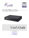
STEP 2 ..............
Connect the Computer cable supplied with GEN/ONE as follows:
DB-25 Male end to connector on back of GEN/ONE marked:
INPUT • COMPUTER
DB-23 Female end to connector on Amiga computer marked:
VIDEO or VIDEO PORT or RGB MONITOR
\l
:,'~{~
Ill
STEP 3 ..............
Connect a standard NTSC composite video source, such as from a
video camera or VCR to the BNC connector on the back of GEN/ONE
marked:
INPUT • VIDEO
Set the switch next to this connector to the 75 ohm position.
STEP 4 ••••••••••••••
Connect the short DB-9 male to DB-23 male cable, supplied with
GEN/ONE, to the connector on the rear panel of GEN/ONE marked:
OUTPUT • MONITOR
This jumper cable will now allow you to connect your existing RGB
monitor cable to GEN/ONE. Before purchasing GEN/ONE, this
cable was connected to the Amiga where GEN/ONE now connects.
GEN/ONE User's Manual
• Page 4
~'~
I
STEP 5 ••••••••••••••
-.
Connect a composite video monitor (not an ROB monitor) or VCR to
one of the outputs on the back of GEN/ONE marked:
OUTPUT - VIDEO
It is possible to use the Amiga monitors such as the 1080 and 1084
models as either an R GB or composite video monitor. See the manual
for your model for specific composite video connections and operation.
STEP 6 ••••••••••••••
Set the front panel switches on GEN/ONE as follows:
POWER: OFF
SYNC SOURCE: VIDEO
MODE: VIDEO
KEYING: NORMAL
STEP 7 ............. .
Plug the power transformer into a standard 110-120 Vac outlet.
STEP 8 ............. .
Turn the POWER switch to the ON position. The red powerindicator
will now light.
Look at you composite video monitor. You will see the incoming
video source which you connected to GEN/ONE 's video input. If you
haven't gotten this far, go back and recheck all the steps.
If you've noticed, we haven't even powered up the Amiga yet. What
you see is the incoming video being passed through to the output.
In the next step, we'll explain the operation of GEN/ONE. Leave
everything hooked up and running the way we described for now as
it will serve as our starting point in the next step. Make sure your input
video source is still active.
GEN/ONE User's Manual
- Page 5
STEP 9 ...•..........
Tum your Amiga ON and boot it up. Also, place the MODE switch
on GEN/ONE in the COMPUTER position.
The composite video output of GEN/ONE will display just the
Amiga's image. It will also be genlocked to the input video signal. If
you are also using an RGB monitor, it will show the Amiga's image
as well.
STEP 10 ••••••••••••
Flip the MODE switch to the OVERLAY position and toggle the
KEYING switch betw~n NORMAL and REVERSE.
On the composite video monitor, the Amiga's image will now be
overlayed over the input video signal. The RGB monitor will only
show the Amiga's image. It will do so regardless of the setting of the
MODE switch. As you flip the KEYING switch from NORMAL to
REVERSE, the overlay will reverse. More about this in a later
section.
STEP 11
••••••••••••
Return the switches to the following settings:
POWER: ON
SYNCSOURCE: VIDEO
MODE: COMPUTER
KEYING: NORMAL
The Amiga's image will now appear on the output.
Flip the SYNC SOURCE switch to the COMPUTER position.
GEN/ONE User's Manual
- Page 6
The composite video output will still show just the Amiga's image
but now it is "free-running" and not genlocked to the input video. To
prove this, remove the input video signal from the rear panel connector. The image will still be there on the composite monitor.
STEP 12 ............
Reconnect the input video signal. You can now operate GEN/ONE
in any of the modes described.
-
GEN/ONE User's Manual - Page 7
FRONT PANEL
SWITCHES
Let's go through the operation of GEN/ONE by explaining and using
the controls one by one. You should have GEN/ONE hooked up as
described in the installation section.
POWER
You already know what this is for.
MODE
Let's talk about the MODE switch first since the other two switches
depend on its setting.
VIDEO
In this position, GEN/ONE simply takes whatever video is present on
its video input and buffers it then passes it to the two VIDEO outputs
as well as seperates it into its Y (luminance) arid C (chrominace)
components for the Y and C outputs.
COMPUTER
In this position, GEN/ONE just encodes the ROB from the Amiga and
sends it to the outputs on the back of GEN/ONE.
It is in this mode, and only in this mode, that the SYNC SOURCE
switch becomes active. We'll talk about the SYNC SOURCE switch
in a moment.
OVERLAY
In this position, GEN/ONE overalys or "keys" the Amiga's video
image over the incoming video's image.
It is in this mode that the KEYING switch becomes active. We '11 talk
about this switch in a moment.
GEN/ONE User's Manual
• Page 8
I
SYNC SOURCE
First, remember that this switch is onl.v active when the MODE
switch is in the COMPUTER position.
The purpose of this switch is to determine what GEN/ONE will sync
or ''lock'' to when we just want to encode the ROB from the Amiga.
For example, let's say you don't have an external video source to
which to '' genlock' '; you just want to take the Amiga's output and put
it on tape or to a large screen projection TV.
In this case, first set the MODE switch to the COMPUTER position.
Then, set the SYNC SOURCE switch also to the COMPUTER
position and GEN/ONE will let the Amiga's video system "freerun'' without regard to any external video signal. In tum, GEN/ONE
will generate its own sync, blanking, and color burst derived from the
Amiga. Even if a video signal is present at the input video connector
of GEN/ONE, it will ignore it.
Let's take the second case where the SYNC SOURCE switch is in the
VIDEO position. Here, the Amiga will now be "genlocked" or
synchronized with the video signal present at the video input of GEN/
ONE.
Set the SYNC SOURCE switch to the VIDEO position and the
Amiga will genlock to the incoming video signal. The outputs will
just be the encoded ROB from the Amiga but it will now be
synchronous or "locked" to the input video signal.
Some operating points about this switch. As you can see, the purpose
of this switch is to tell the Amiga whether its video timing should be
"genlocked" (SYNC SOURCE switch in the VIDEO position) or
free run (SYNC SOURCE switch in the COMPUTER position).
Remember:
The SYNC SOURCE switch is only active when the MQDE switch
is in the COMPUTER position.
GEN/ONE User's Manual
- Page 9
As you can see from the above descriptions, the Amiga will be
genlocked to the input video in any of the following switch settings:
MODE
SYNC SOURCE
COMPUTER
OVERLAY
VIDEO
VIDEO
Don't Care
Don't Care
When in any of the genlock modes and the video signal is lost, the
Amiga will temporarily loose its main timing reference.
If this should happen, and no input signal is present to which to
genlock, just flip bruh the SYNC SOURCE and MODE switches to
the COMPUTER positions.
On the other hand, if the SYNC SOURCE switch is in the VIDEO
position, the output can be switched from computer-only to overlay
to video-only by changing the MODE switch.
KEYING
The KEYING switch is active only when the MODE switch is in the
OVERLAY position.
In the NORMAL position, Color 0 from the Amiga is substituted
with the input video signal to which GEN/ONE is locking.
In the REVERSE position, Color 0 from the Amiga will appear on
the output and all other colors will be substituted with incoming
video.
I
GEN/ONE User's Manual
• Page 1o
I
FRONT PANEL
CONTROLS
GEN/ONE provides several front panel controls that can either be
adjusted once at installation or from time to time at your option. They
are included to allow you to match GEN/ONE with the other video
equipment in your system. We have provided a small screwdriver to
allow you to adjust these multi-tum controls.
INPUT LEVEL
Three (3) 15-turn trimmer adjustments are provided on the front
panel, one each for RED, GREEN, and BLUE. These controls adjust
the level of the red, green, and blue (ROB) signals coming from the
Amiga. The levels can be independently adjusted from zero to unity
gain.
The purpose of these controls is twofold. First, they can be adjusted
to achieve proper color balance between the colors. With the aid of
a vectorscope, a known white signal image from the Amiga can be
made "white" by adjusting these ROB gain controls for minimum
chroma subcarrier on the composite video output. (Technically
speaking, white is not a color.)
-
The second use for these controls is to give you the capability of
intentionally "tinting" the composite video output so that it appears
to favor one color or hue. Maybe for some artistic reason you want
everything to appear a little more magenta in color. Just turn down
the GREEN level control so that the levels of RED and BLUE
(which makeup magenta) are relatively higher compared to green.
These controls are set at the factory for proper color balance. Caution
is urged when experimenting with these controls, without a vectorscope, so that you don't get things too far out of whack to the point
where you can't get the color back in balance.
Please note that the adjustment of these controls will effect the color
balance on the rear panel MONITOR output as well.
GEN/ONE User's Manual
- Page 11
h------------------------------------------
OUTPUT LEVEL
GEN/ONE has three different output types. There is a standard
NTSC composite video output available on two connectors on the
rear panel. There are also seperate Y (luminance) and C (chrominance) outputs which together comprise the S-VHS compatible Y/C
output.
The front panel OUTPUT LEVEL 15-turn controls for VIDEO, Y,
and C provide independent adjustment of the output levels from zero
to slightly more than unity gain.
SYSTEM TIMING
These three controls adjust the Horizontal (H), Vertical (V), and
Subcarrier (SC) timing of the encoded Amiga signal.
The H, V, and SC controls are only active when GEN/ONE is in one
of the genlocked modes described earlier.
The H and V controls will adjust when the horizontal and vertical
sync signals coming from the Amiga will start with respect to the sync
of the incoming video signal to which GEN/ONE is genlocking. This
is important to achieve accurate registration in the OVERLAY mode
of the Amiga's image over the incoming video.
The SC control will adjust the overall phase of the color subcarrier
portion of the Amiga's encoded signal with respect to the burst of the
incoming video.
GEN/ONE User's Manual
• Page 12
•
'"'t~ '
REAR PANEL
INPUTS
VIDEO
The VIDEO input is where a standard NTSC composite video signal
is connected to which the Amiga will genlock. This will also be the
video signal over which an Amiga generated image will be overlayed.
LOOP
This is a parallel connection of the VIDEO input and can be used to
send the input video signal on to other equipment in the system.
75 Ohm I LOOP
SWITCH
This switch will terminate the input video in 75 ohms which is
standard. If the LOOP connector is used to pass the video signal on
to other video equipment, then place this switch in the LOOP
position.
COMPUTER
This port connects to the Amiga's VIDEO port using the cable
supplied with GEN/ONE. This interconnecting cable must be kept
short due to the high speed 28 MHz clock that is sent to the Amiga
from GEN/ONE. Do not use a cable extender to lengthen the cable
supplied with GEN/ONE. Doing so, will cause the Amiga not to boot
or may cause erratic operation of the Amiga.
The pinout of this connector is given in Appendix A.
-
GEN/ONE User's Manual
• Page 13
REAR PANEL
OUTPUTS
VIDEO
Two independently buffered composite video outputs are provided
by GEN/ONE. These outputs will nominally produce a 1 Vp-p signal
(from sync tip to peak white) when terminated in 75 ohms. This level
can be adjusted by the front panel VIDEO control.
KEV
This is a buffered output from the color 0, or overlay, bit from the
Amiga. It is TTL compatible in level or can be terminated in 75 ohms.
It is always active regardless of the setting of the front panel MODE
switch. It's polarity will reverse with the setting of the front panel
KEYING switch.
This output can be used in conjunction with external special effects
generators.
v
This is the luminance only output of whatever you have selected to
appear on the composite VIDEO output. It has a nominal level of 1
Vp-p when terminated in 75 ohms. It's level can be adjusted by the
front panel Y control.
SC
This is the chrominance only output of whatever you have selected to
appear on the composite VIDEO output. It has nominally the same
levels of the chrominance portion of the VIDEO output when
terminated in 75 ohms. It's level can be adjusted by the front panel
C control.
GEN/ONE User's Manual
- Page 14
I
i
MONITOR
-
This is the buffered analog RGB and composite sync output from the
Amiga intended for hookup to an analog RGB monitor. It will only
display the Amiga's image and not the incoming video nor an overlay
of the two. It is always active regardless of the setting of the MODE
switch.
The analog RGB outputs on this connector are intended to be
terminated in 75 ohms and their level will be effected by the setting
of the front panel INPUT LEVEL controls.
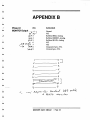
The pinouts for this connector are given in Appendix B.
·We recommended you use the short jumper cable provided with
GEN/ONE to convert this 9-pin connector to the same 23-pin
connector type that your RGB monitor previously connected to on the
back of your Amiga.
The pinout of this connector is nm compatible with the DB-9 to
circular DIN cable assembly supplied with the Amiga 1084 monitor.
That cable assembly is intended to connect an IBM PC to the 1TL
RGB input on the 1084.
GEN/ONE User's Manual
- Page 15
DOs AND DON'Ts
DO
..... make sure you have a video signal going into GEN/ONE whenever you are in any of the genlock modes. Without a proper video
signal to which to lock, the Amiga will not have a timing reference.
DO
..... make sure GEN/ONE is powered ON whenever it is connected to
the Amiga and the Amiga is ON, even if you don't want to genlock.
When GEN/ONE is connected to the Amiga, the Amiga expects to see
the master 28MHz clock to come from GEN/ONE. This can only
happen if GEN/ONE is powered ON .
DO
..... realize that the quality of the picture you will see on the composite
monitor will not look as sharp as the same image on the ROB monitor.
This is because whenever you encode from the Amiga into a composite video signal distortions will occur. Also, the TVs, VCRs, and
composite monitors, even Y/C equipment, does not have the same
bandwidth as an ROB monitor. It is this additional bandwidth that is
necessary to show all the fine detail. Also, the encoding of ROB into
composite video or YIC will add certain artifacts to the color portion
of the signal.
DON'T
..... lengthen the cable connecting the Amiga to the GEN/ONE. This
cable carries the 28MHz clock as well as other timing signals. If it is
lengthen by adding an extension cable or substituting a cable oflonger
length, the additional cable capacitance will cause the clock signal to
become too weak to properly drive the Amiga. The Amiga will then
exhibit erratic operation and may not boot at all.
DON'T
..... assume that because an ROB monitor cable mechanically will
connect from the MONITOR connector on GEN/ONE to your ROB
monitor that it is wired correctly. Just because it fits dosen't mean it
is wired correctly. The pinout for the GEN/ONE's MONITOR
connector is given in Appendix B of this manual. Compare it to the
equipment your connecting up to if you are making your own cable.
DON'T
... .. operate GEN/ONE along with any other genlock, such as the
Amiga A2300, at the same time. The Amiga was designed to handle
only one genlock at a time.
~
,,,!ji
GEN/ONE User's Manual
- Page 16
l
'
TAKING OFF THE
TOP COVER
Although there are no user adjustments inside GEN/ONE, if you must
take the cover off ple.ase note the following.
To take the top cover off, remove the four (4) screws that hold the
rubber feet to the co-m. These screws are located inside the feel
Once the feet are off,. just slide the cover off.
DO NOT remove the four screws attached to the bottom panel. These
will loosen the front and rear panels and may cause nuts and washers
to rattle around loose inside the unit. And we all know what will
happen then.
-
GEN/ONE User's Manual
- Page 17
OPTIONAL CABLE
ASSEMBLIES
Communications Specialties offers several interface cables for
integrating GEN/ONE into your video system. These cables are
available from your dealer or from Communications Specialties.
,:::~i
In addition to the cables listed here, we would like to know what other
cables you may feel are needed.
Part#
Input
Output
Length
Where Used
CAB-1
DB-9 male
4BNC plugs
4 feet
MONITOR Output
CAB-4
BNCplug
RCA plug
6 feet
VIDEO Input
or Output
CAB-10
2 BNCplugs 4-pin Mini
DIN plug
6 feet
Y/C Output to
S-VHS Input
CAB-12
BNCplug
BNCplug
6 feet
Any BNC Input
or Output
GEN/ONE User's Manual
- Page 18
ii
-
TROUBLESHOOTING
GEN/ONE is not your average genlock. With all the switches and
controls it's easy to get trapped into some strange mode. If you find
things aren't working as they should, here are some tips to try.
GET BACK
TO BASICS
Most of you will integrate GEN/ONE into a more complex video
system. It's important when troubleshooting a problem you believe
associated with GEN/ONE that you hookup all inputs and outputs
directly to GEN/ONE.
Do not go through any external equipment like VCRs, switchers,
processing amplifiers and TB Cs when trying to determine the source
of the problem. This will eliminate these connections as a possible
source of the problem and allow you to look at GEN/ONE as simply
as possible.
IS THE INPUT
GOING OUT?
Hook up a known video source, such as a color camera, to the input
of GEN/ONE and place the MODE switch in the VIDEO position.
Does this video source appear on the composite video output? If not,
check all the connections as well as the power transformer.
HOW ABOUT THE
AMIGA?
Put the MODE switch and the SYNC SOURCE switch in the
COMPUTER position. Remove all discs from the Amiga. Tum the
Amiga ON. You should see the Workbench requestor screen on the
composite video output and ROB monitor outputs of GEN/ONE. If
not, make sure the cable is connected from the Amiga to GEN/ONE.
Also, make sure that you are using only the cable supplied with GEN/
ONE to connect it to the Amiga.
TROUBLES WITH
THE RGB
MONITOR
By far the most common problem associated with the ROB MONITOR output of GEN/ONE is that the wrong cable is used. The DB9 cable supplied with the 1084 monitor will not work with GEN/ONE
even though it ''fits''. The MONITOR output is also wired differently then most other genlocks so don't use one of their cables either.
GEN/ONE User's Manual
- Page 19
The current version of GEN/ONE is supplied wtth a short Jumper
cable to interface the ROB MONITOR output of GEN/ONE with
your existng ROB monitor.
WHY DOES THE
OUTPUT LOOK
"NOISY" WHEN I
LOCK TO A VCR?
When you genlock to a VCR that is not time based corrected, any
genlock will have a hard time trying to "follow" the errors in the sync
and color burst signals coming off the tape. This is true of any VCR,
even the 1-inch broadcast machine's. That is why there are time base
correctors (TBCs). GEN/ONE will lock to a non-time based corrected VCR but the resulting Amiga image will exhibit a very slight
horizontal jitter. The colors, particularly magentas and reds, might
show broad horizontal streaks in them and appear to be generally
"noisy". This is because GEN/ONE is trying to lock to a video signal
which is inherently unstable. To demonstrate this, substitute a color
camera for the VCR which is a stable video source.
TECHNICAL
SUPPORT
When all else fails, ask your dealer for help. You can also contact us
by phone, FAX, or letter. We are here to help. We ha\'e a lot of
experience with different types of video systems and can help with
system integration problems. Your dealer is also a good person to
contact as he has had much experience with the Amiga.
Our phone number is (516) 273-0404 Monday to Friday 9 to 5
Eastern Time. Our FAX number is (516) 273-1638.
GEN/ONE User's Manual
• Page 20
;;·i~
ii
IF YOU RETURN
YOUR GEN/ONE
TO US FOR
REPAIR
We can't read minds. You would be surprised how often we get
equipment back for repair and find nothing is wrong. The real
problem is that we don't know what problem you, the user, were
experiencing that prompted the return in the first place.
The problem may be in your system interfacing or it may be some
intermittent problem inside GEN/ONE itself. But it's imperative llHlJ.
you tell us whatproblem you are exgeriencinf so that we can dig for
the problem ifit isn't obvious. If you can, we would appreciate a VHS
tape showing the problem if its a subtle one.
Also, please include a daytime phone number where we can contact
you in case we have any questions. Especially if you are returning
GEN/ONE through your dealer.
Remenber, we want to solve your problem but we need some help.
GEN/ONE User's Manual
- Page 21
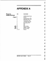
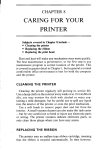
APPENDIX A
Pinout for
COMPUTER Input
FUNCTION
·1
~,,-2
3
4
5
6
7
8
9
~~~
~
12
13 - 25
28 MHz Master Clock
Ground
Composite Sync, TTL
Horizontal Sync, TTL
Vertical Sync, TTL
3.58 MHz Subcarrier
Zero Detect, TTL
N!C
N/C
RED, Analog
GREEN, Analog
BLUE, Analog
Ground
GEN/ONE User's Manual
- Page 22
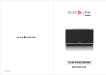
APPENDIX B
Pinout for
MONITOR Output
FUNCTION
PIN
l~l
~
Ground
N/C
Buffered RED, Analog
Buffered GREEN, Analog
Buffered BLUE, Analog
N/C
N/C
Composite Sync, TlL
Vertical Sync, TlL
ti' 2k
7£.-41' 3
lf~4
~5
)(
6
¢~x 1
?~g
~
/i>'t
x~9
-
-..
•
l
2
2.J
3
3
'1
'7
J
6
'
~=~;J
~
illl
-
''j
1
'1
I"'?
t.f,.
I~ "i. (
AJ. A? ./. ;"" .;; - )-,'~ .. ,pf ,.,f
4
.../-
A16?0
J41."" ..., '
GEN/ONE User's Manual • Page 23
l>s~
,t ~
(JI
~.tie
STATEMENT OF
LIMITED WARRAN TY
There are no warranties, expressed or implied, except as expressly set
forth herein.
Communications Specialties, Inc. (CSI) warrants that for a period of
one (1) year after purchase by the Buyer, GEN/ONE manufactured by
CSI will be free from defects in material and workmanship under
normal use and service. The Buyer shall give prompt written notice
of any claims of defect in materials. and workmanship.
A Return Material Authorization (RMA) number must be obtained
from CSI before any equipment is returned by the Buyer. All returned
material must be shipped to CSI, Hauppauge, New York, at the
expense and at the risk of the Buyer. Units returned to the Buyer will
be shipped freight collect.
CSI's obligation under this warranty will be limited, at its option, to
either repair or replacement of defective units, including free materials and labor, at its customer service facility in Hauppauge, New
York. In no event shall CSI be liable for any incidental or consequential damages or loss of profits or goodwill.
CSI shall not be obligated to replace or repair equipment that has been
damaged by fire, war, acts of God, or other similar causes, or
equipment that has been serviced, altered, or improperly installed, or
has been abused or has defaced serial numbers.
RMA numbers and repairs can be obtained from:
Communications Specialties, Inc.
89A Cabot Court
Hauppauge, New York 11788
Tel: (516) 273-0404
Fax: (516) 273-1638
GEN/ONE User's Manual
• Page 24