1
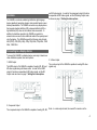
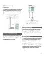
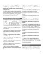
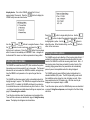
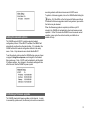
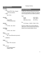
VM4HD Installation
and User Guide
1
Table of Contents
Important Safety Information
CAUTION: TO REDUCE THE RISK OF ELECTRIC SHOCK, DO
Overview.................................................................................... 3 NOT REMOVE COVER. NO USER SERVICEABLE PARTS
Connecting to a display device.................................................. 3 INSIDE. REFER SERVICING TO QUALIFIED SERVICE
Connecting an external video source........................................4 PERSONNEL.
Connecting to a network............................................................ 4
Using flash memory................................................................... 4
Understanding the front panel LED indicators...........................5
Using the setup menu................................................................5
Setting the time and date...........................................................6
Setting the video options........................................................... 6
Setting the network options.......................................................7
Performing a firmware upgrade................................................. 7
Hardware Specifications............................................................ 7
The lightning flash with arrowhead symbol, within an
equilateral triangle, is intended to alert the user to the
presence of insulated “dangerous voltage” within the
product’s enclosure that may be of sufficient magnitude to
constitute a risk of electric shock to persons.
The exclamation point within an equilateral triangle is
intended to alert the user to the presence of important
operating and maintenance instructions in the literature
accompanying the appliance.
CAUTION: Read this guide before you begin installation or
operation.
When using this unit, basic safety precautions should always be
followed to reduce the risk of fire, electrical shock, or personal injury.
• Read and understand all instructions.
• Follow all warnings and instructions marked on this unit.
• Do not use this unit near water, for example near a sink. Do
not install the unit in a wet or damp location.
• Mount the unit securely. Serious damage and/or injury may
result if unit falls.
• Do not cover the unit or cooling slots as it may cause
overheating. Never install unit near heaters, hot device or in
any place where proper ventilation is not provided.
2
•
•
•
•
•
•
•
Use only the power source marked on the unit.
Do not defeat the safety purpose of the polarized or
grounding-type plug. A polarized plug has two blades with
one wider than the other, a grounding type plug has two
blades and a third grounding prong. The wide blade or third
prong are provided for your safety. If the provided plug does
not fit into your outlet, consult an electrician for replacement
of the outdated obsolete outlet.
For safety purposes this unit is equipped with a grounded
power receptacle and cord. Do not defeat this safety feature
by tampering with the unit or plug.
Do not place objects on or crush the power cord. Install the
unit where no one can step or trip on the cord.
Never push any objects through slots in this unit. This may
result in the risk of fire or electrical shock. Never spill any
liquid on the unit.
To reduce the risk of electrical shock, do not disassemble the
unit. Take the unit to your dealer for service when service is
required. Opening or removing the cover may expose you to
dangerous voltages or other risks. Incorrect reassembly can
cause electrical shock when the unit is subsequently used.
Unplug the unit and power cord from power outlets and refer
servicing to an authorized dealer when any of the following
occur.
A. When power cord is damaged or frayed.
B. If liquid has been spilled into the unit.
C. If the unit has been exposed to rain or water.
D. If unit does not work properly by following the
operating instructions correctly.
E. If the unit has been dropped or physically
damaged.
F. If the unit exhibits a distinct change in
performance.
CAUTION:
• Only connect power after unit is mounted and all connections
have been made.
WARNING:
• To prevent the risk of fire or electrical shock, do not expose
this product to rain or any type of moisture.
• Unplug the unit from power if it emits smoke, an abnormal
smell or makes unusual noise. These conditions can cause
fire or electrical shock. Confirm that smoke has stopped and
contact an authorized dealer.
For best performance
•
•
Operating temperature: 32° to 95° F (0° to 35° C)
Non-operating temperature: -4° to 113° F (-20° to 45° C)
•
Relative humidity: 5% to 95% non-condensing
•
Keep the unit away from electrical noise generating devices,
such as fluorescent lamps and motors.
The unit should be kept free from dust, high temperature and
vibration.
The unit should not be operated in direct sunlight.
Do not place any objects on top of unit.
The unit should be kept away from heat sources such as
heaters, stoves and heat making electronic devices.
Do not install in damp basement or near equipment that
creates humidity.
•
•
•
•
•
Routine care
• Wipe the outer surface with a soft cloth. Do not use solvents,
thinners or any liquid. Do not use aerosols.
SAVE THESE INSTRUCTIONS
3
Overview
The VM4HD is a network enabled high definition digital signage
device capable of generating dynamic video content based on user
defined presentations. The VM4HD connects to any display device
that accepts standard definition (SD), enhanced definition (ED) or
high definition (HD) video via the onboard video connectors. In
addition to standalone operation, the VM4HD can genlock to
external video sources to allow additional media to be superimposed
onto the display. The VM4HD supports the following video formats:
480i (NTSC), 576i (PAL), 480p, 576p, 720p 50Hz, 720p 60Hz, 1080i
25Hz, 1080i 30Hz.
and HD video signals. In order for the component output to function
as expected with SD video signals, set the SD Analog Output mode
as shown on page 7, Setting the video options.
Connecting to a display device
To connect the VM4HD to a display device, commonly a television or
video distribution system, there are 4 options.
1. HDMI Output
The HDMI output of the VM4HD is capable of sending SD, ED, and
HD video signals along with stereo audio. In order for the HDMI
output to function as expected with SD video signals, set the SD
Output mode as shown on page 7, Setting the video options.
3. S-Video Output
The s-video output of the VM4HD is capable of sending SD video
signals only.
2. Component Output
The component output of the VM4HD is capable of sending SD, ED,
Note – in s-video output mode, the unused Pr connector on the
4
VM4HD will output composite video.
4. Composite Output
The composite output of the VM4HD is capable of sending SD video
signals only. When composite output is chosen, any of the three
video output connectors may be used to output a composite video
signal.
Connecting to a network
Connecting an external video source
The VM4HD connects to an external video source using the video
input, and stereo audio input connectors. If no presentation is
available, or the current presentation is paused, the external video
source will be passed through to the display.
If network operation is desired, the VM4HD must be connected to
the same local area network (LAN) as the computer running the
supplied VM Composer software. If you are unsure how to
accomplish this, contact your distributor or installer for assistance.
Using flash memory
The VM4HD stores presentations in external memory connected via
the SD card slot, or the front or rear USB connectors. Note – the
front and rear panel USB connectors may not be used
simultaneously.
The VM4HD must have a memory device connected in order to play
or download a presentation. Presentations can be pre-programmed
onto a memory device, or downloaded to the memory device over a
local area network (LAN) using the supplied VM Composer
software.
5
Once programmed with a presentation, the VM4HD will operate
8 – SD video source. This LED will be on if the VM4HD is
unassisted. When power is applied, the presentation will
genlocking to an external video source, and the detected format is
automatically start. When power is removed, the presentation stored SD.
in flash memory is safe.
9 – Internal video. This LED will be on if the VM4HD is generating
If the VM4HD is playing a presentation, it should be paused before
video internally, not locked to an external video source.
removing the memory device. Failure to do so could result in system
10 – Debug LED 1. See the troubleshooting section for more
errors. To pause the current presentation, press the
button on
information.
the front panel and wait for the Pause LED to turn on.
11 – Debug LED 3. See the troubleshooting section for more
information.
Understanding the front panel LED indicators
1 – USB activity. This LED will be on if the VM4HD recognizes a
connected USB drive.
2 – Memory warning. This LED will be on to warn the user that the
current presentation must be paused before removing the flash
memory.
3 – SD activity. This LED will be on if the VM4HD recognizes a
connected SD flash card.
4 – Ethernet activity. This LED will be on if the VM4HD is actively
downloading a schedule via ethernet.
12 – Debug LED 5. In normal operation, this LED will flash to
indicate the external source video format does not match the
presentation format. See the troubleshooting section for more
information.
13 – Genlock LED. This LED represents the genlock status of the
VM4HD. If solid on, the VM4HD is genlocked either to the external
video source, or internal video. If blinking, the VM4HD is not
genlocked. Note – the VM4HD must be genlocked to display video.
14 – Debug LED 2. See the troubleshooting section for more
information.
15 – Debug LED 4. See the troubleshooting section for more
information.
16 – Debug LED 6. See the troubleshooting section for more
information.
5 – USB source. This LED will be on if the current presentation is
being played from an attached USB drive.
17 – Pause LED. This LED represents the pause state of the
VM4HD. If on, the current presentation is paused, or there is no
presentation available for the VM4HD to play. If not on, the VM4HD
is currently playing a presentation.
6 – SD source. This LED will be on if the current presentation is
being played from an attached SD flash card.
Using the setup menu
7 – HD video source. This LED will be on if the VM4HD is
genlocking to an external video source, and the detected format is
HD.
To use the setup menu, first follow the instructions to connect the
VM4HD to a display device as shown on page 4, Connecting to a
6
display device. Turn on the VM4HD, and wait for it to boot,
approximately 30 seconds. Press the
button to display the
VM4HD setup menu as shown below.
Use the
and
buttons to navigate the menu. Press
the
button to enter a sub-menu, and press the
button to exit a sub-menu. Press the
button from anywhere
within the menu to immediately exit the menu. Note – changes will
be discarded if the menu is exit while a parameter is being edited.
Press the
button to begin editing the time. Use the
and
buttons to adjust the parameter being edited, which will
be highlighted in yellow. Use the
and
buttons to
adjust the value. When finished editing, use the
button to
return to the main menu.
Setting the video options
The VM4HD supports auto detection of the incoming video format. If
enabled, the auto detect engine will automatically switch the video
Setting the time and date
format of the VM4HD to match the incoming video format. Note – if
the incoming video format does not match the video format of the
The VM4HD has a real time clock (RTC) that maintains the system
currently playing presentation, the presentation will automatically
time when power is disconnected for up to two weeks. The time and
pause to prevent incompatible media from being displayed.
date must be set once when the VM4HD is installed, and again any
The VM4HD supports several different output configurations for
time the VM4HD is not powered on for a period longer than two
standard definition (SD) video. The SD Output setting must match
weeks.
the installation option chosen for video to display correctly. Note –
The VM4HD has timezone support, which automatically adjusts for
these selections are for SD formats only. HD video can only be
daylight savings if required. The VM4HD also supports network time
displayed via component output, or HDMI.
protocol (NTP). If enabled, the VM4HD will attempt to synchronize
to a network time server via the internet every time it turns on. Note To set the video options, enter the VM4HD setup menu as described
– an internet connection and valid network settings are required, see on page 6, Using the setup menu, and navigate to the Video Setup
sub-menu.
page 5, Connecting to a network.
To set the time and date, enter the setup menu and navigate to the
Time and Date sub-menu as described on page 6, Using the setup
menu. The display should appear as shown below.
7
a working network with internet access and a DHCP server.
To perform a firmware upgrade, turn on the VM4HD while holding the
button. All of the LEDs on the front panel will flash several times
to indicate that firmware upgrade mode is being entered, upon which
the button may be released.
Setting the network options
When the firmware upgrade is complete (could take up to 30
minutes), the VM4HD will automatically reboot and resume normal
operation. If after 30 minutes the VM4HD has not resumed normal
operation, power cycle the unit and contact your distributor or
installer for help.
The VM4HD supports DHCP, a widely supported network
configuration protocol. When DHCP is enabled, the VM4HD will
automatically configure the ethernet interface. If it is disabled, the
VM4HD will use the network configuration defined in the setup
menu. Note – Only advanced users should disable DHCP.
To set the network options enter the VM4HD setup menu as shown
on page 6, Using the setup menu, and navigate to the Network
Setup sub-menu. Note – DHCP must be disabled to edit the static
IP address settings. Any changes to the network settings will take
effect the next time the VM4HD is power cycled.
Performing a firmware upgrade
The VM4HD downloads firmware updates via the internet. In order
to successfully update a unit, the ethernet port must be connected to
8
20 watt typical, 35 watt max
Hardware Specifications
Video Output
3 x BNC
Component YPbPr, S-Video, or Composite
1v, 75 ohm source termination
1 x HDMI
Type-A full size
Mechanical Specifications
One Half RU wide, 1RU tall cast aluminum enclosure can be pan
mounted, table mounted (rubber feet included) or rack mounted with
second unit (coupling kit with rack ears available through distributor)
Weight
Video Input
3 x BNC
Component YPbPr
1v, 75 ohm terminated internally
Unit only
Shipping
Master container (10 units)
2.47 lb / 1120.37 g
3.68 lb / 1669.21 g
39 lb / 17690.1 g
Size
Audio Input
2 x BNC
2v, 10k ohm
W, H, D inch (mm)
stereo, line level
Audio Output
2 x BNC
2v, 220 ohm
stereo, line level
8.65 (220), 1.75 (44.5), 7.5 (190)
Supplied in box- VM4HD, power cord, software installation disc,
startup instructions, rubber mounting feet and simple instructional
labeling for hook-up and operation (applied to enclosure).
Memory
2 x Type-A USB
Note – only one USB connector may be used at a
time
1 x SD/SDHC Slot
Network
1 x RJ-45
Ethernet 10/100, auto cossover
Power
1 x IEC socket
3 wire, grounded and polarized
100-240vAC, 50/60hz
9
Warning on copyrights and product usage.
WARRANTY AND REMEDIES SET FORTH ABOVE ARE EXCLUSIVE
AND IN LIEU OF ALL OTHERS, ORAL OR WRITTEN, EXPRESS OR
IMPLIED.
No dealer, agent, or employee is authorized to make any modification,
extension, or addition to this warranty.
S&S Research Inc. IS NOT RESPONSIBLE FOR SPECIAL, INCIDENTAL,
OR CONSEQUENTIAL DAMAGES RESULTING FROM ANY BREACH OF
WARRANTY, OR UNDER ANY LEGAL THEORY, INCLUDING LOST
PROFITS,DOWNTIME, GOODWILL, DAMAGE OR REPLACEMENT OF
About the S&S Research Inc License Agreement and Limited
EQUIPMENT AND PROPERTY AND COST OF RECOVERING
Warranty on Software
REPROGRAMMING, OR REPRODUCING ANY PROGRAM OR DATA
TO PERSONS WHO PURCHASE OR USE THIS PRODUCT: carefully read STORED IN OR USED WITH S&S Research Inc. PRODUCTS.
all the terms and conditions of the license agreement presented to you
Some states do not allow the exclusion or limitation of implied warranties or
when you install the software. Using the software or this documentation
liability for incidental or consequential damages, so the above limitation or
indicates your acceptance of the terms and conditions of that license
exclusion may not apply to you. This warranty gives you specific legal
agreement. S&S Research Inc. is not responsible for third party software
rights, and you may have other rights which vary from state to state.
that may be used in the operation of the VM4HD. Refer to dealer, distributor
or software developer for further support and or upgrades.
Television programs, films, videotapes, and other materials may be
copyrighted. Unauthorized recording of such materials may be contrary to
the provisions of the copyright laws. S&S Research Inc. is not responsible
for materials supplied by third party vendors or by any persons or entities.
S&S Research Inc. is not responsible for the installation or implementation
of this device.
Limited Warranty on Hardware
S&S Research warrant this equipment against defects in materials and
workmanship for a period of One (1) Year from the date of original retail
purchase. This warranty applies only to hardware products; Software is
licensed and warranted pursuant to separate written statements. If you
discover a defect, first write or call your distributor for information on
service. No service will be performed on any product returned without prior
authorization. S&S Research Inc. will, at its option, repair or replace the
product at no charge to you, provided you return it during the warranty
period. You must use the product’s original packing material for in shipment,
and insure the shipment for the value of the product. Please include your
name, address, telephone number, a description of the problem, and the
original, dated bill of sale with the returned unit and print the Return
Merchandise
This warranty does not apply if the equipment has been damaged by
accident, abuse, misuse, or misapplication; has been modified without the
written permission of S&S Research Inc, or if the product serial number has
been removed or defaced.
ALL IMPLIED WARRANTIES, INCLUDING IMPLIED WARRANTIES OF
MERCHANTABILITY AND FITNESS FOR A PARTICULAR PURPOSE,
ARE LIMITED IN DURATION TO ONE (1) YEAR FROM THE DATE OF
THE ORIGINAL RETAIL PURCHASE OF THIS PRODUCT. THE
10
DECLARATION OF CONFORMITY
Trade Name:
Model No.:
Responsible Party:
Address:
responsible for compliance could void the user's authority to operate the
equipment.
S&S Research Inc.
Video Messenger VM4HD
S&S Research Inc.
89 Access Rd.#10
Norwood MA. U.S.A.
This device complies with Part 15 of the FCC Rules. Operation is subject to
the following two conditions: (1) This device may not cause harmful
interference, and (2) this device must accept any interference received,
including interference that may cause undesired operation. This equipment has
been type tested and found to comply with the limits for a class B digital
device, pursuant to Part 15 of the FCC Rules. These limits are designed to
provide reasonable protection against harmful interference in a residential
installation. This equipment generates, uses, and can radiate radio
frequency energy and, if not installed and used in accordance with the
instruction manual, may cause harmful interference to radio
communications. However, there is no guarantee that interference will not
occur in a particular installation. If this equipment does cause interference
to radio or television equipment reception, which can be determined by
turning the equipment off and on, the user is encouraged to try to correct
the interference by any combination of the following measures:
• Relocate or reorient the receiving antenna
• Increase the separation between the equipment and the receiver
• Plug the equipment into an outlet on a circuit different from that to which
the receiver is connected If necessary, you can consult a dealer or
experienced radio/television technician for additional
assistance.
PLEASE NOTE: only equipment certified to comply with Class B
(computer input/output devices,
terminals, printers, etc.) should be attached to this equipment, and it must
have shielded interface
cables in order to comply with the Class B FCC limits on RF emissions.
WARNING: changes or modifications to this unit not expressly approved
by the party
11