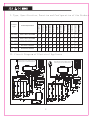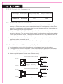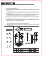
1
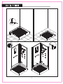
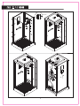
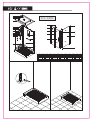
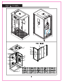
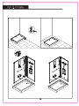
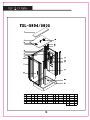
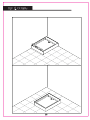
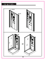
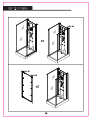
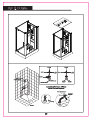
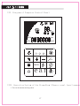
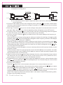
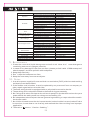
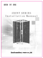
COUNT SERIES
Installation Mannual
Dear users:
Thank you for selecting our “Count” series steam room
(Shower Room). For your safety, please read this manual
carefully before installing and using the product.
C ont e nts
I
Type, Specification, Function and Configuration of the P
II
Circuit Diagram of Electrical Appliance
III
Electricity Parameters
IV
Installation of Electrics
V
VI
VII
VIII
Installation of Water-supply Appliance
Installation of the Room
Diagram of Computer Control Panel
Operation System of the Steam Room (Shower Room)[Operating
instructions]
IX
X
XI
Troubleshooting
Maintenance
Notes
S tate m ent
We expressly reserve the right to make modifications of
t h i s m a n u a l , e v e n w i t h o u t d u e n o t i c e . We r e s e r v e t h e f i n a l
explanatory right.
1
I. Type, Specification, Function and Configuration of the Product
Functions and Configuration
Product
Type
Product Specification
Telephone
Ceiling lamp
Speaker
Ventilation fan
Cosmetology mirror
Radio
Three Gear Tap
Ozone
Temperature Display
Top spray
Pin-type massage
Handle shower
YSL-5801
900*1000*2200mm
*
*
*
*
*
*
*
*
*
*
*
*
YSL-5802
900*1200*2200mm
*
*
*
*
*
*
*
*
*
*
*
*
YSL-5803
1250 * 800 *2180mm
*
*
*
*
*
*
*
*
*
*
*
*
YSL-5804
900 * 950 * 2180mm
*
*
*
*
*
*
*
*
*
*
*
*
YSL-5805
900 * 950 * 2180mm
*
*
*
*
*
*
*
*
*
*
*
*
II. Circuit Diagram of Electrical Appliance
Wiring Diagram of Color & White Lights on
the Sensory Screen of the Steaming Room
C
C
Wiring Diagram of Color & White Lights on
the Sensory Screen of the Shower Room
Mln
MHZ
MEN
TEL:
MEN
Mln
TEL:
MHZ
TUN
VOL
MEN
TUN
VOL
ENSLI
MEN
ENSLI
Wiring Diagram
of Computer
Panel
2
III. E le ctri c ity P ar a mete r s
Rated voltage
Rated frequency
Voltage of output lamp
Voltage of control circuit
220-240V
50-60hz
12V
12V
IV. I nst alla t ion o f Electr ics
1. The indoor power devices must conform to national safety standards. The voltage and
frequency of the power source must match the electricity requirement of the product.
S p e c i f i c a l l y, l e a k a g e c i r c u i t b r e a k e r s h a l l b e i n s t a l l e d a n d v e r i f i e d . U s e r s s h a l l n o t
modify or change any part of this product.
2. The power of Steam room (Shower room) shall use fixed wire and the power line shall
have 3 conductors. The cross-sectional area of each conductor shall not less than
1 . 5 m m ( t h e r e f o r e , 3 X 1 . 5 m m2 ) . W h e n g o i n g t h r o u g h t h e w a l l , t h e p o w e r l i n e s h a l l b e
protected with protection pipe for safety.
3. C o n n e c t t h e e a r t h w i r e o f t h e S t e a m r o o m ( S h o w e r r o o m ) a n d t h a t o f o t h e r e l e c t r i c
appliances of the house and test it.
4. U s e r s s h a l l n o c h a n g e t h e l i n e s o f t h e S t e a m R o o m ( S h o w e r r o o m ) i n c a s e o f a n y
damage to it.
V. Insta llat i on of Wa ter- s upp l y Ap p lia n ce
1.The installation must strictly follow the hot and cold water label on the product.
2. It is suggested to install corner valve at inlet for maintenance and service thereafter.
3 . T h e w a t e r s u p p l y p r e s s u r e o f t h i s p r o d u c t s h a l l b e 0 . 1 - 0 . 4 M PA . N o r m a l w o r k o f t h e
product shall be affected if the pressure is out of this scope.
4. Water-supply diagram of Steam room (Shower room).
Common Steaming Faucet of 3 Levels
Pin-type massage
Hot water
HOT
Top spray
COLD
OFF
Inlet valve Steamer
Cold water
Steam outlet
Handle shower
Common Shower Faucet of 3 Levels
Pin-type massage
Hot water
HOT
Top spray
COLD
OFF
Cold water
Handle shower
3
V I . I n s t a l l a t i o n o f t h e R oom
1. Select a place for installation. Move the bathtub to the selected place and adjust the
screws on the bottom with the assistance of level gauge until they are level. Then tighten
the screw and install drain pipe.
2. Move the bathtub and leave some place for the operation of the installation personnel.
3. Fix the glass clip with M5x25 flat screws, and tighten the door hinge and the basin with
M6x50 flat screws.
4. Place the rear panel of the cabin onto the basin, and tighten the aluminum alloy column
and the basin respectively with M4x10 and M4x14 half-round self tapping screw through
the preset holes.
5. Place the two fixing glass panels on the basin, fix them with M4x20 flat screws and the
skirt brim through the preset holes and the aluminum alloy column, and then tighten them
with M5x16 flat screws unto the glass clip having been tightened to the basin.
6. Put the cover on the installed room and tighten the M4X14 cup head self tapping screws
in the preset holes.
7. Put the glass panel for the movable door between the top and bottom hinges, insert a
leather spacer in the front and other spacers in the back, and tighten with screws.
8. Fix the plastic door stopper onto the movable door and the fixed glass, and install the
water blocking bar onto the movable glass door.
9. Install the top lamp, ventilation fan, computer control panel according to the labels on
the circuit.
10. Connect cold and hot water pipe (please install them following the labels on the product).
Turn on the power, and insert the drain pipe into the sewer.
11. Move the room to the selected place and the installation is finished. (Please refer to
the image below)
1
2
3
Installation tools
YSL-5801
4
26
5
22
6
7
a
b
Level gauge
Wrench
18
8
28
19
c
Teflon tapes
d
27
9
10
11
12
13
23
14
24
29
20
30
Cross Screwdriver
15
g
h
Straight Screwdriver
21
16
Electro probe
25
17
e
Rubber hammer
f
Hexagonal head
wrench
No.
Name
Quantity No.
Name
Quantity No.
1
Trumpet
1
6
Right room body
1
11
Sprinkler hose
1
16
Drainer
1
21
Stool
1
26
Door hinge
2
2
Ozone Box
1
7
Handle shower
1
12
Temperature sensor
1
17
Bottom basin
1
22
Side column
2
27
Fixed glass
1
3
Electric fan
1
8
Single layer storing frame
1
13
Brass sprinkler joint
1
18
Left room body
1
23
Plastic door stopper
2
28
Water blocking bar
1
4
cover
1
9
Mike
1
14
Square brass sprayer
6
19
Computer control panel
1
24
Fixed glass
1
29
Moveable room glass
1
5
Poker
1
10
Square handler
1
15
Brass steam outlet
1
20
Tower rack
1
25
Glass clip
2
30
Door handle
1
4
Name
Quantity No.
Name
Quantity No.
Name
Quantity No.
Name
Quantity
M4X10
M4X10
C
M EN
EA
RL
M4 X14
5
M 4 X20
C
MEN
I
SL
EN
C
MEN
I
SL
EN
Cold water
inlet pipe
6
Hot water
inlet pipe
1
2
3
YSL-5802
4
26
22
5
6
7
27
8
16
9
10
11
12
13
14
17
28
23
29
24
30
18
15
19
20
25
21
No.
Name
Quantity No.
Name
1
Trumpet
1
6
Right room body
1
11
Sprinkler hose
1
16
Name
Quantity No.
Name
Right room body 1
21 Bottom basin
2
Ozone Box
1
7
Handle shower
1
12
Temperature sensor
6
17
Computer control panel
1
22
3
Electric fan
1
8
Single layer storing frame
1
13
Brass sprinkler joint
1
18
Tower rack
1
4
cover
1
9
Mike
1
14
Square brass sprayer
1
19
Stool
5
Poker
1
10
Square handler
1
15
Brass steam outlet
1
20
Drainer
7
Quantity No.
Name
Quantity No.
Quantity No.
Name
Quantity
1
26
Door hinge
2
Side column
2
27
Fixed glass
1
23
Plastic door stopper
2
28
Water blocking bar
1
1
24
Fixed glass
1
29
Moveable room glass
1
1
25
Glass clip
2
30
Door handle
1
M4X 10
M 4 X10
C
M EN
EA
RL
M 4 X1 4
M4X 2 0
C
M EN
EA
RL
EA
RL
8
TUN
VOL
EA
RL
Col
dw
H o t w a te r in
a
ter i
nle
t pip
le t p ip e
e
Y SL - 58 03
21
16
9
1
17
18
19
2
3
20
10
11
4
5
12
13
6
7
8
14
15
S.N
NAME
Q.T
S.N
NAME
Q.T
S.N
NAME
Q.T
S.N
NAME
Q.T
S.N
1
trumpet
1
5
temperture sensor
1
9
electric fan
1
13
square brass
sprayer
6
17
side column
2
2
poker
1
6
tower rack
1
10
single layer
storing frame
1
14
drainer
1
18
fexed glass
2
bottom basin
1
19
door handle
1
4
20 moveable glass 1
3
handle shower
1
7
foot massager
1
11
mike
1
15
4
computer control
panel
1
8
brass steam
outle
1
12
square handle
1
16
9
track
NAME
Q.T
? 4X14
10
? 4X10
11
YSL-5804/5805
1
13
2
3
4
14
15
5
6
7
8
9
16
10
EN
SL
I
17
18
11
19
12
20
21
N AME
Q.T
S.N
NA M E
Q. T
S. N
co v er
1
5
p o ker
1
9
2
g las s roo f 1
6
ra i l
6
3
top l a mp
1
7
h and sho w er
4
t r ump e t
1
8
le f t o r
ri g ht g l as s
1
Q. T
S. N
fr o nt c o rn e r
pi l lar
2
13
10
r o tat i ng s haf t
2
1
11
f ron t g l a ss
2
12
do o r h a ndl e
12
NA M E
Q.T
S.N
1
17
14
d e cor a tiv e c o v er2
18
po k er
1
1
15
19
ste a m o u t l e t
1
1
16
bac k co r ner
2
pil lar
com p ute r c o n tro l
1
pa n er
20
dra i ner
1
21
bo t tom b a s i n
1
N A ME
el e ctr i c f a n
NAM E
Q.T
b a ck j e t 6
13
4X 10 ( 5 )
4X 10 (5 )
C
EN
SL
I
ME
N
EN
SL
I
4X 10 ( 5 )
EN
SL
I
EN
4X14 (3)
14
SL
I
? 4X 10 ( 5 )
EN
? 4X10 (5)
? 4 X 1 0 ( 5)
EN
15
SL
I
SL
I
EN
SL
I
EN
Top spray
Shower
SL
I
Top spray
Back
Sprayer
Back
Sprayer
Shower
Steamer
Hot water inlet pipe
Cold water inlet pipe
10 0
20 0
Hot water inlet pipe
Cold water inlet pipe
15
0
1
Hot water
inlet pipe
0
1380
30
Cold water
inlet pipe
50
Installation Scheme of Water
Valve Connecting Pipe
700
Water drainage of basin
21
0
16
Sewer pipe of
the steamer
0
Drainer 60
16
V II. D iag ram o f Co m put e r Co ntr o l Pa n el
C
MEN
Mln
TEL:
MHZ
TUN
VOL
MEN
earl
VIII. Operation System of the Steam Room (Shower room).(user’
s m anual
1. Turn on the water mixing valve.
17
A.Scheme of mixing valve
Pin-type massage
Pin-type massage
Hot water
Hot water
HOT
HOT
Top spray
COLD
OFF
COLD
OFF
Cold water
Inlet valve
Top spray
Steamer
Steam outlet
Handle shower Cold water
Handle shower
B. Turn the valve to left or right to adjust the water cold or hot, and rotate according
to your demand.
1. Function of the master switch on the computer panel: press the
key to start, initiate other
functions, and at the same time the roof light is turned on. Press the key for a second time
to turn off all functions.
2. Roof light: Press the
key to turn on the roof light, and press for a second time to turn off
the light. When the light is on, the corresponding letter will appear on the LCD screen.
3. Function of fan: Press the
key to start the fan, and the corresponding letter will appear
on the LCD screen; press the key for a second tie to turn off the fan.
4. Function of radio: Press the
key and wait till the LCD screen displays the frequency to
turn on the radio.
Press the TUNVOL key to change radio program; when you enter into the setting of changing radio
program, press
key to automatically change the radio frequency and the LCD displays
the current frequency value (87-108MHz).
Press the TUNVOL key to change the volume; when you enter into the volume setting, press
key to automatically change the volume and the LCD displays the current volume (0-10).
Call stored programs: when the radio is on and it is not in any setting state, press
key
to call out the stored programs.
Press the MEN key to store programs, and you can story the current frequency into the current
program number.
Press automatic search to store programs. Press and hold MEN key for 2 seconds, the radio
frequency will scan from 87.0MHz to 108.0MHz to store all scanned radio programs into
the positions from 0-15 respectively.
5. Alarm function: press the
key to open the alarm function, the loudspeaker beeps, and at
t h e s a m e t i m e , t h e r o o f l i g h t a n d f a n a r e o n ; i f t h e s a u n a f u n c t i o n i s o n , p l e a s e t u r n o ff i t ;
press the key for a second time to turn off the alarm function.
6. Telephone function: press the
key to open the telephone function, and at the same time
press
key to adjust the volume of the telephone (0-10). Press the key for a second time
to turn off the telephone function.
7. Function of the steamer:
Press the
key to turn on the steamer, and press it for a second time to turn it off.
Press the
to adjust the time, after entering into the time setting, press
key to adjust
the running duration of the steamer in the scope of 1-90 minutes.
Press the
key to adjust temperature, press
key after entering the temperature
setting to adjust the temperature in the cabin from 25-60 Celsius degree.
(Note: The computer panel of the shower cabin is the same as that of the steaming cabin,
Except for the steaming function)
I X . Tro ubl esh oot ing
18
Problems
Reason
The plug doesn’
t p roperly c onnected
Circuit breaker of the power line is breaking
No power
The wire connecting the control panel is in poor contact.
The steaming sauna key is ill in function or not pressed.
The heating pipe of the steaming generator is out of function
There is not water into the steaming generator
No steam
The bellows linking the steaming generator is blocked or ruptures.
Insufficient heating time
The temperate in the steaming cabin is too low
Low water pressure
The shower doesn’t
The switch for cold/hot water is off
work
The outlet of the shower is blocked.
Water level sensor does not work
Water bleeds from the
steaming outlet
The water feeding solenoid valve does not work well
The joints are poorly sealed
Water leakage
The joints are broken
Water pipe is broken
The light is damaged
The line is off
The roof light is not on
The current stabilizer is out of function
The computer control panel is out of function
The ventilation fan is out of function
The ventilation fan
The line is off
does not work
The computer control panel is out of function
Wrong place of the antenna
Radio has no station
The switch is off
No surfing
Air control valve is off
Poor surfing
Thermostat tap gives no hot water Valve core is blocked
The water is not warm enough The valve is blocked or the temperature isn’t a djusted h igh e nough
Remedy
firmly connect the plug and the jack.
Restart
Re-connect it.
Replace or press the key
Replace the pipe
Check the water feeding valve and the cold and hot water switch
Dredge or replace it
Prolong heating time
Adjust the temperature setting
Add one supercharging pump
Turn on the switch for cold/hot water.
Remove the blockage or replace the shower
Check the water level sensor
Replace
Reseal
Replace
Replace
Replace
Link it
Replace
Replace or repair
Replace
Link it
Replace or repair
Adjust the antenna
Turn on the switch
Turn on the valve
Clean the valve core
Remove the blockage and adjust the temperature valve.
X. M ainten a n c e
1 . C l e a n t h e r o o m w i t h l i q u i d d e t e r g e n t s a n d s o f t c l o t h . N o t e : d o n’t u s e d e t e r g e n t s
containing acetone or hydrogen peroxide.
2. In case of any damage of the room surface, please polish it with 1500# waterproof
abrasive paper, and then polish it with toothpaste.
3. Keep the product dry.
4. Don’t wipe the hardware too often.
5. Keep the room away from coarse objects.
XI . N otes
1. It must be power-supplied from a residual current device (RCD) with the rated working
residual current below 30mA.
2. If the flexible cord is broken, it must be replaced by our personnel from our company or
other repair organizations to avoid risks.
3. The fixed wiring should be equipped with an all-pole disconnection device.
4. The earthing device should be linked to the fixed wiring permanently.
5. No fittings with electrified parts should touch people in the bathtub unless they are
powered with the safety extra low voltage not exceeding 12V.
6. No independent electrical part that can generating steaming or vapor should be used in
the shower cabin.
7. No child is allowed to use the device unattended unless he/she has received sufficient
instructions, known how to use it safely, and realized the risks resulting from improper
application.
8. The mark of
means “Caution: Scalding”.
19