1
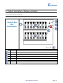
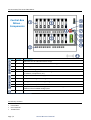
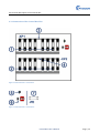
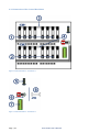
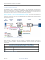
Central
Central-Box
User’s Manual
Edition 4.0
June 2011
Documentation History
Edition
1.0
2.0
3.0
4.0
Revision / Supplement
First Edition November 2010
New edition February 2010: completely revised
New edition November 2010: completely revised
June 2011: New logo
Edition 4.0
PADCON reserves the right to make alterations to its products in the interest of technical progress. These
alterations need not be documented in every single case.
This manual and the information contained herein have been compiled with due diligence. However,
PADCON assume no liability for printing or other errors or damages arising from such errors.
The brand names and product names used in this document are trademarks or registered trademarks of the
respective title owner.
Page | 2
Central-Box User’s Manual
Content
Central-Box User’s Manual ..................................................................................................................................1
Documentation History ........................................................................................................................................2
Content .................................................................................................................................................................3
1. Introduction ......................................................................................................................................................5
1.1 Usage ..........................................................................................................................................................5
2. Product description / Delivery contents...........................................................................................................7
2.1 Overview of the Central-Box Plus ..............................................................................................................7
2.2 Overview of the Central-Box Minus ...........................................................................................................8
2.3 Delivery contents .......................................................................................................................................8
3. Technical data and documents.........................................................................................................................9
3.1 Specifications .............................................................................................................................................9
3.2 Dimensions of the Central-Box ............................................................................................................... 10
4. Installation / Connection ............................................................................................................................... 11
4.1 Installation............................................................................................................................................... 11
4.1.1 Place of installation ........................................................................................................................ 11
4.1.2 No direct weather influence........................................................................................................... 11
4.1.3 Cable connection ............................................................................................................................ 11
4.1.4 Installation of the housing.............................................................................................................. 12
4.1.5 Mechanical installation of the Central-Box .................................................................................... 12
4.1.6 Horizontal mounting ...................................................................................................................... 12
4.1.7 Realize drip off loop for inputs ....................................................................................................... 12
4.1.8 Cable conduct ................................................................................................................................. 12
4.2 Installation............................................................................................................................................... 12
4.3 Terminal description of the Central-Box ................................................................................................. 13
4.3.1 Connection of the Central-Box Plus ............................................................................................... 13
4.3.2 Connection of the Central-Box Minus ............................................................................................ 16
4.3.3 Mounting rail for cable strain reliefs .............................................................................................. 20
5. Function ......................................................................................................................................................... 21
5.1 The Central-Box collects supply lines from the TGA-Boxes Pro .............................................................. 21
5.2 The Central-Box fuses the supply lines against fault current.................................................................. 21
5.3 The Central-Box protects PV plants against surge voltage on the DC side ............................................. 21
5.3.1 Evaluation of the surge arresters of the Central-Box ..................................................................... 21
Central-Box User’s Manual
Page | 3
5.4 Monitoring (String current and string voltage) ....................................................................................... 22
5.4.1 String current measurement .......................................................................................................... 22
5.4.2 Evaluation of the voltage monitoring............................................................................................. 23
6. Function check ............................................................................................................................................... 25
6.1 General checks ........................................................................................................................................ 25
6.1.1 Visual check .................................................................................................................................... 25
6.1.2 Mechanical check ........................................................................................................................... 25
6.1.3 Electrical check ............................................................................................................................... 25
6.2 Check of the plus and minus string fuses ................................................................................................ 25
6.2.1 Visual check .................................................................................................................................... 25
6.2.2 Electrical check ............................................................................................................................... 25
6.3 Collecting function of the Central-Box ................................................................................................... 26
6.3.1 Visual check .................................................................................................................................... 26
6.3.2 Mechanical check ........................................................................................................................... 26
6.4 Electrical check ........................................................................................................................................ 26
6.5 Protection against surge voltages ........................................................................................................... 26
6.5.1 Visual check .................................................................................................................................... 26
6.5.2 Electrical check ............................................................................................................................... 26
6.6 Disconnection function between inverter and PV plant ......................................................................... 27
7. Fault analysis / Decommissioning ................................................................................................................. 28
7.1 Fault analysis ........................................................................................................................................... 28
7.2 Decommissioning and demounting of the Central-Box .......................................................................... 28
8. Safety instructions ......................................................................................................................................... 29
9. Maintenance.................................................................................................................................................. 31
10. Spare parts................................................................................................................................................... 32
11. Service / Contact.......................................................................................................................................... 33
Page | 4
Central-Box User’s Manual
1. Introduction
1.1 Usage
The PADCON Central-Box is an array combiner used as a device for collecting of the individual supply lines
from the TGA boxes of the photovoltaic plant. The DC supply lines collected in the Central-Box are led to the
inverter via a collecting main.
Figure 1: Central-Box - Overview
The Central-Box is always mounted in pairs, in each case one box for plus and minus, to guarantee a safe
build-up.
The consequent focusing of the construction for durability is reflected in the clear layout, the use of high
quality components and the specific design for outdoor operation.
Padcon optionally offers the RealTime monitoring system for the Central-Box.
There are two types of the Central-Box, the Central-Box Plus and the Central-Box Minus. The Central-Box
Plus is used for collecting up to 14 Plus supply lines from the TGA-Boxes. The Central-Box Minus is used for
collecting up to 14 Minus supply lines from the TGA-Boxes.
Additional the voltage of the collecting mains is monitored in the Central-Box Plus. As well the voltage of the
collecting mains as the current of the supply lines coming from the TGA-Boxes are monitored in the CentralBox Minus.
Central-Box Plus
•
•
•
The Plus supply lines from the TGA-Boxes are collected in the Central-Box Plus.
Up to 14 DC supply lines can be attached in the Central-Box Plus.
The supply lines are fused by NH1 fuse links.
Central-Box User’s Manual
Page | 5
•
•
The supply lines are protected against surge voltage.
The voltage of the collecting mains is monitored.
Central-Box Minus (with current and voltage monitoring)
•
•
•
•
•
•
The Minus supply lines from the TGA-Boxes are collected in the Central-Box Minus.
Up to 14 DC supply lines can be attached in the Central-Box Minus.
The supply lines are fused by NH1 fuse links.
The supply lines are protected against surge voltage.
The current of the 14 supply lines is monitored.
The voltage of the collecting mains is monitored.
Page | 6
Central-Box User’s Manual
2. Product description / Delivery contents
2.1 Overview of the Central-Box Plus
Central-Box
Plus Components
Cypher
Number
Description
14
NH1 fuses for the individual plus strings.
2
Collecting mains.
2
Fuses for the surge voltage arresters.
1
Terminal block for the surge arrester monitoring.
1
Fuse for the voltage monitoring line to the Central-Box Minus.
2
Surge arresters for the DC supply lines.
1
Bus bar for the PE connections. Placed in the Central-Box Plus base.
Table 1: Central-Box Plus - Components
Central-Box User’s Manual
Page | 7
2.2 Overview of the Central-Box Minus
Central-Box
Minus Components
Cypher
Number
Description
14
NH1 fuses for the individual minus strings.
14
Current converters for the individual minus string current measurement.
2
Collecting mains.
2
Fuses for the surge voltage arresters.
1
2
Terminal block: surge arrester monitoring and the connection of the different sensors
(irradiation, temperature, etc.).
Surge arresters for the DC supply lines.
2
Fuses for the voltage monitoring line to the Central-Box Plus.
1
Voltage converter for the string voltage measurement.
1
3 way isolation amplifier: 4-20 mA -> 0-10 V
1
Adapter board for the DC string currents and the DC voltage measurement and
additional free available analog inputs.
Bus bar for the PE connections. Placed in the Central-Box Minus base.
1
Table 2: Central-Box Minus - Components
2.3 Delivery contents
•
•
•
Central-Box
User’s Manual
14 NH1 fuses
Page | 8
Central-Box User’s Manual
3. Technical data and documents
3.1 Specifications
HOUSING
Open field installation
UV resistance
Material
Properties
Coloring
Mounting
Yes
Yes
Fiber glass reinforced polyester
High flame resistance, weatherproof
RAL 7035
On foundation base
INPUT VALUES
Max. valid DC voltage (UDC Max)
Number of DC inputs per box
String connection
Fuse
Max. valid DC current (IMax)
≤ 1000 V
max. 14
Cable lug M10
63A – 250A
140 A
OUTPUT VALUES
Main connection
Number of DC outputs
Max. output current (IDC tot)
Protective conductor connection
Cable lug M12
2
max. 2 x 540A
16 mm² - 120 mm²
DIMENSIONS AND WEIGHT
Cabinet: Width/Height/Depth [mm]
Base: Width/Height/Depth [mm]
Weight
1115 / 1100 / 327
1115 / 902 / 310
ca. 80 kg (depends on configuration)
STANDARDS
CE conformity
Yes
PROTECTIVE CLASS AND ENVIRONMENTAL
CONDITIONS
Protection class conforming to EN 60529
Valid surrounding temperature (T in °C)
Rel. air humidity non condensing ( U Air)
Max. height above mean sea level (MSL)
IP 44
-25 °C…+40 °C
up to max. 90%
1.000 m
FURTHER PROPERTIES
Over voltage protection
Monitoring
Type 2, (Type 1 optional)
Current and voltage (optional)
Central-Box User’s Manual
Page | 9
3.2 Dimensions of the Central-Box
Figure 2: Cabinet dimensions
Figure 3: Base dimensions
Page | 10
Central-Box User’s Manual
4. Installation / Connection
Danger:
Danger to life by electric shock !
High DC voltages are applied to different
differe components of the Central-Box:
•
All operations described in this chapter excludedly may be led through by qualified technical personal. Qualified
means that the personal is trained appropriately to the task.
All safety notes mentioned in the user’s manual have to be observed during operations at the Central-Box.
Central
•
If you are not able to remove an error with help of this manual,
manual, please immediately contact PADCON.
•
4.1 Installation
4.1.1 Place of installation
•
•
•
•
Easily accessible.
Connections have to be accessible.
accessible
No constraining
training objects in immediate surrounding.
surrounding
Allow possibility for yearly maintenance (mowing the lawn, cleaning housings,…).
4.1.2 No direct weather influence
•
•
•
Avoid direct, strong sun irradiation.
Protect against direct rain.
Protect against standing water.
4.1.3 Cable connection
•
•
•
•
Outputs on the side.
Inputs at the bottom.
Observe correct string assignment.
assignment
Retighten cable glands.
Central-Box User’s Manual
Page | 11
4.1.4 Installation of the housing
•
•
•
Mount housing tension free.
Avoid
id mechanical tension by screws.
Adjust mechanical tensions with buffers if necessary.
necessary
4.1.5 Mechanical
cal installation of the Central-Box
•
•
•
Solid and even mounting surface.
Observe complete rest of the flange area of the optional available mounting
mounting brackets.
Use all four fastening screws.
4.1.6 Horizontal mounting
•
Check mounting and repair if necessary.
necessary
4.1.7 Realize drip off loop for inputs
•
•
Imply reserve.
No horizontal cable routing.
4.1.8 Cable conduct
•
•
•
id mechanical tension of inputs.
Avoid
Conduct cables
bles without mechanical tension.
Avoid crossings in wiring.
4.2 Installation
1.
2.
3.
4.
5.
5.
6.
7.
8.
Disconnect the inverter on the AC side.
Switch the inverter currentless on the DC side.
Mount the Central-Box.
Connect the protective earth conductor.
con
Connect the inputs of the Central-Box.
Central
Connect the outputs of the Central-Box
Central
with the inverter.
Switch on the current on the DC side.
si
Put the inverter into operation.
We recommend to check the polarity and height of voltage of the strings before installation and to
calibrate the input values
lues of the inverter after installation.
Danger:
The five safety rules !
The five safety rules:
•
•
•
•
•
Page | 12
Disconnect
Secure against restart
Check absence of voltage
Earth and short circuit
Fence off and cover adjacent, live parts
Central-Box User’s Manual
4.3 Terminal description of the Central-Box
4.3.1 Connection of the Central-Box Plus
Figure 4: Central-Box Plus – Connection 1
Figure 5: Central-Box Plus – Connection 2
Central-Box User’s Manual
Page | 13
Central-Box Plus – terminal description
String supply lines to the NH1 fuses of –WP1
Screw connection
1 to 7
Signal description
String supply lines 1 to 7
String supply lines to the NH1 fuses of –WP2
Screw connection
8 to 14
Signal description
String supply lines 8 to 14
Collecting main of –WP1
Screw connection
1
Signal description
Collecting main of –WP1
Collecting main of –WP2
Screw connection
1
Signal description
Collecting main of –WP2
Surge arrester communication: -X0
Spring terminal
1
2
Signal description
Remote signal: contact 1 (noc)
Remote signal: contact 2 (noc)
Voltage measurement to Central-Box Minus: -F1C
Screw terminal
1
Signal description
Central-Box Plus is connected with Central-Box Minus for the voltage
measurement. This connection is established between the fuse –F1C of
the Central-Box Plus and the fuse –F2C of the Central-Box Minus. At this
point here the connection for the Central-Box Plus is attached to the screw
terminal of fuse –F1C.
PE bus bar (in the Central-Box base)
Screw terminal
1 to 10
Signal description
Up to 10 screw terminals can be sticked to the PE bus bar for the
necessary PE connections.
Table 3: Central-Box Plus – Terminal description
Page | 14
Central-Box User’s Manual
Note:
Observe tightening torque !
The torque of the individual lines mentioned below has to be observed during connection.
Cable cross sections and torques
Line
Connection type
Cross
section
Thread
diameter
Torque
Supply line
Collecting main
Protective conductor
Control and
communication lines
Screw connection
Screw connection
Screw terminal
Spring terminal
16 – 95 mm2
16 - 120 mm2
16 – 120 mm2
0,75 – 2,5
mm2
M10
M12
M10
-
25 Nm
32 Nm
32 Nm
-
Table 4: Central-Box – Cable cross sections and torques
Central-Box User’s Manual
Page | 15
4.3.2 Connection of the Central-Box Minus
Figure 6: Central-Box Minus – Connection 1
Figure 7: Central-Box Minus – Connection 2
Page | 16
Central-Box User’s Manual
Central-Box Minus – terminal description
String supply lines to the NH1 fuses of –WM1
Screw connection
1 to 7
Signal description
String supply lines 1 to 7
String supply lines to the NH1 fuses of –WM2
Screw connection
8 to 14
Signal description
String supply lines 8 to 14
Collecting main of –WM1
Screw connection
1
Signal description
Collecting main of –WM1
Collecting main of –WM2
Screw connection
1
Signal description
Collecting main of –WM2
Terminal block
-X1 – Surge arrester monitoring
Spring terminal
Signal description
1
2
-15V
0V
0V
+15V
24V
PE
Surge arrester monitoring: contact 1 (ncc)
Surge arrester monitoring: contact 2 (ncc)
Power supply
Power supply
Power supply
Power supply
Power supply
Protective earth
-X2 – Sensors (irradiation, temperature, etc.)
Spring terminal
Signal description
21
22
2
PE
24V
0V
3
PE
24V
0V
4
PE
24V
0V
4
3 way isolation amplifier: 4-20 mA -> 0-10 V: minus input
3 way isolation amplifier: 4-20 mA -> 0-10 V: plus input
3 way isolation amplifier: 4-20 mA -> 0-10 V: measuring signal
Protective earth
Sensor 3: Power supply
Sensor 3: Power supply
Sensor 3: measuring signal
Protective earth
Sensor 4: Power supply
Sensor 4: Power supply
Sensor 4: measuring signal
Protective earth
Sensor 5: Power supply
Sensor 5: Power supply
Sensor 5: measuring signal
Central-Box User’s Manual
Page | 17
PE
Protective earth
-X3 – Power supply
Spring terminal
Signal description
24V
24V
24V
0V
0V
0V
Power supply
Power supply
Power supply
Power supply
Power supply
Power supply
Voltage measurement to Central-Box Plus: -F1C
Screw terminal
1
Signal description
Central-Box Plus is connected with Central-Box Minus for the voltage
measurement. This connection is established between the fuses –F1C of
the Central-Box Plus and the fuse –F2C of the Central-Box Minus. At this
point here the connection for the Central-Box Minus is attached to the
screw terminal of fuse –F2C.
Voltage / current converter - Adapter board PSC 1.1
-X1 – Power supply
Screw terminal
Signal description
1
2
3
0V power supply
+15V power supply
-15V power supply
-X2 – Analog inputs for free use
Screw terminal
Signal description
1
2
3
4
5
6
7
8
9
10
11
12
13
14
15
16
0V potential for analog inputs.
0V potential for analog inputs.
0V potential for analog inputs.
0V potential for analog inputs.
0V potential for analog inputs.
0V potential for analog inputs.
0V potential for analog inputs.
0V potential for analog inputs.
Analog input 1: freely available.
Analog input 2: freely available.
Analog input 3: freely available.
Analog input 4: freely available.
Analog input 5: freely available.
Analog input 6: freely available.
Analog input 7: freely available.
Analog input 8: freely available.
-X3 (RJ45) – Analog inputs for the current converter evaluation for string
current measurement
Pin
Signal description
1
0V potential for the analog signals of the converters for string current
measurement.
Current converter at supply line 1 of –WM1: 0 – 4 VDC
Current converter at supply line 2 of –WM1: 0 – 4 VDC
Current converter at supply line 3 of –WM1: 0 – 4 VDC
Current converter at supply line 4 of –WM1: 0 – 4 VDC
Current converter at supply line 5 of –WM1: 0 – 4 VDC
2
3
4
5
6
Page | 18
Central-Box User’s Manual
7
8
Current converter at supply line 6 of –WM1: 0 – 4 VDC
Current converter at supply line 7 of –WM1: 0 – 4 VDC
-X4 (RJ45) – Analog inputs for the current converter evaluation for string
current measurement
Pin
Signal description
1
0V potential for the analog signals of the converters for string current
measurement.
Current converter at supply line 8 of –WM1: 0 – 4 VDC
Current converter at supply line 9 of –WM2: 0 – 4 VDC
Current converter at supply line 10 of –WM2: 0 – 4 VDC
Current converter at supply line 11 of –WM2: 0 – 4 VDC
Current converter at supply line 12 of –WM2: 0 – 4 VDC
Current converter at supply line 13 of –WM2: 0 – 4 VDC
Current converter at supply line 14 of –WM2: 0 – 4 VDC
2
3
4
5
6
7
8
-X5 (RJ45) – Analog inputs for the current converter evaluation for string
current measurement
Pin
Signal description
1
0V potential for the analog signals of the converters for string current
measurement.
Current converter at supply line 15 of –WM2: 0 – 4 VDC
Current converter at supply line 16 of –WM2: 0 – 4 VDC
Analog-input 17: freely available.
Analog-input 18: freely available.
Analog-input 19: freely available.
Analog-input 20: freely available.
Analog-input 21: freely available.
2
3
4
5
6
7
8
-X6 (RJ45) – Analog inputs for the current converter evaluation for string
current measurement
Pin
Signal description
1
0V potential for the analog signals of the converters for string current
measurement.
Analog-input 22: freely available.
Analog-input 23: freely available.
Analog-input 24: freely available.
Analog-input 25: freely available.
Analog-input 26: freely available.
Analog-input 27: freely available.
Analog-input 28: freely available.
2
3
4
5
6
7
8
PE bus bar (in the Central-Box base)
Screw terminal
1 to 10
Signal description
Up to 10 screw terminals can be sticked to the PE bus bar for the
necessary PE connections.
Table 5: Central-Box Minus – Terminal description
Note:
Observe tightening torque !
The torque of the individual lines mentioned below has to be observed during connection. See Table 4: Central-Box – Cable cross
sections and torques.
Central-Box User’s Manual
Page | 19
4.3.2.1 Configuration of the PSC 1.1
Note:
PSC 1.1 adapter board !
1.
2
Not used inputs has to be connected with groung during connection of the PSC 1.1 adapter board.
The freely available analog inputs have to be connected from the bottom to the top.
Figure 9: Connect analog inputs from bottom to top
Figure 8: Bridge analog inputs
4.3.3 Mounting rail for cable strain reliefs
Both following figures show the rail by which the strain relief of the supplied and led away lines can be
realized.
Figure 10: Central-Box – Mounting rail
Page | 20
Figure 11: Central-Box – Strain relief
Central-Box User’s Manual
5. Function
5.1 The Central-Box collects supply lines from the TGA-Boxes Pro
The PADCON Central-Box is an array combiner used as a device for collecting of the individual supply lines
from the TGA boxes of the photovoltaic plant. The DC supply lines collected in the Central-Box are led to the
inverter via a collecting main.
5.2 The Central-Box fuses the supply lines against fault current
Additionally the individual supply lines (plus and minus) are fused in the Central-Box by NH1 fuses against
overcurrent, reverse current and earth fault current.
5.3 The Central-Box protects PV plants against surge voltage on the DC side
The Central-Box protects the PV plant against surge voltage with help of surge arresters. 4 message windows
are placed on the 4 surge arresters (2 Central-Box Plus, 2 Central-Box Minus) used in the Central-Box that
indicate the state of the surge arresters. A green message window indicates that the surge arrester is
operational. A red message window indicates that the surge arrester is out of operation. That means that an
incorrect surge voltage occurred, that the surge arrester has tripped and has to be changed.
5.3.1 Evaluation of the surge arresters of the Central-Box
The surge arrester of the Central-Box is evaluated by a remote signal contact (ncc).
Surge arrester – Remote signal contact
Status
Contact closed
Beschreibung
Operational
Contact
opened
Inoperative when one of the message windows indicate red !
Table 6: Remote signal contact
Additional for evaluation of the surge arrester states message windows are placed on the 6 surge arrester
modules, that indicate the state of the corresponding modules. See 6.5 Protection against surge voltages.
Central-Box User’s Manual
Page | 21
5.4 Monitoring (String current and string voltage)
5.4.1 String current measurement
The Central-Box is used for string monitoring. The current of each individual string is measured for this
purpose by a current converter in the Central-Box Minus and the analog measured value is transmitted into
the Sensor-Box. The measured values are digitized in a cRIO controller in the Sensor-Box and transfered via
the communication line into the control station of the photovoltaic power plant.
Figure 12: Evaluation of the current measurement in the Sensor-Box illustrates the interconnection the
string current measurement in the Central-Box Minus and the transfer respectively the further processing of
the measured current value.
Figure 12: Evaluation of the current measurement in the Sensor-Box
Besides the voltage of the collecting mains also the current of the 16 supply lines (from the TGA-Boxes) is
monitored in the Central-Box Minus. The measured values of the monitored current are made available at
terminal –XM1.
Current monitoring in the Central-Box Minus
Tap
Input current value
range
Measured signal value
range
1 current converter per supply line (= 16 current converters)
0 to 100 ADC
0 to +4 VDC
Table 7: Current monitoring – Signal evaluation
Page | 22
Central-Box User’s Manual
5.4.2 Evaluation of the voltage monitoring
The voltage applied to the collecting mains in the Central-Box Plus and the Central-Box Minus is monitored
with a sensor and the measured value is made available at terminal –XM1. The plus potential of the voltage
is measured at –WP1 in the Central-Box Plus. The minus potential of the voltage is measured at –WM1 in the
Central-Box Minus. A connection is established between Central-Box Plus and Central-Box Minus for voltage
measurement.
The both monitored voltage potentials are (i.e. the plus and the minus pole of the voltage measurement):
• The voltage at the collecting main of terminal –WP1 of the Central-Box Plus.
• The voltage at the collecting main of terminal –WM1 of the Central-Box Minus.
This voltage is converted in the Central-Box Minus with the help of a voltage converter and the measured
value is made available at terminal –XM1. For the voltage measurement a line is led from terminal –WP1 of
the Central-Box Plus into the Central-Box Minus.
Figure 13: Central-Box – String voltage measurement gives a basic overview of the string voltage
monitoring, that is measured between the collecting mains of the Central-Box Plus and the Central-Box
Minus.
Figure 13: Central-Box – String voltage measurement
Central-Box User’s Manual
Page | 23
Voltage monitoring of the collecting mains
Central-Box Plus
Tap
Input voltage value
range
Measured signal value
range
Collecting main terminal –WP1
0 bis 1000 VDC
0 bis +10 VDC
Central-Box Minus
Tap
Input voltage value
range
Measured signal value
range
Collecting main terminal –WM1
0 to 1000 VDC
0 to +10 VDC
Table 8: Voltage monitoring – Signal evaluation
Page | 24
Central-Box User’s Manual
6. Function check
6.1 General checks
6.1.1 Visual check
•
•
•
•
•
Completeness of wiring
Snap in of the clips
Proper input wiring
Proper fit of connectors
Possible danger for man and material
6.1.2 Mechanical check
•
•
Tight fit of fuses
Tightening torque of cable glands
6.1.3 Electrical check
•
•
•
Check correct string assignment
Appropriate string current flow . See 7. Fault analysis / Decommissioning.
Appropriate open circuit voltage. See 7. Fault analysis / Decommissioning.
6.2 Check of the plus and minus string fuses
6.2.1 Visual check
•
•
•
Visible damages in and outside of the housing
Proper installation of the fuses
Surge arrester indicator on „Green“
6.2.2 Electrical check
•
•
Current flow via earth
Current flow/current direction
Central-Box User’s Manual
Page | 25
6.3 Collecting function of the Central-Box
6.3.1 Visual check
•
•
•
Function of the string fuses
Proper connection of the inputs
Proper connection of the outputs
6.3.2 Mechanical check
•
•
Proper sealing of the cable glands
Firm hold of the connection / the connection terminal
6.4 Electrical check
•
•
Polarity of current direction
Compare input and output current
6.5 Protection against surge voltages
6.5.1 Visual check
The Central-Box protects the PV plants against surge voltages on the DC side. Message windows are placed
on the surge arresters, that indicates the states of the surge arrester.
Surge arrester – Message window
State / Color
Green
Description
Operational.
Red
Inoperative if one of the message windows indicates red !
Table 9: Message window
The surge arrester has to be replaced if one of the 4 surge arresters (2 Central-Box Plus, 2 Central-Box Minus)
of the Central-Box has tripped, to guarantee surge protection furthermore. See 7. Fault analysis /
Decommissioning.
•
•
•
Message window state
Proper connection of the surge arrester
Possible danger for man and material
6.5.2 Electrical check
Page | 26
Central-Box User’s Manual
•
•
Earth fault current
Voltage applied to the surge arrester
6.6 Disconnection function between inverter and PV plant
•
•
Function of the string fuses
Function of the surge arrester
Central-Box User’s Manual
Page | 27
7. Fault analysis / Decommissioning
7.1 Fault analysis
Fault analysis
Visual inspection
Fault description
Measure
Damage of the housing.
Damage of the cable glands.
Damage of the cables.
Damage of the NH1 fuse bases.
Damage of the terminal blocks.
Damage of the PSC1.1 adapter board.
The housing has to be changed.
The cable glands have to be changed.
The cables have to be changed.
The NH1 fuse bases have to be changed.
The terminal blocks have to be changed.
The PSC1.1 adapter board has to be changed.
Voltage check
Nominal voltage nonexistent.
Polarity reversal.
The wiring has to be checked
ecked.
Correct polarity.
Current check - Polarity
The current of the inputs must be equal to the output
current.
Polarity reversal.
The wiring has to be checked
ecked.
Correct polarity.
Ground fault error – Insulation fault
Ground fault error.
Check if the attached voltage
oltage is higher than
1000 VDC. If not, replace the surge arrester.
Table 10: Fault analysis
7.2 Decommissioning and demounting of the Central-Box
Danger:
Danger of life by electrical shock !
High DC voltages are attached to the different components of the Central-Box.
•
•
•
1.
2.
3.
4.
5.
6.
All works described in this manual must exclusively be executed by qualified technical personal. Qualified means that
the personal has to be trained corresponding the task that has to be executed.
All safety instructions mentioned in the user’s manual have to be obtained working on the Central-Box. The personal
has to be familiar with the content of the user’s manual.
If you can not repair an error with help of this manual,
manual, immediately contact PADCON.
Disconnect the inverter on the AC side.
Switch the inverter currentless on the DC side.
Disconnect the outputs of the Central-Box
Central
from the equipment.
Disconnect the inputs of the Central-Box
Central
from the generator.
Disconnect the earthing.
Demount the Central-Box.
Page | 28
Central-Box User’s Manual
8. Safety instructions
General
1.
2.
3.
4.
The Central-Box only must be opened and installed by trained electrotechnical specialists
Consider the installation instructions in this manual
Consider the installation instructions of the used inverters and other connected devices
Consider the standards and rules as
• BGV A1/A2: Common trade association safety instructions for electrical installations / equipment
• DIN VDE 0100-712: Solar photovoltaic power supply systems (requirements for industrial premises, rooms and plants)
• VDI 6012 VDI Guide line: Decentralised energy systems in buildings, photovoltaic
• IEC 62548/ IEC82/514/CD: Installation and safety requirements for photovoltaic (PV) generators
• DIN VDE 0100-534
5. Inspect the Central-Box for damages before installation, that can prevent the functional and safety operation of the Central-Box
6. In case of violation of the installation instructions mentioned in this manual expires the warranty and the liability
Validity
This documentation describes how to install and operate a Central-Box.
Target group
This documentation is intended for installers and operators of PV systems which are realized with the Central-Box.. It includes a description of how to
install, operate the Central-Box.
Explanation of the Symbols Used
In this document, the following terms and symbols are used to describe different hazard levels:
Danger indicates a hazardous situation which, if not
avoided, will result in death or serious injury.
Danger
Warning indicates a hazardous situation which, if not
avoided, could result in death or serious injury.
Warning
Caution indicates a hazardous situation which, if not
avoided, could result in minor or moderate injury.
Caution
Storage of documentation
This operating manual, the installation guide, the data sheets, the operating manuals of installed components, and the wiring diagrams must be kept
in the immediate vicinity of the Central-Box.. They must be available to operators and maintenance staff at all
a times.
Failures and correction
Failures that can affect the safety, have to be removed immediately. Impermissible change and the use of spare parts, that are not recommended
from PADCON can cause fire, material damage or electrical shocks. Unauthorized
d persons must nut have access to this devices. Instruction labels have
to be readable properly and have to be replaced immediately if damaged.
Central-Box User’s Manual
Page | 29
Appropriate usage
Appropriate use of the Central-Box means following all instructions in the installation manual relating to installation, electrical connection, and
commissioning of the equipment. Any deviation from the instructions in this manual is regarded as inappropriate use of the equipment. PADCON
accepts no responsibility or liability for any and all damage resulting from inappropriate use of the equipment.
Appropriate use of the equipment also entails:
• Observation of the safety instructions listed here and in the following sections
• Observation of the instructions in the user manual
• Conformance to the device-dependent
dependent technical data
Personnel
Only qualified technical personnel may perform any and all work on the Central-Box.. Qualified means that the personnel must possess training
relevant to the activity performed and must be familiar with the content of this manual. The personnel must have read and understood the safety
section in this manual.
About this manual
This manual was written with the greatest possible care. However, discrepancies cannot be excluded. PADCON accepts no responsibility
respons
or liability for
injury to persons, or material damage caused by mistakes in this manual.
Checking the delivery
Upon receipt of the equipment, check the packaging and the device for any possible damage and compare the contents of the delivery
del
with the
delivery documentation. In the case of damage to the device and/or unclear delivery contents, please immediately contact PADCON GmbH (see
contact address on the last page).
Storage
The PADCON Central-Box may only be stored in rooms protected from dust and moisture.
Installation
The requirements relating to the installation site, the manner of installation and the mounting position must be observed. In addition to this, the
following points must be noted.
•
The installation location must be easily accessible
acce
and offer a secure base for working on the device. This is especially important for roofroof
mounted systems.
•
The Central-Box is built using the latest technology, according to recognized safety standards. Despite this, a fault resulting in arcing cannot
can
be
ruled out. This can result in melting of the enclosure as well as fire and smoke, which may represent a hazard to personnel or
o equipment. This
must be taken into consideration upon installation.
•
The equipment may not be installed near to inflammable materials. If this cannot be avoided, preventative measures must be taken, which
prevent fire and smoke from spreading.
•
The equipment may not be installed in critical areas, escape routes, living spaces or office spaces.
Special Hazards of Photovoltaic Systems
Photovoltaic systems have special characteristics representing special hazards that are described here. An active power source
sourc is connected, which
means that depending on the operating mode there may be voltage present, from the photovoltaic generator
generator and/or the Central-Box. This is
especially important to note when disconnecting the Central-Box. High DC voltages are connected (no zero-crossing),
crossing), that in case of error, or
unproper use of fuses or connectors, may result electric arcs. The short-circuit
cuit current of the photovoltaic generator is only slightly higher than the
maximum operating current and is also dependent on the level of solar radiation, which means that if a short circuit occurs in
i the system, the existing
circuit breakers are not guaranteed
ranteed to switch off. A highly branched generator array may be difficult to disconnect if a fault develops (e.g. short
circuit). We recommend the additional use of the optionally available DC circuit breaker for disconnecting the inverter.
Changes, modifications or additions of the Central-Box
Danger:
Danger in case of changes, modifications or additions of any components of the
Central-Box !
No changes, modifications or additions of any components of the Central-Box are allowed without prior agreement of Padcon.
Page | 30
Central-Box User’s Manual
9. Maintenance
Danger:
Danger to life by electric shock !
High DC voltages are applied to different
differe components of the Central-Box:
•
All operations described in this chapter excludedly may be led through by qualified technical personal. Qualified
means that the personal is trained appropriately to the task.
All safety notes mentioned in the user’s manual have to be observed during operations at the Central-Box.
Central
•
If you are not able to remove an error with help of this manual,
manual, please immediately contact PADCON.
•
Following table gives an overview of the different maintenance working that have to be led through at the
Central-Box
Box and the recommended maintenance interval.
Central
Central-Box
- Maintenance
Maintenance working
Check the terminal clamps of the power wiring for solidity and retighten
if required. Visually check the insulation and the terminals. Thereby look
after changes and discoloring of the material. Immediately change
c
defect
or corroded lines and contacts.
Check the terminal clamps of the string wiring for solidity and retighten
if required. Visually check the insulation and the terminals. Thereby look
after changes and discoloring of the material. Immediately change
c
defect
or corroded lines, contacts and connectors.
Check the correct and horizontal mounting of the Central-Box.
Central
Check the locks of the cover of the Central-Box
Central
for free movement and
correct function.
Check the cable glands for tightness and firm fit. Immediately change
defect or untight cable glands.
Check if condensed water has accumulated in the Central-Box.
Central
Check the earth connection respectively the contact resistance of the
protective conductor.
The function of the voltage converter has to be checked.
The wiring of the voltage converter has to be checked.
The function of the current converters has to be checked.
The wiring of the current converters has to be checked.
Check the ventilation membrane for pollution respectively damage.
Immediately change a defect or damaged ventilation membrane.
Check the fuses after removal from the fuse holders.
Check the surge arresters of the Central-Box.
Central
Check the DC contactors for proper function.
Check the mounting place of the Central-Box
Central
for easy access, secure
stand and flammable materials.
Maintenance
interval
12 month
12 month
12 month
6 month
6 month
6 month
12 month
12 month
12 month
12 month
12 month
12 month
12 month
12 month
12 month
12 month
Table 11: Central-Box maintenance
Central-Box User’s Manual
Page | 31
10. Spare parts
Following spare parts are available for the Central-Box:
•
•
•
•
•
Fuse
Fuse base
Cable gland
Housing lock
Tools
Page | 32
Central-Box User’s Manual
11. Service / Contact
PADCON GmbH
Steigweg 24, Gebäude 44
97318 Kitzingen
Germany
Tel: +49 (0) 9321.2680-200
Fax: +49 (0) 9321.2680-9200
E-Mail: info(at)padcon.com
www.padcon.com
Service and Complaint
Your primary point of contact for any service issues is Sascha Machner with his
competent team.
Tel: +49 (0) 9321.2680-222
e-mail: service(at)padcon.com
Central-Box User’s Manual
Page | 33


![Régulateurs (PDF/1,26Mo) [F]](http://vs1.manualzilla.com/store/data/006367628_1-d11067c6e30136a71de027b5803c5ae5-150x150.png)
![Indicateurs (PDF/782Ko) [F]](http://vs1.manualzilla.com/store/data/006364555_1-61d6515c96ce437ed2545f3e53fb26c1-150x150.png)