1
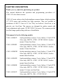
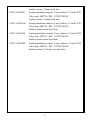
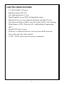
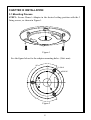
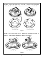
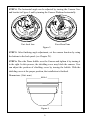
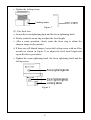
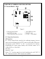
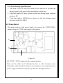
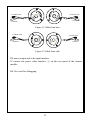
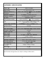
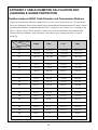
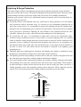
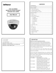
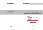
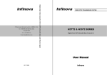
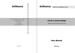
V5411-A2 SERIES
INDOOR COLOR DOME CAMERA
User Manual
CONTENTS
Chapter I Description .......................................................................... 1
Chapter II Main Features ................................................................... 3
Chapter III Installation ....................................................................... 4
3.1 Mounting Process ....................................................................... 4
3.2 Handling Precautions ................................................................. 7
3.3 Installation Precautions .............................................................. 7
Chapter IV Camera Function Setting................................................ 9
4.1 Camera Module – Back .............................................................. 9
4.1.1 Operation Instruction......................................................... 9
4.1.2 Lens Driving Signal Selection ........................................ 11
4.2 Power Board ............................................................................. 11
Appendix I Specification ................................................................... 13
Appendix II Cable Diameter Calculation and Lightning &
Surge Protection ................................................................................. 14
CHAPTER I DESCRIPTION
Thank you very much for purchasing our product.
This manual addresses the operation and programming procedures of
V5411-A2 color dome camera.
V5411-A2 series indoor color fixed minidome cameras feature a high-resolution
1/3" CCD sensor and excellent low light operation. They are available in
resolutions of 480 TV lines at 0.3 lux. They are built-in a fixed lens or an
auto-iris vari- focal lens. The cameras are designed for surface mount with
2-axis adjustment and require 12VDC/24VAC for power. The cameras provide
excellent image quality along with ease of installation.
This manual is for the following models:
V5411-A2004ST
Analog minidome camera, 2-axis, Indoor, 1/3 inch CCD,
Color only, 480TVL, NTSC, 12VDC/24VAC, Surface
mount, 2.8mm fixed lens
V5411-A2004SU
Analog minidome camera, 2-axis, Indoor, 1/3 inch CCD,
Color only, 480TVL, NTSC, 12VDC/24VAC, Surface
V5411-A2004SW
Analog minidome camera, 2-axis, Indoor, 1/3 inch CCD,
Color only, 480TVL, NTSC, 12VDC/24VAC, Surface
mount, 3.6mm fixed lens
mount, 6mm fixed lens
V5411-A2004SX
Analog minidome camera, 2-axis, Indoor, 1/3 inch CCD,
Color only, 480TVL, NTSC, 12VDC/24VAC, Surface
mount, 8mm fixed lens
V5411-A2004SB
Analog minidome camera, 2-axis, Indoor, 1/3 inch CCD,
Color only, 480TVL, NTSC, 12VDC/24VAC, Surface
mount, 2.5-6mm vari-focal lens
V5411-A2014ST
Analog minidome camera, 2-axis, Indoor, 1/3 inch CCD,
Color only, 480TVL, PAL, 12VDC/24VAC,
1
V5411-A2014SU
Surface mount, 2.8mm fixed lens
Analog minidome camera, 2-axis, Indoor, 1/3 inch CCD,
Color only, 480TVL, PAL, 12VDC/24VAC,
V5411-A2014SW
Surface mount, 3.6mm fixed lens
Analog minidome camera, 2-axis, Indoor, 1/3 inch CCD,
Color only, 480TVL, PAL, 12VDC/24VAC,
V5411-A2014SX
Surface mount, 6mm fixed lens
Analog minidome camera, 2-axis, Indoor, 1/3 inch CCD,
Color only, 480TVL, PAL, 12VDC/24VAC,
V5411-A2014SB
Surface mount, 8mm fixed lens
Analog minidome camera, 2-axis, Indoor, 1/3 inch CCD,
Color only, 480TVL, PAL, 12VDC/24VAC,
Surface mount, 2.5-6mm vari-focal lens
2
CHAPTER II MAIN FEATURES
y 1/3" SONY HAD CCD sensor
y High Resolution at 480 TVL
y Low Light operation at 0.3 Lux
y Digital Signal Processor (DSP) for high quality image
y High sensitivity, low smear, high anti-blooming, and high S/N ratio
y Auto Electronic Shutter (AES), Auto Gain Control (AGC), Auto Tracking
White Balance (ATW), Flickerless (FL), and Backlight Compensation
(BLC)
y Internal (INT) Sync. System
y Fixed lens, or Aspherical auto-iris vari-focal lens with IR correction
y Power cable and video cable included
y 12VDC / 24VAC power input, low power consumption
3
CHAPTER III INSTALLATION
3.1 Mounting Process
STEP 1: Secure Dome’s Adapter in the desired ceiling position with the 3
fixing screws, as shown in Figure 1.
Figure 1
See the figure below for the adapter mounting holes: (Unit: mm)
120°
3- Ø4.40
Ø106.00
120°
Figure 2
4
STEP 2: Remove the Dome Cover. Align the 3 grooves of the camera unit
with the 3 bolts in the adapter and turn counterclockwise to make it fixed.
Vari-focal lens
Fixed-focal lens
Figure 3
STEP 3: The vertical angle can be adjusted by loosening the screws as
shown in Figure 4 and by turning the Camera Case vertically.
Vari-focal lens
Fixed-focal lens
Figure 4
5
STEP 4: The horizontal angle can be adjusted by turning the Camera Case
and bracket in Figure 5 and by turning the Camera Platform horizontally.
Vari-focal lens
Fixed-focal lens
Figure 5
STEP 5: After finishing angle adjustment, set the camera function by using
the buttons in the back panel (see Chapter IV).
STEP 6: Place the Dome bubble over the Camera and tighten it by turning it
to the right. In this process, the shielding cover may block the camera. User
can adjust the position of shielding cover by turning the bubble. With the
shielding cover at the proper position, the installation is finished.
Dimensions: (Unit: mm)
97.5
Ø128.0
Figure 6
6
3.2 Handling Precautions
1. Never let liquid of any kind flow into this unit.
2. Do not directly touch the CCD element. If it is necessary to clean the dome
bubble, use a soft cloth moistened with alcohol to wipe off any dust.
3. If any abnormality occurs, make sure to unplug the unit and contact your
local dealer.
4. This camera possesses AGC circuit. Therefore, when the camera is used
under lower luminance, the sensibility will strengthen automatically and
make the image very rough in vision. It is normal.
5. When the camera is used in ATW mode, due to the working principle of
auto trace white balance, the recorded color is slightly different from the
real color. It is normal.
6. If the subject is with high luminance (like lamp), vertical stripes will
occur on the monitor (tailing shadow) or the surrounding image becomes
vague (flowering). It is special phenomenon of CCD, not error.
7. The power supply for this camera is 12VDC or 24VAC. 24VAC must be
isolated power.
3.3 Installation Precautions
1. Do not drop the camera or subject it to strong knock.
2. Do not point the camera lens toward the sun or other strong light.
3. Do not install the camera in environment with temperature beyond the
acceptable range (from -10°C to 50°C), or with high humidity, direct
rainfall, frequent vibrations and shocks.
4. Under the default setting, the lens has been adjusted till the object in a
1.5m-distance becomes clear. The lens can be readjusted as per the actual
surveillance scenes.
5. Lens Adjusting:
(1). Fixed focal lens
a. Loosen the locking screw (as shown in Figure 7) with an Allen wrench.
b. Slowly rotate the lens until the sharpest image is seen on the monitor.
7
c. Tighten the locking screw.
Locking screw
Figure 7
(2). Vari-focal lens
a. Loosen the zoom tightening knob and the focus tightening knob.
b. Slowly rotate the zoom ring to adjust the focal length.
c. After a zoom operation, slowly rotate the focus ring to obtain the
sharpest image on the monitor.
d. If there are still blurred images, loosen the locking screw with an Allen
wrench (as shown in Figure 8) to adjust the back focal length and
repeat the above procedures.
e. Tighten the zoom tightening knob, the focus tightening knob and the
locking screw.
Figure 8
8
CHAPTER IV CAMERA FUNCTION SETTING
4.1 Camera Module – Back
2
1
6
3
4
5
Figure 9
① Function Setup Switch
③ Auto IRIS lens Jack
⑤ Power Input and Video Out Jack
② Auto IRIS lens select
④ RS-232C Jack
⑥ LEVEL – Video adjust
4.1.1 Operation Instruction
[FL Function]
F.L.: If fierce image flicker caused by the conflicting frequency between
camera and environment (such as NTSC camera works under 50Hz power
environment), switch “OFF/F.L.” to “F.L.”, to activate the F.L. function,
strengthening the camera image stability with electronic shutter set to
1/100s (NTSC) or 1/120s (PAL).
OFF: Shut.
Default as: “OFF”.
Notice: “F.L.” function cannot be activated simultaneously with “AES”. If
“F.L.” function activated, “AES” becomes not available.
9
[AGC-HIGH/AGC-LOW Selection]
Magnify the signal collected from CCD to an available standard to video
amplifier, and how much it magnifies equals to gain, which means the
sensitivity. Adjust AGC properly to have camera work under a larger
illumination area.
AGC: Activate AGC-HIGH function, and it can add 15dB illumination
sensitivity under faintly light environment to promote the image signal
strength for better impression.
OFF: Activate AGC-LOW function, and it can add 5dB illumination
sensitivity with less video signal noise.
Default as: “AGC”.
[AES Selection]
Camera automatically modulate the exposure time if AES function is
activated.
Default as: “OFF” for auto iris lens, “AES” for non-auto iris lens.
Notice: When it comes to auto iris lens, if trying to modulate brightness via
LEVEL, AES switch has to be set to “OFF”.
[BLC Function]
When the background of view is pretty bright and objects on front cannot
be seen clearly, it needs to use back light compensation function.
BLC: Activate BLC, and then the workstations of AGC, AES, and IRIS
confirm the entire view to distinguish the bright background area and the
dark front objects.
OFF: Shut. When the contrast between view background and front objects
is not big, it will not need to activate back light compensation function.
Default as: “OFF”.
Notice: It has to activate AGC in the first place to make BLC function take
effect.
10
4.1.2 Lens Driving Signal Selection
1. This item is used to select the mode of the auto-iris to provide the
driving signal to the auto-iris driving interface on the lens.
2. If the lens applies DC drive, please set the lens driving signal selection
switch to DC.
3. If the lens applies VIDEO drive, please set the lens driving signal
selection switch to VIDEO.
4.2 Power Board
The main function of the power board is to convert the 12VDC/24VAC
output voltage to 12VDC and supply to the camera.
J2
J4
J1
Figure 10
J1: 12VDC / 24VAC input and video output interface
Draw out the cables on J1 through the base or side of camera cover
(Normally cables should be drawn out from base), and connect them to
power supply and monitor respectively, shown as the figures below:
11
To 12VDC Power
To 24VAC Power
To Monitor
To Monitor
Figure 11 Cable from base
To 12VDC Power
To 24VAC Power
To Monitor
To Monitor
Figure 12 Cable from side
J2: power output and video input interface
J2 connect the power video interface ⑤ on the rear panel of the camera
module.
J4: J4 is used for debugging.
12
APPENDIX I SPECIFICATION
Model Type
Image Sensor
Effective Pixels (H×V)
Resolution
Minimum Illumination
Scanning Frequency
S/N Ratio
Auto Electronic Shutter
Lens
Camera Angle Adjustment
Flickerless Mode
Auto Gain Control
Auto White Balance
Backlight Compensation
Gamma Correction
Sync. System
Video Output
Power Supply
Power Consumption
Operating Temperature
Operating Humidity
Unit Dimensions (H×Ф)
Box Dimensions
(L×W×H)
Unit Weight
Shipping Weight
V5411-A2 Series
1/3" SONY HAD CCD
NTSC: 768 × 494,380k
PAL: 752 × 582,440k
480 TVL
0.3 [email protected] (30IRE, AGC ON)
15.625kHz(lines), 50Hz(fields)
>48dB(AGC OFF)
1/60~1/100,000 s
1/50~1/100,000 s
Fixed: F2.0, f=2.8mm, 3.6 mm, 6mm or 8mm;
Vari-Focal: F1.2, f=2.5~6 mm
X (Panning): 0°~360°; Y (Tilting): 0°~85°
ON/OFF
ON/OFF
ATW (Color Temperature Range: 2400K~8000K)
ON/OFF
0.45
Internal
1.0 Vp-p (75 Ohm), BNC connector
12VDC / 24VAC
12 VDC: 3 W; 24 VAC: 4 W
14°F ~ 122°F (-10°C ~ 50°C)
0~90% RH (non-condensing)
97.5mm×128mm
140mm×140mm×120mm
0.27kg
0.47kg
Specifications and appearance are subject to change without notice.
13
APPENDIX II CABLE DIAMETER CALCULATION AND
LIGHTNING & SURGE PROTECTION
Relation between 24VAC Cable Diameter and Transmission Distance
In general, the maximum allowable voltage loss rate is 10% for AC-powered devices. The table below
shows the relationship between transmission power and maximum transmission distance under a certain
specified cable diameter, on condition that the 24VAC voltage loss rate is below 10%. According to the
table, if a device rated at 50W is installed 17-meter away from the transformer, the minimum cable
diameter shall be 0.8000mm. A lower diameter value tends to cause voltage loss and even system
instability.
Diameter (mm)
Distance (ft / m)
Power (W)
0.8000
1.000
1.250
2.000
10
283 (86)
451 (137)
716 (218)
1811 (551)
20
141 (42)
225 (68)
358 (109)
905 (275)
30
94 (28)
150 (45)
238 (72)
603 (183)
40
70 (21)
112 (34)
179 (54)
452 (137)
50
56 (17)
90 (27)
143 (43)
362 (110)
60
47 (14)
75 (22)
119 (36)
301 (91)
70
40 (12)
64 (19)
102 (31)
258 (78)
80
35 (10)
56 (17)
89 (27)
226 (68)
90
31 (9)
50 (15)
79 (24)
201 (61)
100
28 (8)
45 (13)
71 (21)
181 (55)
110
25 (7)
41 (12)
65 (19)
164 (49)
120
23 (7)
37 (11)
59 (17)
150 (45)
130
21 (6)
34 (10)
55 (16)
139 (42)
140
20 (6)
32 (9)
51 (15)
129 (39)
150
18 (5)
30 (9)
47 (14)
120 (36)
160
17 (5)
28 (8)
44 (13)
113 (34)
170
16 (4)
26 (7)
42 (12)
106 (32)
180
15 (4)
25 (7)
39 (11)
100 (30)
190
14 (4)
23 (7)
37 (11)
95 (28)
200
14 (4)
22 (6)
35 (10)
90 (27)
14
Lightning & Surge Protection
The product adopts multi-level anti-lightning and anti-surge technology integrated with gas discharge
tube, power resistor and TVS tube. The powerful lightning and surge protection barrier effectively avoids
product damage caused by various pulse signals with power below 4kV, including instantaneous
lightning, surge and static. However, for complicated outdoor environment, refer to instruction below for
lightning and surge protection:
z The product features with dedicated earth wire, which must be firmly grounded. As for surveillance
sites beyond the effective protection scope, it’s necessary to erect independent lightening rods to
protect the security devices. It’s recommended to separate the lightning rod from the mounting pole,
placing the rod on an independent pole, as shown in the figure below. If the product has to be installed
on the same pole or pedestal for lightning rod, there should be strict insulation between the video
cable BNC terminal, power cable, control cable and the standing pole of the lightning rod.
z For suburb and rural areas, it’s recommended to adopt direct burial for the transmission cables.
Overhead wiring is prohibited, because it’s more likely to encounter lightning strike. Use shielded
cables or thread the cables through metal tubes for burial, thus to ensure the electric connection to the
metal tube. In case it’s difficult to thread the cable through the tube all the way, it’s acceptable to use
tube-threaded cables only at both ends of the transmission line, yet the length in burial should be no
less than 15 meters. The cable sheath and the tube should be connected to the lightning -proof
grounding device.
z Additional high-power lightning-proof equipment and lightning rods should be installed for strong
thunderstorm or high induced voltage areas (such as high-voltage substation).
z The lightning protection and grounding for outdoor devices and wires should be designed in line with
the actual protection requirement, national standards and industrial standards.
z The system should perform equipotential grounding by streaming, shielding, clamping and earthing.
The grounding device must meet anti-interference and electric safety requirements. There should be
no short-circuiting or hybrid junction between the device and the strong grid. Make sure there’s a
reliable grounding system, with grounding resistance below 4Ω (below 10Ω for high soil resistivity
regions). The cross-sectional area of the earthing conductor should be no less than 25mm².
LPZOA
30°
LPZOB
30°
Lightning rod
Front device
for surveillance
system
Mounting
pole for
front device
Separated layout for the lightning
rod and the standing pole
15
Infinova
51 Stouts Lane,
Monmouth Junction, NJ 08852, U.S.A.
Tel: 1-888-685-2002 (USA only)
1-732-355-9100
Fax: 1-732-355-9101
[email protected]
V2.3 1401