Download 8700 manual A5_V1_3 LR - Side
Transcript
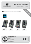
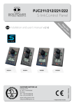
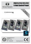
SIDE-POWER Thruster Systems v 1.3 is rd th a p bo ee n K al o u an Installation and user’s manual m ! SLEIPNER MOTOR AS P.O. Box 519 N-1612 Fredrikstad Norway Tel: +47 69 30 00 60 Fax: +47 69 30 00 70 w w w. s i d e - p o w e r. c o m s i d e p o w e r @ s l e i p n e r. n o © Sleipner Motor AS 2014 Made in Norway EN 8700 S-linkControl Panel Content Product Features................................................................................................... 3 S-Link overview .................................................................................................... 4 S-Link setup procedure ....................................................................................... 5 General use and alarm indication....................................................................... 6 Alarm codes.......................................................................................................... 7 DO NOT connect any other control equipment to the S-link controlled products except Side-Power original S-link products or via a Side-Power supplied interface product made for interfacing with other controls. Any attempt to directly control or at all connect into the S-link control system without the designated and approved interface, will render all warranties and responsibilities for the complete line of Side-Power products connected void and null. DECLARATION OF CONFORMITY We, Sleipner Motor AS P.O. Box 519 N-1612 Fredrikstad, Norway declare that this product with accompanying standard remote control systems complies with the essential health and safety requirements according to the Directive 89/336/EEC of 23 May 1989 amended by 92/31/EEC and 93/68/EEC. 2 Control Panel 8700 version 1.3- 2014 Product features 3 4 1 2 Ref: 1 2 3 4 PORT ON 2 OFF Pcs. 1x 1x 4x 4x Parts: Control panel Gasket Screws (A4) Corner clips STBD Installation: Find a comfortable position for the panel where it does not obstruct or are obstructed by other controls. Use the enclosed cut-out pattern to mark the area. Cut out the circular area as shown on pattern. If the front surface around your cut out is jaggered or chipped, use a sealant to assist the gasket. A B C D Put the gasket (2) in its designated track in the back face of the panel (1) Plug the S-link Spur cable into the connector at the rear of panel. Twist the locking ring on the connector clockwise to secure connector. Put the panel (1) in place and screw in and tighten the four screws (3) Press gently each of the four corner clips (4) into their corner slot Important ! This panel will only work with Side-Power electric retractable thrusters with a S-link control system. This panel is waterproof from the front side when correctly installed. However, you must ensure that it can never be submerged in water as this might cause a short circuit and malfunction of the thruster system. Control Panel 8700 version 1.3- 2014 3 B S-Link Overview Retract panel 5A +12V red Power supply cable Battery black yellow 12V Manual main switch Main fuse T-connector T-connector T-connector Terminator 120 ohm + Terminator 120 ohm M - 8730 Foot Switches ( opt.) Actuator Controller 6 1242 Remote control (opt.) optional Retract thruster Setup with manual main switch Retract panel 5A +12V red Power supply Wiringcable Retract thruster W / manual main switch T-connector T-connector black yellow Battery Sleipner Motor AS P.O. Box 519 12V N-1612 Fredrikstad Norway Tel: +47 69 30 00 60 Draw no: Automatic Main Switch w/S-link T-connector Terminator 120 ohm Drawn: Terminator 120 ohm + M - 8730 Foot Switches ( opt.) Actuator Controller 6 1242 Remote control (opt.) optional Setup with automatic main switch 4 system schematics Control Panel 8700 S-link S-link control system is powered by a dedicated power cable con- Retract thruster N version 1.3- 2014 S-link koblingsskjema S-link systemeter strømforsynt via en dediker strømkabel som koble S-Link Setup Procedure To control a dual thruster setup on one S-link bus, the panels must be set up to control one thruster each. As factory default, the panel is setup to control the bow thruster. The panel controlling the stern thruster must be set up following the procedure described: 1 Disconnect all S-link equipment concerning the bow thruster (Panel, AMS, Thruster Control Box, Interface etc.) from the S-link bus, and keep all equipment concerning the stern thruster connected. 2. Make sure panel is turned OFF. 3. Press and hold ON button 2 and PORT button at the same time for approx. 3 seconds. The yellow status LED will blink and the red OR green LED turns on (factory default: GREEN - controlling bow thruster). 4. Press STARBOARD button to assign this panel and all connected devic es as STERN. RED status LED will light up to confirm setup as stern thruster. 5. Turn off panel, and reconnect all S-link equipment. The same procedure can be used to match all devices for a single thruster system bow or stern. Just follow steps 2,3,4 and 5. At step 4 press PORT button to assign all the devices connected as BOW. GREEN status LED will light up to comfirm setup as bow thruster. Control Panel 8700 version 1.3- 2014 5 General use and alarm indication PANEL ON: push both “ON” buttons simultaneously, thruster deploys. PANEL OFF: push “OFF” button, thruster retracts. Operate thruster by pushing red and green arrows. STATUS/ALARM LEDS: YELLOW LED solid light means panel is on. GREEN LED flashes during deploy phase, Solid GREEN LED indicates thruster deployed and ready to operate. RED LED flashes during retract phase, all LEDs out when panel/thruster is shut down. If something unexpected happens while deploying/retracting thruster, the LEDs will flash alarm codes according to form on next page. Note! THE MAIN SWITCH MUST BE TURNED OFF IMMEDIATELY WHEN AN IPC ERROR OCCURS TO PREVENT OVERHEATING OF THE MAIN THRUSTER RELAYS! THRUSTER WILL NOT RETRACT WHILE REVERSING AT “HIGH” SPEED. THIS WILL TRIGGER THE “RETRACT OPERATION OBSTRUCTED” ALARM. IF AN ALARM IS TRIGGERED, REDUCE SPEED AN PRESS BOTH “ON” BUTTONS SIMULTANEOUSLY BEFORE RETRYING “OFF” BUTTON 6 Control Panel 8700 version 1.3- 2014 Control Panel 8700 version 1.3- 2014 1 flash YELLOW & RED - Pause 2 flashes YELLOW & RED - Pause 3 flashes YELLOW & RED - Pause 1 flashes YELLOW, GREEN & RED Pause 2 flashes YELLOW, GREEN & RED Pause 3 flashes YELLOW, GREEN & RED Pause 4 flashes YELLOW, GREEN & RED Pause 1 2 3 1 3 Retracts Retracts Retracts Retracts Automatic Main Switch manual override Panel has no contact with thruster. Automatic Main Switch Power failure Automatic Main Switch fuse blown Retract operation obstructed Thruster IPC error Power failure, Actuator Thruster reaction None None None Aborts retract, deploys and retries to retract 3 times. If operation still is obstructed, retract stops on obstruction None Retracts System shuts down SR150000 solenoid output short Retracts circuit, port or starboard. SR150000 motor temp sensor fail Retracts SR150000 position sensor fail Thruster, low power Deploy operation obstructed Failure Thruster, overtemp C:\Users\olekr\AppData\Local\Microsoft\Windows\Temporary Internet Files\Content.Outlook\JZ2NO5R1\Panel 20.10.2014 alarms (3) 4 2 6 flashes YELLOW & GREEN - Pause 6 4 flashes YELLOW & GREEN - Pause 4 5 flashes YELLOW & GREEN - Pause 2 flashes YELLOW & GREEN - Pause 3 flashes YELLOW & GREEN - Pause 2 3 5 Panel alarm indication 1 flash YELLOW & GREEN - Pause LED 1 ALARM SPEC. RETRACT Side 1 av 1 Turn off panel. Check main switch, fuse, cable connections, cables. Retry. Pull up Automatic Main Switch Replace fuse on Automatic Main Switch. If new instalation, check if input and output is correct connected. Check power to Automatic Main Switch Turn off panel, charge batteries. Turn off panel. Go for lower speed/deeper water. Retry. Position sensor short or open circuit. Check wiring and connection. Check solenoid wiring and connection, and check if solenoid is shorted. Check motor temp sensor, wiring and connection. Turn off panel. Check actuator connections . Retry. Turn off panel - thruster must be serviced by authorized personel. Press both ON-buttons to deploy thruster. Turn Main-Switch off. Remove obstruction. User action Turn off panel, wait for 20 mins. Alarm Codes 7 Worldwide sales and service www.side-power.com SLEIPNER MOTOR AS P.O. Box 519 N-1612 Fredrikstad Norway Tel: +47 69 30 00 60 Fax:+47 69 30 00 70 www.side-power.com [email protected]


