1
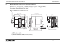
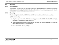
HARDWARE MANUAL FX2N-64DP-M Profibus-DP Master Block FX2N-64DP-M Profibus-DP Master Block Foreword • This manual contains text, diagrams and explanations which will guide the reader in the correct installation and operation of the FX2N-64DP-M Profibus-DP Master Block. It should be read and understood before attempting to install or use the unit. • Further information can be found in the FX2N Series Hardware Manual, FX Series Programming Manual ΙΙ, MELSEC ProfiMap Configuration System for Open Networks Software Manual and manual of Profibus-DP slave units. • If in doubt at any stage of the installation of FX2N-64DP-M Profibus-DP Master Block always consult a professional electrical engineer who is qualified and trained to the local and national standards which apply to the installation site. • If in doubt about the operation or use of FX2N-64DP-M Profibus-DP Master Block please consult the nearest Mitsubishi Electric distributor. • This manual is subject to change without notice. FX2N-64DP-M Profibus-DP Master Block FX2N-64DP-M Profibus-DP Master Block Manual number : JY992D82901 Hardware Manual Manual revision : D Date : March 2001 FX2N-64DP-M Profibus-DP Master Block ii FX2N-64DP-M Profibus-DP Master Block Guidelines for the Safety of the User and Protection of the FX2N-64DP-M Profibus-DP Master Block. This manual provides information for the use of the FX2N-64DP-M Profibus-DP Master Block. The manual has been written to be used by trained and competent personnel. The definition of such a person or persons is as follows: a) Any engineer who is responsible for the planning, design and construction of automatic equipment using the product associated with this manual, should be of a competent nature, trained and qualified to the local and national standards required to fulfill that role. These engineers should be fully aware of all aspects of safety with regards to automated equipment. b) Any commissioning or service engineer must be of a competent nature, trained and qualified to the local and national standards required to fulfill that job. These engineers should also be trained in the use and maintenance of the completed product. This includes being completely familiar with all associated documentation for said product. All maintenance should be carried out in accordance with established safety practices. c) All operators of the completed equipment should be trained to use that product in a safe and co-ordinated manner in compliance to established safety practices. The operators should also be familiar with documentation which is connected with the actual operation of the completed equipment. Note : The term ‘completed equipment’ refers to a third party constructed device which contains or uses the product associated with this manual. iii FX2N-64DP-M Profibus-DP Master Block Note’s on the Symbols Used in this Manual At various times through out this manual certain symbols will be used to highlight points of information which are intended to ensure the users personal safety and protect the integrity of equipment. Whenever any of the following symbols are encountered its associated note must be read and understood. Each of the symbols used will now be listed with a brief description of its meaning. Hardware Warnings 1) Indicates that the identified danger WILL cause physical and property damage. 2) Indicates that the identified danger could POSSIBLY cause physical and property damage. 3) Indicates a point of further interest or further explanation. Software Warnings 4) Indicates special care must be taken when using this element of software. 5) Indicates a special point which the user of the associate software element should be aware. 6) Indicates a point of interest or further explanation. iv FX2N-64DP-M Profibus-DP Master Block • Under no circumstances will Mitsubishi Electric be liable responsible for any consequential damage that may arise as a result of the installation or use of this equipment. • All examples and diagrams shown in this manual are intended only as an aid to understanding the text, not to guarantee operation. Mitsubishi Electric will accept no responsibility for actual use of the product based on these illustrative examples. • Owing to the very great variety in possible application of this equipment, you must satisfy yourself as to its suitability for your specific application. v FX2N-64DP-M Profibus-DP Master Block vi FX2N-64DP-M Profibus-DP Master Block Table of Contents Guideline ............................................................................................. iii 1. Introduction............................................................................................1-1 1.1 Features of the 64DP-M ...................................................................................... 1-1 1.2 External Dimensions and Each Part Name ......................................................... 1-2 1.2.1 Pin Configuration of Profibus-DP Communication Port ............................................. 1-5 1.3 System Configuration .......................................................................................... 1-6 1.3.1 Applicable Profibus-DP Network ............................................................................... 1-6 1.3.2 Applicable Programmable Controller......................................................................... 1-9 2. Wiring and Mounting .............................................................................2-1 2.1 Mounting .............................................................................................................. 2-2 2.1.1 Arrangements ............................................................................................................ 2-2 2.1.2 Mounting.................................................................................................................... 2-2 2.2 Wiring .................................................................................................................. 2-4 2.2.1 Wiring of Power Supply ............................................................................................. 2-4 2.2.2 Wiring of Profibus-DP ................................................................................................ 2-6 2.2.3 Terminating Resistor ................................................................................................. 2-7 vii FX2N-64DP-M Profibus-DP Master Block 3. Specifications ........................................................................................3-1 3.1 General Specifications......................................................................................... 3-1 3.2 Power Supply Specifications ............................................................................... 3-1 3.3 Performance Specifications ................................................................................. 3-2 4. Mode and Displayed Station Address ...................................................4-1 4.1 Mode.................................................................................................................... 4-1 4.1.1 Mode Setting Switch.................................................................................................. 4-2 4.2 Displayed Station Address .................................................................................. 4-3 5. Diagnostics............................................................................................5-1 5.1 Preliminary Checks.............................................................................................. 5-1 5.2 Check the Status of the LEDs for the 64DP-M .................................................... 5-2 5.3 Self Diagnostic of the 64DP-M ............................................................................ 5-6 Appndix A Further Information Manual List ............................................................... A-1 viii FX2N-64DP-M Profibus-DP Master Block 1. Introduction 1.1 Features of the 64DP-M Introduction 1 The FX2N-64DP-M Profibus-DP Master Block (hereafter called “64DP-M”) is a “Class 1” master for the Profibus-DP network (hereafter called “Profibus-DP”). The FX2N series programmable controller by connecting 64DP-M can read input data from the Profibus-DP slave (hereafter called “DP-slave”), and write output data to the DP-slave. • Controlled maximum slaves: A 64DP-M can control a maximum of 60 slaves using repeaters on the DP-network. For system configuration of the Profibus-DP, refer to section 1.3. • Configuration setting: Configuration of the 64DP-M can be set easily by MELSEC ProfiMap configuration software (V3.00 or more). For MELSEC ProfiMap configuration software (hereafter called “ProfiMap), refer to MELSEC ProfiMap Configuration System for Open Networks Software Manual. • Communication: The 64DP-M supports 9.6k, 19.2k, 93.75k, 187.5k, 500k, 1,500k, 3M, 6M and 12Mbps. The 64DP-M can be connected to a Profibus-DP by a standard 9-pin D-SUB connector and shielded twisted pair cable complying with EN50170. See chapter 2. • Global control: The 64DP-M supports Sync global control, Unsync global control, Freeze global control and Unfreeze global control. 1-1 FX2N-64DP-M Profibus-DP Master Block External Dimensions and Each Part Name Dimensions: mm (inches) MASS (Weight): Approx. 0.4kg (0.88 lbs) Accessory: Special block No. label g ) 5 (0 .2 0 ") S T N O . b ) M O D E i) F X b ) 0 O 1 P 2 T E O N L R M E S N L 2 N -6 4 D P -M IN E 1 S E T l) T IN E 2 T E S T B 6 S B 5 T B 4 B 3 N O . B 2 B 1 B 0 g ) h ) 9 5 .5 (3 .7 6 ") 1 0 2 (4 .0 2 ") N /R D K E N A D Y O M /T O M S E T P E R R U L T P O W E R P R O F IB U S -D P h ) T E S T B 6 B 5 B 4 B 3 B 2 B 1 B 0 f) R U S D T O R E F R P R R S F A R S -2 3 2 -C -6 4 D P -M P R O F IB U S -D P 2 N e ) M O D E 4 5 2 3 8 9 A 6 7 R S -2 3 2 -C F X P O W E R c ) F G b ) N /R D K E N A D Y O M /T O M S E T P E R R U L T 2 4 - R U S D T O R E F R P R R S F A j) k ) b ) 0 1 E F d ) 2 4 + a ) 8 7 (3 .4 3 ") 8 5 (3 .3 5 ") 5 (0 .2 0 ") c ) 5 (0 .2 0 ") 9 0 (3 .5 4 ") 5 (0 .2 0 ") Figure 1.1: External Dimensions B C D 1.2 Introduction 1 g ) 9 (0 .3 5 ") T o p c o v e r re m o v e d a) Extension cable b) Direct mounting hole (2-∅4.5 (0.18")) 1-2 b ) FX2N-64DP-M Profibus-DP Master Block Introduction 1 c) RS-232C port (9-pin D-SUB Connector: #4-40unc inch screw thread) The cable connecting between 64DP-M and personal computer is Blue ProfiCab cable. For Blue ProfiCab, refer to MELSEC ProfiMap Configuration System for Open Networks Software Manual. d) Status LEDs Table 1.1: Status LEDs LED Name Description RUN LED ON: During normal operation OFF: Error SD/RD LED Flashes during communication with slave on the Profibus network. The flashing interval is the time interval of the bus parameter’s Data Control Time. TOKEN LED ON when token is maintained. READY LED ON when the Profibus-DP network subscription preparation is completed and during subscription. FROM/TO LED ON when a FROM/TO instruction from the programmable controller is operating. PRM.SET LED ON (PARAMETER SET) when in the parameter setting mode. When flashing during operation, the parameter is not written. RSP ERR LED ON when a communication error occurs. FAULT LED ON when an error occurs. e) POWER LED: ON when 24V DC power is supplied form the external power supply or FX2N series PLC. 1-3 FX2N-64DP-M Profibus-DP Master Block Introduction 1 f) TEST LED and STATION LED Table 1.2: TEST LED and STATION LED LED Name Description TEST LED ON when self-diagnosis mode is executing. STATION LED Displays the station address (Binary) during normal operation. Displays the test type during self-diagnosis mode. (B0 ~ B6) g) Hook for mounting DIN rail h) Profibus-DP communication port (9-pin D-SUB Connector: #4-40unc inch screw thread) i) Groove for mounting DIN rail (DIN 46277<DIN rail width: 35mm (1.38")>) j) DC power supply terminals (screws terminal: M3 ) k) Mode setting switch (Default setting: “0”) For mode, refer to Chapter 4. Table 1.3: Mode Switch Switch No. Mode 0 ONLINE1 (Normal service mode) 1 PRM SET (Parameter setting mode) 2 TEST (Self diagnostic mode) E ONLINE2 (Extended service mode) 3 ~ D, F Cannot use l) Extension port 1-4 FX2N-64DP-M Profibus-DP Master Block Pin Configuration of Profibus-DP Communication Port The connector is a 9-pin D-SUB (#4-40unc inch screw thread) type, the pin configuration is shown below. Figure 1.2: Pin Layout of Profibus-DP Communication Port 5 Table 1.4: Profibus-DP Communication Port Pin Configuration Meaning RXD/TXD-P Receive/transmit-Data-P 5 DGND Data Ground 6 VP Voltage-Plus 8 RXD/TXD-N Receive/transmit-Data-N 1, 2, 4, 7, 9 7 3 8 3 2 Signal Name 1 4 9 Pin No. 6 1.2.1 Introduction 1 Assigned Not assigned NC Pin not assigned 1-5 FX2N-64DP-M Profibus-DP Master Block 1.3 System Configuration 1.3.1 Applicable Profibus-DP Network Introduction 1 Note; • The maximum number of slaves that can be connected to a 64DP-M is 60. • Number that can be connected for 1 segment Masters + slaves + repeaters ≤ 32 units • Number of units that can be connected to the entire network using repeaters. Masters + slaves ≤ 126 units • Communications can be conducted via a maximum of 3 repeaters from an arbitrary master or arbitrary slave to an arbitrary master or arbitrary slave. However, the whole network can contain more than 3 repeaters. (See note above.) 1-6 FX2N-64DP-M Profibus-DP Master Block Introduction 1 Note; When using a slave with expansion diagnostic information of more than 32 bytes, the network will be limited. Maximum expansion diagnostic information data length is the smaller of the value obtained from a slave address by the following equation or 244 bytes. Maximum expansion diagnostic information data length (bytes) = [12600 ÷ N*1 - 10] or [244] *1 The value of N is the smaller of the value obtained by the following equation or 300. N = [(Max. slave address value - Min. slave address value + 1) × 5] or [300] Note: It is not possible to communicate normally with the slave when the maximum diagnosis information data length (Max_Diag_Data_Len) has been decided by the slave’s GSD file is larger than the value obtained by the above expression. In this case, please try the following things. 1) Make the slave address consecutive number if possible. 2) Change setting so that this value may become small if the maximum diagnosis information data length on the slave side can be set. 3) Reduce connected number of the slave. 1-7 FX2N-64DP-M Profibus-DP Master Block Introduction 1 Figure 1.3: Example System Configuration <Connecting 1 Master (class 1) on the Profibus-DP Network> FX2N Series FX2N-64DP-M (Master of Class 1) Configuration Software (ProfiMap) Terminating resistor Terminating resistor Profibus-DP Network Slave No.1 Slave No.2 Slave No.3 Slave No.29 Slave No.30 Slave No.31 *1 In this system configuration, this 64DP-M can connect maximum 31 slaves. As the total units (masters + slaves + repeaters) is 32 units when DP-network is 1 segment. 1-8 FX2N-64DP-M Profibus-DP Master Block 1.3.2 Introduction 1 Applicable Programmable Controller For setting up a system, the 64DP-M can be connected directly to the FX 2N series programmable controller’s extension port, or to any other extension unit / block’s right side extension port. The 64DP-M occupies 8 points of I/O on the FX2N ’s expansion bus. The 8 points can be allocated from either inputs or outputs. The maximum I/O for a FX2N system is 256 I/O. Table 1.5: Applicable Programmable Controller Programmable Controller Type FX2N series Version From first product (All versions) 1-9 FX2N-64DP-M Profibus-DP Master Block Introduction 1 MENO 1-10 FX2N-64DP-M Profibus-DP Master Block 2. Wiring and Mounting 2 Wiring and Mounting Caution 1) Do not lay signal cable near to high voltage power cable or house them in the same trunking duct. Effects of noise or surge induction may occur. Keep signal cables a safe distance of more than 100 mm (3.94") from these power cables. 2) Ground the shield wire or the shield of a shielded cable at one point on the programmable controller. Do not, however, ground to the same point as high voltage lines. 3) Terminal screws of the 64DP-M are M3 (0.12"), therefore crimp style terminals (see drawing) suitable for use with these screws should be fitted to the cable for wiring. Figure 2.1: Crimp Terminals 6.2 mm (0.24" ) or less For M3 (0.12") For M3 (0.12") 6.2 mm (0.24") or less 4) The terminal tightening torque is 0.5 ~ 0.8 Nm. Tighten securely to avoid malfunction. 5) Cut off all phases of power source before installing / removing or performing wiring work on the master in order to avoid electric shock or damage of product. 6) Replace the provided terminal cover before supplying power and operating the unit after installation or wiring work, in order to avoid electric shock. 2-1 FX2N-64DP-M Profibus-DP Master Block 2.1 Mounting 2.1.1 Arrangements Wiring and Mounting 2 The 64DP-M connects on the right side of an FX2N series main unit or extension unit/block (including special function blocks). For further information of mounting arrangements, refer to the hardware manual of the associated main unit. 2.1.2 Mounting The mounting method of the 64DP-M can be DIN rail mounting or direct wall mounting. 1) DIN rail mounting a) Align the upper side of the DIN rail mounting groove of the 64DP-M with a DIN rail*1 (), and push it on the rail(). See Figure 2.2. b) When removing the 64DP-M from the rail, the hook for DIN rail is pulled (), and the 64DP-M is removed (). See Figure 2.2. *1 Uses DIN 46277 <35mm (1.38")> 2-2 FX2N-64DP-M Profibus-DP Master Block Wiring and Mounting 2 Figure 2.2: Attach to DIN Rail and Remove from DIN Rail 2) Direct mounting to back walls The 64DP-M can be mounted with an M4 screws by using the direct mounting holes. An interval space between each unit of 1 ~ 2 mm is necessary. 2-3 FX2N-64DP-M Profibus-DP Master Block 2.2 Wiring 2.2.1 Wiring of Power Supply Wiring and Mounting 2 The 64DP-M needs power to be supplied from an FX2N series PLC or external power supply. Caution When the 64DP-M is supplied with 24V DC from external power supply, it needs to be started up at the same time as the FX2N series PLC. If this external power supply is late to start up, FX2N series PLC could be down. 2-4 FX2N-64DP-M Profibus-DP Master Block Wiring and Mounting 2 Figure 2.3: Power Supply From PLC 24V 0V +24V FX2N Series PLC -24V FX2N-64DP-M Figure 2.4: Power Supply From External Power Supply External power supply 0V 24V 0V FX2N Series PLC 24V +24V -24V FX2N-64DP-M 2-5 FX2N-64DP-M Profibus-DP Master Block 2.2.2 Wiring and Mounting 2 Wiring of Profibus-DP To connect the 64DP-M to a Profibus-DP network use only the Profibus connectors and shielded twisted-pair cable complying with EN50170. For Profibus connectors see the Profibus connector’s manual. Figure 2.5: Wiring For Profibus connection, refer to Figure 2.6. Shielded twisted-pair cable complying with EN50170 to Profibus-DP network Grounding plate Grounding resistance of 100 Ω or less (Class D) External power supply or the service power supply of PLC FG +24 -24 FX2N-64DP-M Profibus-DP Master Block RS-232C port for connecting configuration software (ProfiMap) For noise prevention please attach at least 50 mm (1.97") of the twisted-pair cable along the grounding plate to which the ground terminal is connected. 2-6 FX2N-64DP-M Profibus-DP Master Block Wiring and Mounting 2 Figure 2.6: Profibus Connection Shielded twisted-pair cable of Profibus-DP network FX2N-64DP-M Profibus-DP Master Block 2.2.3 Terminating Resistor The units at each end of the Profibus-DP network must have a terminating resistor. This will either be in the master or slave unit or in the Profibus connector. However, the 64DP-M does not have a terminating resistance built-in. 2-7 FX2N-64DP-M Profibus-DP Master Block Wiring and Mounting 2 MEMO 2-8 FX2N-64DP-M Profibus-DP Master Block 3. Specifications 3.1 General Specifications Specifications 3 Table 3.1: General Specifications Items Description General specifications excluding Same as those of the main unit Dielectric Withstand Voltage 3.2 Dielectric Withstand Voltage 500 V AC > 1 min., tested between DC power supply terminals and earth Complies With UL508 Power Supply Specifications Table 3.2: Power Supply Specifications Items Description External Power Supply 250 mA at 24 V DC Internal Power Supply 30 mA at 5 V DC supplied via extension cable 3-1 FX2N-64DP-M Profibus-DP Master Block 3.3 Specifications 3 Performance Specifications Table 3.3: Performance Specifications Item Specifications Transmission Type Bus network Unit type Profibus-DP master Class 1 Transmission Data (Maximum Exchanged Data Length) ONLINE1(Normal service mode): 32 bytes / slave ONLINE2(Extended service mode): 244 byte/slave Maximum Number of Repeaters 3 units / Network Maximum Number of Stations / Segment 32 stations (See Note 1) Maximum Number of Slaves / Master 60 slaves (See Note 1) Number Connection of Nodes (Number of Repeaters) 32, 62 (1), 92 (2), 126 (3) (See Note 1) 9.6k, 19.2k, 93.75k Supported Baud Rates 187.5k (bps) and 500k Bus Length 1.5 M 3M, 6M, 12M See Note 1 1,200 m (3,937') / segment 1,000 m (3,281') / segment 400 m (1,312') / segment See Note 2 200 m (656') / segment 100 m (328') / segment 3-2 FX2N-64DP-M Profibus-DP Master Block Specifications 3 Table 3.3: Performance Specifications Item PNO ID Connector Specifications F264 H RS-232C Port for download configuration (9 pin D-SUB Connector: #4-40unc inch screw thread) Profibus-DP Network Port for Profibus-DP network (9 pin D-SUB Connector: #4-40unc inch screw thread) Synchronization Synchronization, unsynchronization, freeze and unfreeze modes shall be supported. Terminal Resistor Not built in. Number of occupied I/O points 8 points taken from the programmable controller extension bus (can be either input or output) Applicable Programmable Controller FX2N Series 3-3 FX2N-64DP-M Profibus-DP Master Block Specifications 3 Table 3.3: Performance Specifications Item LED indicators LED indicators Specifications POWER LED ON when 24V DC power is supplied form the PLC or external power supply. RUN LED ON: During normal operation OFF: Error SD / RD LED Flashes during communication with slave on the Profibus network. The flashing interval is the time interval of the bus parameter’s Data Control Time. TOKEN LED ON when token is maintained. READY LED ON when the Profibus-DP network subscription preparation is completed and during subscription. FROM/TO LED ON when a FROM/TO instruction from the programmable controller is operating. PRM.SET LED ON (PARAMETER SET) when in the parameter setting mode. When flashing during normal operation, the parameter is not written. RSP ERR LED ON when a communication error occurs. FAULT LED ON when an error occurs. TEST LED ON when self-diagnosis is executing. STATION LED Displays the station address during normal operation.(Binary) Displays the test type during a self-diagnosis. (B0 to B6) 3-4 FX2N-64DP-M Profibus-DP Master Block Specifications 3 Note 1; When using a slave with expansion diagnostic information of more than 32 bytes, the network will be limited. Maximum expansion diagnostic information data length is the smaller of the value obtained from a slave address by the following equation or 244 bytes. Maximum expansion diagnostic information data length (bytes) = [12600 ÷ N*1 - 10] or [244] *1 The value of N is the smaller of the value obtained by the following equation or 300. N = [(Max. slave address value - Min. slave address value + 1) × 5] or [300] It is not possible to communicate normally with the slave when the maximum diagnosis information data length (Max_Diag_Data_Len) has been decided by the slave’s GSD file is larger than the value obtained by the above expression. In this case, please try the following things. 1) Make the slave address consecutive number if possible. 2) Change setting so that this value may become small if the maximum diagnosis information data length on the slave side can be set. 3) Reduce connected number of the slave. 3-5 FX2N-64DP-M Profibus-DP Master Block Specifications 3 Note 2; Length that the bus can be expanded by using repeaters. Maximum Bus Length = (“Number of repeaters” + 1) × “Bus Length / segment” Table 3.4: Maximum Bus Length and Baud Rate Baud Rate (bps) Maximum Bus Length No repeater 1 repeater 2 repeaters 3 repeaters 9.6k, 19.2k, 93.75k 1,200 m (3,937') 2,400 m (7,874') 3,600 m (11,811') 4,800 m (15,748') 187.5k 1,000 m (3,281') 2,000 m (6,562') 3,000 (9,843') 4,000 m (13,123') 500k 400 m (1,312') 800 m (2,625') 1,200 m (3,937') 1,600 m (5,249') 1.5 M 200 m (656') 400 m (1,312') 600 m (1,969') 800 m (2,625') 3M, 6M, 12M 100 m (328') 200 m (656') 300 m (984') 400 m (1,312') 3-6 FX2N-64DP-M Profibus-DP Master Block Mode and Displayed Station Address 4 4. Mode and Displayed Station Address 4.1 Mode The 64DP-M has 4 modes, decided by the mode setting switch. For setting instructions, refer to subsection 4.1.2. Table 4.1: Mode Mode ONLINE 1 (Normal service mode) Description 64DP-M can exchange 32 bytes/slave. ONLINE 2 (Extended service mode) 64DP-M can exchange 244 byte/slave. PRE SET (Parameter Setting mode) This mode is used for setting the parameter. TEST (Self Diagnostic mode) This mode is used for checking hardware of 64DP-M. For self test, refer to subsection 5.3. 4-1 FX2N-64DP-M Profibus-DP Master Block Mode Setting Switch The mode is decided by the mode setting switch. Default setting is “0” (Online 1 mode). Caution When changing the Mode, the power supply of the PLC and 64DP-M should be OFF. Figure 4.1: Mode Switch 0 1 E F 0 1 E F 0 1 E F C D AB C D AB 0 1 E F C D AB P R E S E T ( P a r a m e te r S e ttin g M o d e ) 4 5 6 23 T E S T ( S e lf D ia g n o s tic M o d e ) Table 4.2: Mode Switch Mode Switch Positions Mode 0 ONLINE 1 (Normal Service mode) 1 PRE SET (Parameter Setting mode) 2 TEST (Self Diagnostic mode) E ONLINE 2 (Extended Service mode) 3 ~ D, F 7 8 9 O N L IN E 2 ( E x te n d e d S e r v ic e M o d e ) 7 8 9 O N L IN E 1 ( N o r m a l S e r v ic e M o d e ) 4 5 6 23 7 8 9 4 5 6 23 7 8 9 4 5 6 23 C D AB 4.1.1 Mode and Displayed Station Address 4 Cannot use 4-2 FX2N-64DP-M Profibus-DP Master Block 4.2 Mode and Displayed Station Address 4 Displayed Station Address The station address set by parameter is displayed by the STATION LEDs when 64DP-M is in ONLINE 1 mode. The station address is displayed by the STATION LED (B0-B6) in binary. The parameter is set by configuration software (ProfiMap). For the ProfiMap configuration software, please see the MELSEC ProfiMap Configuration System for Open Networks Software Manual. Example When station address is 10, display is as follows. Figure 4.2: Example Displayed Station Address TEST 64 B6 32 B5 16 B4 8 B3 4 B2 2 B1 1 B0 ST NO : LED is not lit. : LED is lit. 4-3 FX2N-64DP-M Profibus-DP Master Block Mode and Displayed Station Address 4 MEMO 4-4 FX2N-64DP-M Profibus-DP Master Block 5. Diagnostics 5 Diagnostics If the 64DP-M does not see to operate normally, check the following items. 5.1 Preliminary Checks 1) Check “POWER LED” If “POWER LED” is OFF, check the wiring of the 24V DC power supply, and check whether the 24V DC voltage source capacity is sufficient. 2) Check “RUN LED” If “RUN LED” is OFF, check status of the Exchange Start Request (BFM #2 Bit0). If this bit is OFF, turns this bit to ON. 3) Check “FAULT LED” If “FAULT LED” is OFF, check the diagnostic information in the Communication Trouble Area (BFM #2140 ~ #2179). For diagnostic information, refer to section 4.12. 4) Check the wiring and connection for the Profibus-DP If the wiring and connection for the Profibus-DP is incorrect, correct wiring and connection. 5) Check the system configuration and parameter of the 64DP-M for the Profibus-DP If the system configuration of Profibus-DP is not corresponding to parameter of the 64DP-M, match them. 6) Check the error of the PLC. If the FROM/TO instruction error occurs at this instruction for the 64DP-M in the PLC, operate correctly this instruction. 5-1 FX2N-64DP-M Profibus-DP Master Block 5.2 Diagnostics 5 Check the Status of the LEDs for the 64DP-M 1) POWER LED check Table 5.1: POWER LED Check State Description Lit The 24V DC power supply (PLC or external power supply) is correctly supplied. Unlit Check wiring of power supply, and check whether the 24V DC voltage source capacity of 24V DC power supply. 2) RUN LED check Table 5.2: RUN LED Check State Description Lit Normal Operation Unlit The watchdog timer timed out. Please contact a service representative. 5-2 FX2N-64DP-M Profibus-DP Master Block Diagnostics 5 3) SD/RD LED check Table 5.3: SD/RD LED Check State Description Lit If 64DP-M is the exchange start processing or exchange stop processing status, this state of LED is normal operation. However, when 64DP-M exchange to slave(s), check parameter setting of slave in 64DP-M. Flashing 64DP-M exchanges data to the slave(s). Unlit 64DP-M does not exchanges data to the slave(s). Check correctly state of the Exchange start end flag (BFM #0 bit 0). 4) TOKEN LED check Table 5.4: Token LED Check State Description Lit 64DP-M is in operation mode 0 or E. Flashing 64DP-M is in operation mode 0 or E with a multi master configuration. Unlit 64DP-M is in not operation mode 0 or E. Check mode switch, wiring, address setting about duplicate address, and if the HSA exceeds the network maximum station Number. 5-3 FX2N-64DP-M Profibus-DP Master Block Diagnostics 5 5) RADY LED check Table 5.5: RADY LED Check State Description Lit 64DP-M is in operation mode 0 or E. If it is not in these mode, please contact a service representative. Unlit 64DP-M is not operation mode 0 or E. If it is in these mode, please contact a service representative. 6) FROM/TO LED check Table 5.6: FROM/TO Check State Description Lit BFM in 64DP-M is accessed from PLC. Unlit BFM in 64DP-M is not accessed from PLC. Please check program about FROM/TO instruction. 7) PRM. SET LED check Table 5.7: PRM. SET LED Check State Description Lit 64DP-M is in operation mode 1. Flashing When this LED is flashing in operation mode 1, there is not parameter in 64DP-M. Please write parameter to 64DP-M. Unlit 64DP-M is in operation mode 0 or E. 5-4 FX2N-64DP-M Profibus-DP Master Block Diagnostics 5 8) RSP ERR LED check Table 5.8: RSP ERR Check State Description Lit 64DP-M is fault when exchange data to slave. Check diagnostic information. For diagnostic information, refer to section 4.12. Unlit 64DP-M is normal operation. 9) FAULT LED check Table 5.9: FAULT LED Check State Description Lit 1) When exchange start request flag (BFM #2 bit 0) is turned OFF to ON, check parameter about following points. • There is no active slave on the network. • There is slave station of same as master station address. 2) In other case, please contact a service representative. Unlit 64DP-M is normal operation. 5-5 FX2N-64DP-M Profibus-DP Master Block 5.3 Diagnostics 5 Self Diagnostic of the 64DP-M When setting the self diagnostic mode (The mode switch in position “2”.), TEST LED and ST NO LED will be lit as shown in the following table. When the test result is normal, these tests are repeated in order of a -e). If an error is detected, then the LED status at the time the error occurs for that test will be displayed. If error state is displayed, please contact a service representative. Table 5.10: Self Diagnostic Items LED State Description MPU test Timer test Interrupt test DRAM test Order TEST B6 B5 B4 B3 B2 B1 B0 During test a) l ¡ ¡ ¡ ¡ ¡ l l Error - l l ¡ ¡ ¡ ¡ l ¡ During test b) l ¡ ¡ ¡ ¡ l ¡ l Error - l l ¡ ¡ ¡ l ¡ ¡ During test c) l ¡ ¡ ¡ ¡ l l l Error - l l ¡ ¡ ¡ l l ¡ d) l ¡ ¡ ¡ l ¡ l l e) l ¡ ¡ ¡ l l ¡ l - l l ¡ ¡ l l l ¡ During test Error ¡: This LED is not lit. l: This LED is lit. 5-6 FX2N-64DP-M Profibus-DP Master Block Diagnostics 5 Figure 5.1: LED Location TEST B6 B5 B4 B3 ST NO B2 B1 B0 : LED is not lit. : LED is lit. 5-7 FX2N-64DP-M Profibus-DP Master Block Diagnostics 5 MEMO 5-8 FX2N-64DP-M Profibus-DP Master Block Appendix A Appendix A: Further Information Manual List Table A-1: Further Information Manual List Manual name Manual No. Description FX2N Series Programmable controllers Hardware Manual This manual contents expiantions for wiring, JY992D66301 installation and specification, etc. about FX2N Series programmable controller. FX0N-32NT-DP Profibus-DP Interface Unit User’s Manual This manual contents expiantions for wiring, JY992D61401 installation, specification and allocation BFM’s, etc. about FX0N-32NT-DP Profibus-DP Interface Unit. FX2N-32DP-IF Profibus-DP Interface Unit Hardware Manual This manual contents expiantions for wiring, installation and specification, etc. about FX2N-32DP-IF JY992D77101 Profibus-DP Interface Unit However, this hardware manual’s text is already contained in this user’s manual. FX2N-32DP-IF Profibus-DP Interface Unit User’s Manual This manual contents expiantions for wiring, installation, specification and parameter, etc. about JY992D79401 FX2N-32DP-IF Profibus-DP Interface Unit However, this hardware manual’s text is already contained in this user’s manual. A-1 FX2N-64DP-M Profibus-DP Master Block Table A-1: Further Information Manual List Manual name FX2N-64DP-M Profibus-DP Master Block User’s Manual MELSEC ProfiMap Configuration System for Open Networks Software Manual Manual No. Description This manual contents expiantions for wiring, installation, specification and allocation BFM’s, etc. JY992D88001 about FX2N-64DP-M Profibus-DP Master Block. However, this hardware manual’s text is already contained in this user’s manual. - This manual contents expiantions for MELSEC ProfiMap Configuration System for Open Networks Software. A-2 FX2N-64DP-M Profibus-DP Master Block MEMO A-3 FX2N-64DP-M Profibus-DP Master Block MEMO A-4 HARDWARE MANUAL FX2N-64DP-M Profibus-DP Master Block HEAD OFFICE: MITSUBISHI DENKI BLDG MARUNOUCHI TOKYO 100-8310 TELEX: J24532 CABLE MELCO TOKYO HIMEJI WORKS: 840, CHIYODA CHO, HIMEJI, JAPAN JY992D82901D (MEE) Effective MAR. 2001 Specification are subject to change without notice.