1
USER’S MANUAL
FX0N-32NT-DP Profibus-DP Interface Unit
FX0N-32NT-DP Profibus-DP Interface Unit
Foreword
•
This manual contains text, diagrams and explanations which will guide the reader in the correct installation
and operation of the FX0N-32NT-DP Profibus-DP Interface Unit. It should be read and understood before
attempting to install or use the unit.
•
Further information can be found in the Hardware Manual of the PLC, Programming Manual of the PLC,
MELSOFT GX Configurator-DP Configuration System for Open Networks Software Manual and the manual
of the Profibus-DP master units.
•
If in doubt at any stage of the installation of FX0N-32NT-DP Profibus-DP Interface Unit always consult a professional electrical engineer who is qualified and trained to the local and national standards which apply to
the installation site.
•
If in doubt about the operation or use of FX0N-32NT-DP Profibus-DP Interface Unit please consult your local
Mitsubishi Electric representative.
•
This manual is subject to change without notice.
FX0N-32NT-DP Profibus-DP Interface Unit
FX0N-32NT-DP Profibus-DP
Interface Unit
Manual number : JY992D61401
User’s Manual
Manual revision : H
Date
: April 2015
This manual confers no industrial property rights or any rights of any other kind, nor does it confer any
patent licenses. Mitsubishi Electric Corporation cannot be held responsible for any problems involving
industrial property rights which may occur as a result of using the contents noted in this manual.
© 1997 MITSUBISHI ELECTRIC CORPORATION
i
FX0N-32NT-DP Profibus-DP Interface Unit
ii
FX0N-32NT-DP Profibus-DP Interface Unit
Guidelines for the Safety of the User and Protection of the FX0N-32NT-DP
Profibus-DP Interface Unit.
This manual provides information for the use of the FX0N-32NT-DP Profibus-DP Interface Unit.
The manual has been written to be used by trained and competent personnel. The definition of
such a person or persons is as follows:
a) Any engineer who is responsible for the planning, design and construction of automatic
equipment using the product associated with this manual, should be of a competent
nature, trained and qualified to the local and national standards required to fulfill that
role. These engineers should be fully aware of all aspects of safety with regards to
automated equipment.
b) Any commissioning or service engineer must be of a competent nature, trained and
qualified to the local and national standards required to fulfill that job. These engineers
should also be trained in the use and maintenance of the completed product. This
includes being completely familiar with all associated documentation for said product. All
maintenance should be carried out in accordance with established safety practices.
c) All operators of the completed equipment should be trained to use that product in a safe
and coordinated manner in compliance to established safety practices. The operators
should also be familiar with documentation which is connected with the actual operation
of the completed equipment.
Note : The term ‘completed equipment’ refers to a third party constructed device which
contains or uses the product associated with this manual.
iii
FX0N-32NT-DP Profibus-DP Interface Unit
Note’s on the Symbols Used in this Manual
At various times through out this manual certain symbols will be used to highlight points of
information which are intended to ensure the users personal safety and protect the integrity of
equipment. Whenever any of the following symbols are encountered its associated note must
be read and understood. Each of the symbols used will now be listed with a brief description of
its meaning.
Hardware Warnings
1) Indicates that the identified danger WILL cause physical and property damage.
2) Indicates that the identified danger could POSSIBLY cause physical and property
damage.
3) Indicates a point of further interest or further explanation.
Software Warnings
4) Indicates special care must be taken when using this element of software.
5) Indicates a special point which the user of the associate software element should
be aware.
6) Indicates a point of interest or further explanation.
iv
FX0N-32NT-DP Profibus-DP Interface Unit
• Under no circumstances will Mitsubishi Electric be liable or responsible for any
consequential damage that may arise as a result of the installation or use of this equipment.
• All examples and diagrams shown in this manual are intended only as an aid to
understanding the text, not to guarantee operation. Mitsubishi Electric will accept no
responsibility for actual use of the product based on these illustrative examples.
• Owing to the very great variety in possible application of this equipment, you must satisfy
yourself as to its suitability for your specific application.
Registration
The company name and the product name to be described in this manual are the registered
trademarks or trademarks of each company.
v
FX0N-32NT-DP Profibus-DP Interface Unit
vi
FX0N-32NT-DP Profibus-DP Interface Unit
Table of Contents
Guideline ............................................................................................. iii
1. Introduction............................................................................................1-1
1.1 Features of the 32NT-DP .................................................................................... 1-1
1.2 External Dimensions and Each Part Name ......................................................... 1-2
1.2.1 Pin Configuration of Profibus-DP Connector ............................................................. 1-4
1.3 System Configuration .......................................................................................... 1-5
1.4 Applicable PLC .................................................................................................... 1-6
2. Wiring and Mounting .............................................................................2-1
2.1 Mounting .............................................................................................................. 2-2
2.1.1 Arrangements ............................................................................................................ 2-2
2.1.2 Mounting.................................................................................................................... 2-2
2.2 Wiring .................................................................................................................. 2-4
2.2.1
2.2.2
2.2.3
2.2.4
EC and EMC Conformity ........................................................................................... 2-4
Power Supply Wiring ................................................................................................. 2-5
Profibus-DP Wiring .................................................................................................... 2-7
Terminating Resistor ................................................................................................. 2-8
3. Specifications ........................................................................................3-1
3.1 General Specifications......................................................................................... 3-1
3.2 Power Supply Specifications ............................................................................... 3-1
3.3 Performance Specifications ................................................................................. 3-2
vii
FX0N-32NT-DP Profibus-DP Interface Unit
4. Buffer Memories (BFMs) Allocation.......................................................4-1
4.1
4.2
4.3
4.4
4.5
Buffer Memories (BFM) Lists ............................................................................... 4-2
Received Output Data, Input Data to Send (BFM #0 ~ #19) <Read/Write> ........ 4-3
Data Exchange Status Bit (BFM #20) <Read Only> ........................................... 4-4
Swap Byte Order (BFM #21) <Read/Write> ........................................................ 4-4
Length of Sent Data (BFM #22), Length of Received Data (BFM #23)
<Read Only> ....................................................................................................... 4-4
4.6 Baud Rate (BFM #24) <Read Only> ................................................................... 4-5
4.7 Communication Status (BFM #25) <Read Only> ................................................ 4-6
4.7.1 Global Control Command .......................................................................................... 4-8
4.8
4.9
4.10
4.11
PROFIBUS Module ID (BFM #26) <Read Only>................................................. 4-9
Slave Address (BFM #27) <Read/Write> ............................................................ 4-9
User Diagnostics (BFM #28) <Read/Write> ...................................................... 4-10
Error Status (BFM #29) (Read Only) ................................................................. 4-11
4.11.1
4.11.2
4.11.3
4.11.4
4.11.5
4.11.6
4.11.7
4.11.8
General Error (BFM #29 Bit 0) ................................................................................ 4-12
External 24V Power Error (BFM #29 Bit 2).............................................................. 4-12
Hardware Error (BFM #29 Bit 3).............................................................................. 4-12
EEPROM Error (BFM #29 Bit 4).............................................................................. 4-12
FROM/TO Watchdog Timer (BFM #29 Bit 7) .......................................................... 4-13
Configuration Error (BFM #29 Bit 10) ...................................................................... 4-13
Parameter Error (BFM #29 Bit 11) .......................................................................... 4-13
Slave Address Change Error (BFM #29 Bit 12)....................................................... 4-13
4.12 Model identification code (BFM #30) <read only> ............................................. 4-14
viii
FX0N-32NT-DP Profibus-DP Interface Unit
5. Setting Operation ..................................................................................5-1
5.1 Installing 32NT-DP Parameters in the DP-master ............................................... 5-1
5.1.1 DP-slave Address Setting in the DP-master.............................................................. 5-1
5.1.2 Setting the Number and Format of Input and Output Words in the DP-master ......... 5-2
5.2 Setting Slave Address in the 32NT-DP ............................................................... 5-3
6. Example Program..................................................................................6-1
7. Diagnostics............................................................................................7-1
7.1 Preliminary Checks.............................................................................................. 7-1
7.2 LED Check .......................................................................................................... 7-2
7.3 Check BFM #29 error status of the 32NT-DP...................................................... 7-3
Appendix A:
Further Information Manual List ............................................................... A-1
ix
FX0N-32NT-DP Profibus-DP Interface Unit
x
FX0N-32NT-DP Profibus-DP Interface Unit
1.
Introduction 1
Introduction
This FX0N-32NT-DP Profibus-DP Interface Unit (called “32NT-DP” hereinafter) can be used as
a slave module to connect an FX0N, FX1N, FX2N or FX2NC*1 series programmable controllers
(called “PLC” hereinafter) to an existing Profibus-DP network.
The 32NT-DP provides an intelligent slave function for decentralized control applications which
need to exchange data with Profibus-DP master CPUs (called “DP-master” hereinafter).
*1 When using an FX2NC series PLC, an FX2NC-CNV-IF is required.
1.1
Features of the 32NT-DP
By using the 32NT-DP the PLC can exchange data with any DP-master.
• The default settings allow to send 16 words and to receive 16 words of data in one
communication cycle. These values can be adjusted between four word and 20 words of
sent and received data.
• The communication between the PLC main unit and the internal buffer memory of 32NT-DP
is handled by FROM/TO instructions.
• The 32NT-DP occupies 8 I/O points on the PLC’s expansion bus. The 8 points can be
allocated from either inputs or outputs.
• The 32NT-DP can be connected to a Profibus-DP network by a standard 9-pin D-SUB
connector and a shielded twisted pair cable complying with EN50170. Optional glassfiber
adapters are supported by the 32NT-DP and are available from other vendors.
1-1
FX0N-32NT-DP Profibus-DP Interface Unit
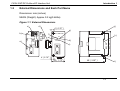
External Dimensions and Each Part Name
Dimensions: mm (inches)
MASS (Weight): Approx.0.3 kg(0.66lbs)
Figure 1.1: External Dimensions
c )
d )
2 4 G
F G
a )
F X
0 N
2 4 G
2 4 + F G
2 4 +
b )
4 ( 0 .1 6 " )
f)
e )
F X
0 N
P O W E R
B F
-3 2 N T
-D P
j)
g )
-3 2 N T -D P
D C
k )
R U N
D IA
h )
8 0 ( 3 .2 " )
9 0 ( 3 .6 " )
1.2
Introduction 1
i)
4 ( 0 .1 6 " )
4 3 ( 1 .7 2 " )
8 6 ( 3 .3 8 " )
l)
1-2
FX0N-32NT-DP Profibus-DP Interface Unit
Introduction 1
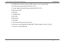
a) Profibus-DP connector (9-pin D-SUB: #4-40 inc. inch screw thread)
b) FG terminal (screws terminal: M3.5 (0.14"))
c) Power supply terminals (screws terminal: M3.5 (0.14"))
d) Extension cable
e) BF LED
f) POWER LED
g) DC LED
h) RUN LED
i) DIA LED
j) Direct mounting hole (2-φ4.5 (0.18"))
k) Groove for mounting DIN rail (DIN 46277 <DIN rail width: 35 mm (1.38")>)
l) Hook for mounting DIN rail
1-3
FX0N-32NT-DP Profibus-DP Interface Unit
Pin Configuration of Profibus-DP Connector
The connector is a 9-pin D-SUB (#4-40 inc. inch screw thread) type, and the pin configuration
is shown below.
Figure 1.2: Pin Layout of Profibus-DP Connector
5
Table 1.1: Profibus-DP Connector Pin
Configuration
9
Pin No.
2
7
3
8
4
3
Assigned
Not assigned
1
Signal
Meaning
RXD/TXD-P Receive/Transmit-Data-P
4
RTS
5
DGND
Data Ground
6
VP
Voltage-Plus
8
6
1.2.1
Introduction 1
1,2,7,9
Request to send
RXD/TXD-N Receive/Transmit-Data-N
NC
Pin not assigned
1-4
FX0N-32NT-DP Profibus-DP Interface Unit
1.3
Introduction 1
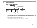
System Configuration
Figure 1.3: System Configuration
DP-master
Slave or
master*1
PLC*2
Profibus-DP network
PLC*2
Slave or
master*1
FX0N-32NT-DP
*1 The units at each end of the Profibus-DP network must have a terminating resistor. This
will either be in the master or slave unit or in the DP connector.
*2 PLC is FX0N, FX1N, FX2N or FX2NC series PLC.
When using an FX2NC series PLC, an FX2NC-CNV-IF is required.
1-5
FX0N-32NT-DP Profibus-DP Interface Unit
1.4
Introduction 1
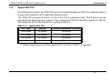
Applicable PLC
For setting up a system, the 32NT-DP can be connected directly to the PLC’s extension port or
to any other extension unit’s right side extension port.
The 32NT-DP occupies 8 points of I/O on the PLC’s expansion bus. The 8 points can be
allocated from either inputs or outputs. The maximum I/O for the FX0N/FX1N system is 128 I/O.
The maximum I/O for the FX2N/FX2NC system is 256 I/O.
Table 1.2: Applicable PLC
PLC Type
Version
Controlled maximum I/O points
FX0N Series
All version
128 points
FX1N Series
All version
128 points
FX2N Series
All version
256 points
FX2NC Series*1
All version
256 points
*1 When connecting to an FX2NC series PLC, an FX2NC-CNV-IF is required.
1-6
FX0N-32NT-DP Profibus-DP Interface Unit
2.
Wiring and Mounting 2
Wiring and Mounting
Caution
1) Do not lay signal cable near to high voltage power cable or house them in the same
trunking duct. Effects of noise or surge induction may occur. Keep signal cables a safe
distance of more than 100 mm (3.94") from these power cables.
2) Ground the shield wire or the shield of a shielded cable at one point on the programmable
controller. Do not, however, ground at the same point as high voltage lines.
3) The terminal screws of the 32NT-DP are M3.5 (0.14"), therefore the crimp style terminal
(see drawing) suitable for use with these screws should be fitted to the cable for wiring.
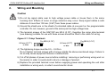
Figure 2.1: Crimp Terminals
6.8 mm (0.27" )
or less
For M3.5 (0.14")
For M3.5 (0.14")
6.8 mm (0.27")
or less
4) The tightening torque must be 0.5 ~ 0.8 Nxm.
Do not tighten terminal screws with a torque outside the above-mentioned range. Failure to
do so may cause equipment failures or malfunctions.
5) Cut off all phases of power source before installing / removing or performing wiring work on
the master in order to avoid electric shock or damage of product.
6) Replace the provided terminal cover before supplying power and operating the unit after
installation or wiring work, in order to avoid electric shock.
2-1
FX0N-32NT-DP Profibus-DP Interface Unit
2.1
Mounting
2.1.1
Arrangements
Wiring and Mounting 2
The 32NT-DP connects on the right side of the connected FX0N, FX1N, FX2N or FX2NC*1 series
main unit or extension unit/block (including special function blocks). For further information of
mounting arrangements, refer to the hardware manual of the connected main unit.
*1 When connecting to an FX2NC series PLC, an FX2NC-CNV-IF is required.
2.1.2
Mounting
The mounting method of the 32NT-DP can be DIN rail mounting or direct wall mounting.
1) DIN rail mounting
a) Align the upper side of the DIN rail mounting groove of the 32NT-DP with a DIN rail*1
(c), and push it on the DIN rail(d). See Figure 2.2.
b) When removing the 32NT-DP from the DIN rail, the hook for DIN rail is pulled (e), and
the 32NT-DP is removed (f). See Figure 2.2.
*1 Uses DIN 46277 <35mm (1.38")>
2-2
FX0N-32NT-DP Profibus-DP Interface Unit
Wiring and Mounting 2
Figure 2.2: Attach to DIN Rail and Remove from DIN Rail
2) Direct mounting to back walls
The 32NT-DP can be mounted with the M4 screw by using the direct mounting hole.
However, an interval space between each unit of 1 ~ 2 mm is necessary.
2-3
FX0N-32NT-DP Profibus-DP Interface Unit
2.2
Wiring
2.2.1
EC and EMC Conformity
Wiring and Mounting 2
Attention
• This product is designed for use in industrial applications.
Note
• Authorized Representative in the European Community: Mitsubishi Electric Europe B.V.
Gothaer Str. 8, 40880 Ratingen, Germany
Using FX0N
For compliance to EC and EMC regulations it is necessary to fit a ferrite noise filter to the
AC power lines of the FX0N main unit or extension unit from which the 32NT-DP 24V power
should be taken. (see Figure 2.3.) The filter should be similar to Würth Electonik’s part
number 742 710 0 B (impedance:4MHz, 80Ω; 25MHz, 139Ω ; 100MHz, 207Ω) and fitted as
close to the unit as possible.
It is also necessary to install both the FX0N main unit, extension unit/block and the
32NT-DP slave unit in a metal cabinet.
Using FX1N, FX2N and FX2NC Series PLC
For compliance to EC and EMC regulations it is also necessary to install both the FX1N,
FX 2N or FX2NC main unit, extension unit/block and the 32NT-DP slave unit in a metal
cabinet.
2-4
FX0N-32NT-DP Profibus-DP Interface Unit
2.2.2
Wiring and Mounting 2
Power Supply Wiring
1) When connecting a 32NT-DP to an AC power supply type PLC of the FX0N, FX1N or FX2N
Series, the 24V required by the 32NT-DP needs to be supplied from the FX0N, FX1N or FX2N
Series PLC. For power supply wiring of the PLC, refer to each series Hardware Manual.
Figure 2.3: FX0N, FX1N and FX2N Series AC Power Supply Type PLC
100 - 240V AC
Grounding resistance of 100Ω or less (Class D)
*1
L
N
24V
0V
FX0N, FX1N, FX2N Series
AC power supply type PLC
24V+ 24VG
FX0N-32NT-DP
*1 It is necessary to fit a ferrite noise filter to the AC power lines of the FX0N main unit or
extension unit from which the 32NT-DP 24V power should be taken. The filter should be
similar to Würth Electonik’s part number 742 710 0 B (impedance:4MHz, 80Ω; 25MHz,
139Ω ; 100MHz, 207Ω) and fitted as close to the unit as possible.
2-5
FX0N-32NT-DP Profibus-DP Interface Unit
Wiring and Mounting 2
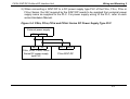
2) When connecting a 32NT-DP to a DC power supply type PLC of the FX0N, FX1N, FX2N or
FX2NC Series, the 24V required by the 32NT-DP needs to be supplied from external power
supply same as supplied to the PLC. For power supply wiring of the PLC, refer to each
series Hardware Manual.
Figure 2.4: FX0N, FX1N, FX2N and FX2NC Series DC Power Supply Type PLC
External power supply
24V
0V
24V
0V
FX0N, FX1N, FX2N, FX2NC
Series DC power supply
type PLC
24V+ 24VG
FX0N-32NT-DP
2-6
FX0N-32NT-DP Profibus-DP Interface Unit
2.2.3
Wiring and Mounting 2
Profibus-DP Wiring
To connect the 32NT-DP to a Profibus-DP network use only the Profibus connectors and
shielded twisted-pair cable complying with EN50170. For Profibus connectors see the Profibus
connector manual.
Figure 2.5: Wiring
For Profibus connector,
refer to Figure 2.6.
Shielded twisted-pair
cable complying with
EN50170 to Profibus-DP
network
DC power supply type PLC: Supply from the external power supply.
AC power supply type PLC: Supply from the service power supply of PLC.
Further information, refer to subsection 2.2.2.
FG
24+
24G
FX0N-32NT-DP
Profibus-DP Interface Unit
Grounding plate
Grounding
resistance of
100 Ω or less
(Class D)
For noise prevention please attach at least 50mm
(1.97") of the twisted-pair cable along the
grounding plate to which the ground terminal is
connected.
2-7
FX0N-32NT-DP Profibus-DP Interface Unit
Wiring and Mounting 2
Figure 2.6: Profibus Connector
Shielded twisted-pair cable to
Profibus-DP network
FX0N-32NT-DP Profibus-DP
Interface Unit
2.2.4
Terminating Resistor
The units at each end of the Profibus-DP network must have a terminating resistor. This will
either be in the master or slave unit or in the Profibus connector.
However, the 32NT-DP does not have a terminating resistance built-in.
2-8
FX0N-32NT-DP Profibus-DP Interface Unit
3.
Specifications
3.1
General Specifications
Specifications 3
Table 3.1: General Specifications
Item
Specifications
General specifications
Same as those for connecting PLC
(excluding withstand voltage)
Withstand voltage
3.2
500V AC for 1 minute (between terminals and earth)
Power Supply Specifications
Table 3.2: Power Supply Specifications
Item
Specifications
Power supply
24V DC +/- 10%, 20mA (when using a twisted-pair cable) / 60mA (when
using a optical glassfiber cable)
Interface power supply
5V DC, 170mA (internal power supply from PLC)
3-1
FX0N-32NT-DP Profibus-DP Interface Unit
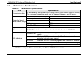
3.3
Specifications 3
Performance Specifications
Table 3.3: Performance Specifications
Item
Transmission data
Specifications
20 words can be sent and received during one bus cycle (default value 16 words).
The number of transmitted words can be changed between 4 and 20 words.
9.6k, 19.2k, 45.45k, 93.75kbps
1,200m
187.5kbps
1,000m
Supported baud
500kpbs
rates and bus length
1.5Mbps
400m
200m
3M, 6M, 12Mbps
Applicable PLC
100m
FX0N, FX1N, FX2N, FX2NC*1 Series PLC
PLC communication FROM/TO instruction is used to read and write data from/to the 32NT-DP
LED indicators
POWER LED
ON when 5V DC power is supplied from the PLC (internal power
supply).
DC LED
ON when 24V DC power is supplied from the power supply
terminals (external power supply).
RUN LED
ON when 32NT-DP is exchanging data with Profibus-DP network.
BF LED
ON when a communication error is detected. (No data exchange)
DIA LED
ON when notice of diagnostic data is detected.
*1 When using an FX2NC series PLC, an FX2NC-CNV-IF is required.
3-2
FX0N-32NT-DP Profibus-DP Interface Unit
4.
Buffer Memories (BFMs) Allocation 4
Buffer Memories (BFMs) Allocation
Caution:
1) Do not access the buffer memory defined as “Not used” (BFM #31) by FROM/TO
instruction. There is a possibility to cause abnormal operation of the 32NT-DP if
accessing these buffer memories.
2) Do not write to (access by TO instruction) the buffer memory defined as “Read only”
(BFM #20, #22 ~ #26, #29, #30) by the programmable controller. It is not possible to
operate the 32NT-DP by writing to (accessing by TO instruction) these buffer memories.
Note:
The sending data and receiving data buffers share the same buffer memory addresses
(BFM #0 ~ #19) for use with FROM and TO instructions. This means it is not possible to
check the buffer memory data using a FROM instruction because this instruction only reads
the receive buffer data.
4-1
FX0N-32NT-DP Profibus-DP Interface Unit
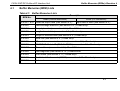
4.1
Buffer Memories (BFMs) Allocation 4
Buffer Memories (BFM) Lists
Table 4.1: Buffer Memories Lists
BFM No.
Description
Read (FROM instruction)
BFM #0 ~ #19 Received output data (see section 4.2.)
Write (TO instruction)
Input data to send (see section 4.2.)
BFM #20
Data exchange status bit (see section 4.3.) <Read only>
BFM #21
Swap byte order (see section 4.4.) <Read/Write>
BFM #22
Length of sent data (see section 4.5.) <Read only>
BFM #23
Length of received data (see section 4.5.) <Read only>
BFM #24
Baud rate (see section 4.6.) <Read only>
BFM #25
DP module communication status (see section 4.7.) <Read only>
BFM #26
PROFIBUS Module ID (PNO-Nr.F032H) see section 4.8. <Read only>
BFM #27
Slave address (see section 4.9.) <Read/Write>
BFM #28
User diagnosis (see section 4.10.) <Read/Write>
BFM #29
Error status (see section 4.11.) <Read only>
BFM #30
Model identification code (K7020) see section 4.12. <Read only>
BFM #31
Not used
4-2
FX0N-32NT-DP Profibus-DP Interface Unit
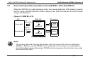
4.2
Buffer Memories (BFMs) Allocation 4
Received Output Data, Input Data to Send (BFM #0 ~ #19) <Read/Write>
When the 32NT-DP is in data exchange mode, the received data from a DP-master is read by
the PLC using a FROM instruction. Data is written to the 32NT-DP and sent to the DP-master
using a TO instruction.
Figure 4.1: BFM #0 ~ #19
PLC
TO
instruction
32NT-DP
BFM #0
Send data
FROM
instruction
DP network
Send
buffer
BFM #19
BFM #0
Receive data
Receive
buffer
BFM #19
Same BFM addresses
Note:
The sending data and receiving data buffers share the same buffer memory addresses
(BFM #0 ~ #19) for use with FROM and TO instructions. This means it is not possible to
check the buffer memory data using a FROM instruction because this instruction only reads
the receive buffer data.
4-3
FX0N-32NT-DP Profibus-DP Interface Unit
4.3
Buffer Memories (BFMs) Allocation 4
Data Exchange Status Bit (BFM #20) <Read Only>
BFM #20 contains a status bit for data exchange. If this value is “1", the module is in data
exchange mode and the received data is valid. If this value is “0", the module is not in data
exchange mode.
4.4
Swap Byte Order (BFM #21) <Read/Write>
Some DP-masters handle lower bytes and higher bytes of a word in reverse order compared to
the 32NT-DP module. To enable the module to communicate with these masters, bit 0 of BFM
#21 can be set. If bit 0 is “1”, the low order byte and the high order byte of each user data word
and of the user specific diagnosis will be swapped. Bit 0 of BFM #21 can also be set or reset
by the second user defined parameter byte received from a master. The default value after
power up is “0”.
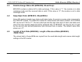
4.5
Length of Sent Data (BFM #22), Length of Received Data (BFM #23)
<Read Only>
The values held in these BFMs are copied from the send data length and receive data length
settings in the DP-master.
4-4
FX0N-32NT-DP Profibus-DP Interface Unit
4.6
Buffer Memories (BFMs) Allocation 4
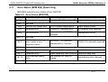
Baud Rate (BFM #24) <Read Only>
BFM #24 shows the current baud rate of the DP network. The baud rate depends on the
DP-master settings. The following table shows the supported baud rates and the value of BFM
#24. If the 32NT-DP is in baud search mode, this value frequently changes until the 32NT-DP
has found a supported baud rate.
Table 4.2: Baud Rate (BFM #24)
Baud Rate (bps)
BFM #24 Value
Baud Rate (bps)
BFM #24 Value
9.6k
96E2H
500k
05E5H
19.2k
19E3H
1.5M
15E5H
45.45k
45E3H
3M
03E6H
93.75k
93E3H
6M
06E6H
187.5k
18E4H
12M
12E6H
Note:
96E2 = 96 × 102 = 9,600 = 9.6k baud rate
4-5
FX0N-32NT-DP Profibus-DP Interface Unit
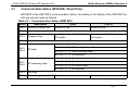
4.7
Buffer Memories (BFMs) Allocation 4
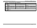
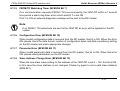
Communication Status (BFM #25) <Read Only>
BFM #25 is the 32NT-DP’s communication status. According to the status of the 32NT-DP the
bits are set and reset as follows.
Table 4.3: Communication Status (BFM #25)
Bit No.
Description
Bit 0
Module on-line/off-line
Bit 1
Not used
Bit 2
Diagnosis flag
Bit 3
Not used
1 (ON)
0 (OFF)
Module on-line
Module off-line
New diagnosis not yet fetched by
DP-master
New diagnosis fetched by
DP-master
(b5, b4) = (0, 0): Wait parameter state
Bit 5,
Bit 4
DP-state
(b5, b4) = (0, 1): Wait configuration state
(b5, b4) = (1, 0): Data exchange state
(b5, b4) = (1, 1): Not possible
(b7, b6) = (0, 0): Baud search state
Bit 7,
Bit 6
DP-watchdog state
(b7, b6) = (0, 1): Baud control state
(b7, b6) = (1, 0): DP control state
(b7, b6) = (1, 1): Not possible
Bit 8
Not used
Bit 9
Clear data global control Clear data command received
No clear data command received
4-6
FX0N-32NT-DP Profibus-DP Interface Unit
Buffer Memories (BFMs) Allocation 4
Table 4.3: Communication Status (BFM #25)
Bit No.
Description
1 (ON)
0 (OFF)
Bit 10
UNFREEZE global
control
UNFREEZE command received
No UNFREEZE command
received
Bit 11
FREEZE global control
FREEZE command received
No FREEZE command received
Bit 12
UNSYNC global control
UNSYNC command received
No UNSYNC command received
Bit 13
SYNC global control
SYNC command received
No SYNC command received
Bit 14,
Not used
Bit 15
4-7
FX0N-32NT-DP Profibus-DP Interface Unit
4.7.1
Buffer Memories (BFMs) Allocation 4
Global Control Command
The global control commands are processed by the 32NT-DP itself and require no specific
measures from the programmable controller user program.
1) Clear data global control
When this command is received, the 32NT-DP clears the output data.
2) UNFREEZE global control
The UNFREEZE command stops freeze control mode. Data written with a TO instruction is
immediately sent to the DP-master.
3) FREEZE global control
The DP-master sends a FREEZE control command to a group of DP-slaves to freeze their
current input states. Data written with a TO instruction is withheld until the next FREEZE/
UNFREEZE command is received.
4) UNSYNC global control
The UNSYNC command stops SYNC control mode. Data sent from the DP-master is
immediately transmitted to the BFM to be read using a FROM instruction.
5) SYNC global control
The DP-master sends a SYNC control command to a group of
DP-slaves to synchronize their current output states. Data read with a FROM instruction
remains constant until the next SYNC/UNSYNC command is received.
4-8
FX0N-32NT-DP Profibus-DP Interface Unit
4.8
Buffer Memories (BFMs) Allocation 4
PROFIBUS Module ID (BFM #26) <Read Only>
This buffer memory contains the Profibus module ID number for the 32NT-DP. The ID number
is “F032H”.
4.9
Slave Address (BFM #27) <Read/Write>
The 32NT-DP supports setting of the DP-slave address by a Profibus-DP class 2 master via
the network and by PLC via a TO instruction. The address is stored in BFM #27. When
changing the address using the TO instruction the new address values must be written to BFM
#27. The address value is 0 ~ 126. The default value of BFM #27 is set to “126”.
Users should avoid exchanging data with a slave with address #126. An address change is
necessary.
4-9
FX0N-32NT-DP Profibus-DP Interface Unit
4.10
Buffer Memories (BFMs) Allocation 4
User Diagnostics (BFM #28) <Read/Write>
By writing to BFM #28 the user can transmit high priority diagnostic data to the DP-master.
Data from BFM #28 is transmitted as external diagnostic data to the DP-master where it can
be used in the master application. If this diagnosis possibility is used, the user must decide the
meaning of the particular bits and the reaction of the master program. This feature could be to
map the error bits. An example for use is shown in the following table.
Table 4.4: User Diagnostics (BFM #28)
Bit
Description
Bit 0
User sets for error-1
Bit 1
User sets for error-2
Bit 2
User sets for error-3
:
:
Bit 15
:
:
User set for error-16
4-10
FX0N-32NT-DP Profibus-DP Interface Unit
4.11
Buffer Memories (BFMs) Allocation 4
Error Status (BFM #29) (Read Only)
BFM #29 indicates error status of the 32NT-DP.
Table 4.5: Error Status (BFM #29)
Bit No.
Description
1 (ON)
0 (OFF)
Bit 0
General error
Bit 1
Not used
Bit 2
External 24V power error
24V DC power supply failure
Power supply normal
Bit 3
Hardware error
Profibus-DP hardware error
No hardware error detected
Bit 4
EEPROM error
Address data in EEPROM are
corrupted
Address data normal
No FROM / TO instruction
received with in 1 second
FROM / TO instruction received
Config data valid
Bit 5, 6
Bit 7
This bit is ON if b2 ~ b4 are ON No general error
Not used
FROM / TO watchdog
timer (visible only in
diagnosis frame)
Bit 8, 9
Not used
Bit 10
Configuration error
Invalid config data received
Bit 11
Parameter error
Invalid parameter data received Parameter data valid
Bit 12
Slave address change
error
New address not valid, no
change
New address valid, changed
Bit 13 ~ 15 not used
4-11
FX0N-32NT-DP Profibus-DP Interface Unit
4.11.1
Buffer Memories (BFMs) Allocation 4
General Error (BFM #29 Bit 0)
When a general error occurs (bit 0 = ON) the 32NT-DP tries to send the data of BFM #28 and
#29 as a static diagnosis message to the DP-master. In this case data can not be exchanged
with the DP-master. After bit 0 returns to OFF, the static diagnosis message is also reset.
4.11.2
External 24V Power Error (BFM #29 Bit 2)
If a 24V DC power supply failure occurs, this bit is ON. If this error occurs, check 24V DC
power supply of the 32NT-DP.
4.11.3
Hardware Error (BFM #29 Bit 3)
If a hardware error of the 32NT-DP occurs, this bit is ON. If this error occurs, please contact a
service representative.
4.11.4
EEPROM Error (BFM #29 Bit 4)
When address data in EEPROM is corrupted, this bit is ON. If this error occurs, try to set the
slave address (BFM #27).
4-12
FX0N-32NT-DP Profibus-DP Interface Unit
4.11.5
Buffer Memories (BFMs) Allocation 4
FROM/TO Watchdog Timer (BFM #29 Bit 7)
If no communication requests (FROM / TO) are received by the 32NT-DP within a 1 second
time period a watch dog timer error occurs and bit 7 is set ON.
If bit 7 is ON, an external diagnosis message will be sent to the DP-master.
Note:
If no FROM / TO instructions are sent to the 32NT-DP an error will be signaled in the DPmaster.
4.11.6
Configuration Error (BFM #29 Bit 10)
When invalid configuration data is received from the DP-master, this bit is ON. When this bit is
ON, please check the data format, number of configuration bytes and data consistency setting
on the DP-master and make appropriate changes.
4.11.7
Parameter Error (BFM #29 Bit 11)
When invalid parameter data is received from the DP-master, this bit is ON. When this bit is
ON, please check parameters on the DP-master.
4.11.8
Slave Address Change Error (BFM #29 Bit 12)
When the new slave value setting for the address of the 32NT-DP is not 0 ~ 126, this bit is ON.
In this case the slave address is not changed. Please try again to set a valid slave address
(BFM #27).
4-13
FX0N-32NT-DP Profibus-DP Interface Unit
4.12
Buffer Memories (BFMs) Allocation 4
Model identification code (BFM #30) <read only>
The identification number for a 32NT-DP is read by using the FROM instruction. The
identification number for the 32NT-DP is K7020. By reading this identification number, the user
may create built-in checking routines to check whether the physical position of the 32NT-DP
matches to that of the software.
4-14
FX0N-32NT-DP Profibus-DP Interface Unit
5.
Setting Operation 5
Setting Operation
For details how to set-up a DP-master please refer to the appropriate DP-master manuals.
5.1
Installing 32NT-DP Parameters in the DP-master
To be able to exchange data with a DP-master the 32NT-DP must receive a valid parameter
and configuration data message from the DP-master.
The 32NT-DP parameters are stored in the GSD File*1 (General Station Description File).
This file must be read by the configuration software of the DP-master. Then it is the task of the
user to set the DP-slave address and the number and format of the input and output words to
the configuration data. After which the configuration can be downloaded to the DP-master.
*1 Please ask your vendor for the GSD files.
5.1.1
DP-slave Address Setting in the DP-master
A DP-master of class 2 or more can set a DP-slave address from the DP-master. For details of
how to set-up a DP-master please refer to the appropriate DP-master manuals.
5-1
FX0N-32NT-DP Profibus-DP Interface Unit
5.1.2
Setting Operation 5
Setting the Number and Format of Input and Output Words in the DP-master
The 32NT-DP supports only word data format and word consistency. Combinations of 2
modules and 4 modules can be configured.
The configurations shown in the following table are possible.
Table 5.1: Setting the Number and Format of Input and Output Words
Module
1st
2nd
Configuration
1
2
3
4
5
16 words input
16 words input
4 words input
16 words input
4 words input
4 words output
4 words output
16 words output
16 words output 16 words output
3rd
4 words input
-
-
-
-
4th
4 words output
-
-
-
-
5-2
FX0N-32NT-DP Profibus-DP Interface Unit
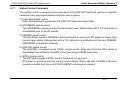
5.2
Setting Operation 5
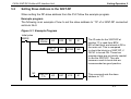
Setting Slave Address in the 32NT-DP
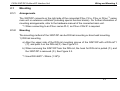
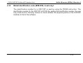
When setting the DP-slave address from the PLC follow the example program.
Example program
The following is an example of how to set the slave address to “10” of a 32NT-DP connected
as block No.0.
Figure 5.1: Example Program
Initial pulse
M8002
FNC 78
FROM
K0
FNC 10
CMP
M1
FNC 79
TO
K0
K30
D0
K1
D0
K7020
M0
K27
K10
K1
The ID code for the 32NT-DP at
position “0” is read from BFM
#30 of that block and stored at D0 in
the main unit. This is compared
to check the block is a 32NT-DP, if
OK M1 is turned ON. These two
program steps are not strictly needed
to use the 32NT-DP. They are
however a useful check and are
recommended as good practice.
This command sets the slave
address to “10”.
5-3
FX0N-32NT-DP Profibus-DP Interface Unit
Setting Operation 5
MEMO
5-4
FX0N-32NT-DP Profibus-DP Interface Unit
6.
Example Program 6
Example Program
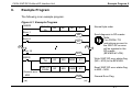
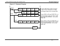
The following is an example program.
Figure 6.1: Example Program
M8002
FNC 79
TO
K0
K21
K0
Error-1
Note:
(a)
If no FROM / TO
instructions are sent to
the 32NT-DP an error
will be signaled in the
DP-master
(BFM #29 b7=ON).
M1
Error-16
General error
M20
Send diagnosis to DP-master
M0
Error-2
M8000
Normal byte order
K1
M15
FNC 79
TO
K0
K28
K4M0
K1
Write 32NT-DP error status flag
(M0 ~ M15) to the BFM #28.
FNC 78
FROM
K0
K29
K4M20
K1
Read 32NT-DP error status flag
to M20 ~ M35.
General Error Flag
Y000
(a)
6-1
FX0N-32NT-DP Profibus-DP Interface Unit
Example Program 6
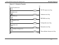
Figure 6.1: Example Program
(a)
24V DC power error
M22
(a)
Y001
24V DC power error flag
Y002
Hardware error flag
Y003
EEPROM error flag
Y004
Configuration error flag
Y005
Parameter error flag
Y006
Slave address change error flag
Hardware error
M23
EEPROM error
M24
Configuration error
M30
Parameter error
M31
Slave address change error
M32
(b)
(b)
6-2
FX0N-32NT-DP Profibus-DP Interface Unit
Example Program 6
Figure 6.1: Example Program
(b)
(b)
M8000
FNC 78
FROM
K0
FNC 10
CMP
M41
X000
X001
K20
D0
K1
D0
K1
M40
FNC 78
FROM
K0
K0
D30
K20
FNC 79
TO
K0
K0
D10
K20
Check 32NT-DP in data exchange
mode. When 32NT-DP is in data
exchange mode, M41 is turned ON.
When X000 is ON and 32NT-DP is in
data exchange mode, the PLC reads
input data from BFM #0 ~ #19 in the
32NT-DP.
When X001 is ON and 32NT-DP is in
data exchange mode, the PLC writes
output data to BFM #0 ~ #19 in the
32NT-DP.
END
6-3
FX0N-32NT-DP Profibus-DP Interface Unit
Example Program 6
MEMO
6-4
FX0N-32NT-DP Profibus-DP Interface Unit
7.
Diagnostics
7.1
Preliminary Checks
Diagnostics 7
1) Check POWER and DC LED. If this is OFF, please see section 7.2.
2) Check that the slave address is the same at the 32NT-DP (BFM #27) and the setting value
of the Profibus-DP master configuration tool. If the slave address is not the same, change
this address to match at both sides.
3) Check that the parameters of 32NT-DP are set in the DP-master.
4) Check whether the network wiring and /or extension cables are properly connected on the
32NT-DP.
5) Check that the system configuration rules have not been exceeded (i.e. the number of
blocks does not exceed 8 and the total system I/O is equal or less than 128*1 I/O).
*1 FX0N, FX1N Series PLC is 128 I/O points.
FX2N, FX2NC Series PLC is 256 I/O points.
6) Put the PLC into RUN.
7-1
FX0N-32NT-DP Profibus-DP Interface Unit
7.2
Diagnostics 7
LED Check
Check the status of the LED’s for the 32NT-DP as follows.
1) DC LED check
Table 7.1: DC LED Check
Status
Description
Lit
32NT-DP is OK, 24V DC power source is OK.
Otherwise
Possible 24V DC power failure, if OK then possible 32NT-DP failure.
2) POWER LED check
Table 7.2: POWER LED Check
Status
Description
Lit
The extension cable is properly connected.
Otherwise
Check the connection of the 32NT-DP extension cable to the PLC.
7-2
FX0N-32NT-DP Profibus-DP Interface Unit
Diagnostics 7
3) RUN, BF and DIA LED check
z:
ON
{: OFF
Table 7.3: RUN, BF and DIA LED Check
RUN LED
BF LED
DIA LED
Status
Action
z
{
{
Normal operation
{
z
{
No communication/baud search mode
Point a)
z
{
z
External diagnostic error
Point b)
{
z
z
Static diagnostic error
Point c)
a) Check BFM #24. If BFM #24 does not show a stable baud rate (i.e. always changing)
then check DP-network cables. Check BFM #29. If BFM #29 is not “0” refer to section
4.11 for details.
b) Check BFM #28. (User error flags)
c) Check b0 ~ b7 of #29. If b0 ~ b7 of BFM #29 is not “0”, refer to section 4.11 for details.
7.3
Check BFM #29 error status of the 32NT-DP
If BFM #29 is not “0”, refer to section 4.11 for details.
7-3
FX0N-32NT-DP Profibus-DP Interface Unit
Diagnostics 7
MEMO
7-4
FX0N-32NT-DP Profibus-DP Interface Unit
Appendix A
Appendix A:
Further Information Manual List
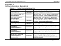
Table A-1:
Further Information Manual List
Manual name
Manual No.
Description
FX2N Series PLC
Hardware Manual
JY992D66301
Describes FX2N Series PLC specification details for
I/O, wiring, installation and maintenance.
FX2NC (DSS/DS) Series PLC
Hardware Manual
JY992D76401
Describes FX2NC (DSS/DS) Series PLC specification
details for I/O, wiring, installation and maintenance.
FX2NC (D/UL) Series PLC
Hardware Manual
JY992D87201
Describes FX2NC (D/UL) Series PLC specification
details for I/O, wiring, installation and maintenance.
FX1N Series PLC
Hardware Manual
JY992D89301
Describes FX1N Series PLC specification details for
I/O, wiring, installation and maintenance.
FX0/FX0N Series PLC
Hardware Manual
JY992D47501
Describes FX0 and FX0N Series PLC specification
details for I/O, wiring, installation and maintenance.
FX Series PLC
Programming Manual ΙΙ
Describes FX1S, FX1N, FX2N and FX2NC Series PLC
JY992D88101 programming for basic/ applied instructions and
devices.
FX Series PLC
Programming Manual
Describes FX0, FX0S, FX0N, FX and FX2C Series PLC
JY992D48301 programming for basic/ applied instructions and
devices.
MELSEC-Q/L/F Structured
Programming Manual
(Fundamentals)
SH-080782
This manual contains explanations for the
programming method, types of programming
languages and other information required to create
structured programs.
A-1
FX0N-32NT-DP Profibus-DP Interface Unit
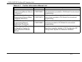
Table A-1:
Further Information Manual List
Manual name
Manual No.
Description
FX CPU Structured
Programming Manual (Device
& Common)
This manual contains explanations for the devices
JY997D26001 and parameters provided in GX Works2 for structured
programming.
FX CPU Structured
Programming Manual (Basic
& Applied Instruction)
This manual contains explanations for the sequence
JY997D34701 instructions provided in GX Works2 for structured
programming.
FX CPU Structured
Programming Manual
(Application Functions)
This manual contains explanations for the application
JY997D34801 functions provided in GX Works2 for structured
programming.
GX Configurator-DP
Configuration System for
Open Networks Software
Manual
-
Describes operation details of GX Configurator-DP
Configuration System for Networks Software.
A-2
USER’S MANUAL
FX0N-32NT-DP Profibus-DP Interface Unit
HEAD OFFICE:
JY992D61401H
(MEE)
TOKYO BUILDING, 2-7-3 MARUNOUCHI, CHIYODA-KU, TOKYO 100-8310, JAPAN
Effective April 2015
Specification are subject to change without notice.