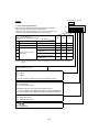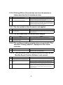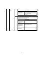
1
FILE NO. A10-026
SERVICE MANUAL
SMART MANAGER
Model name:
BMS-SM1280HTLE
PRINTED IN JAPAN, Mar, 2011
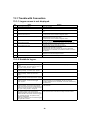
Contents
SAFETY PRECAUTIONS . . . . . . . . . . . . . . . . . . . . . . . . . . . . . . . . . . . . . . . . . . . . . . . . . . 3
1 PRODUCT OVERVIEW. . . . . . . . . . . . . . . . . . . . . . . . . . . . . . . . . . . . . . . . . . . . . . . . . . 5
2 SYSTEM CONFIGURATION. . . . . . . . . . . . . . . . . . . . . . . . . . . . . . . . . . . . . . . . . . . . . . 6
3 LIST OF FUNCTIONS . . . . . . . . . . . . . . . . . . . . . . . . . . . . . . . . . . . . . . . . . . . . . . . . . . . 8
4 PRODUCT SPECIFICATION . . . . . . . . . . . . . . . . . . . . . . . . . . . . . . . . . . . . . . . . . . . . 10
5 INSTALLATION OF THE SMART MANAGER. . . . . . . . . . . . . . . . . . . . . . . . . . . . . . . 12
6 CONNECTION OF POWER CABLES / EARTH WIRES / COMMUNICATION CABLES . . . 15
7 PRODUCT CONNECTION DIAGRAM . . . . . . . . . . . . . . . . . . . . . . . . . . . . . . . . . . . . . 18
8 SWITCHES FOR SETTING (Smart Manager) . . . . . . . . . . . . . . . . . . . . . . . . . . . . . . . 20
9 MODE SETTING FOR SMART MANAGER . . . . . . . . . . . . . . . . . . . . . . . . . . . . . . . . . 26
10 ZONE SETTING . . . . . . . . . . . . . . . . . . . . . . . . . . . . . . . . . . . . . . . . . . . . . . . . . . . . . . 27
11 CHANGING RETURN-BACK TIME / TEMPERATURE SETTINGS. . . . . . . . . . . . . . . 28
12 TEST RUN. . . . . . . . . . . . . . . . . . . . . . . . . . . . . . . . . . . . . . . . . . . . . . . . . . . . . . . . . . . 29
13 TROUBLESHOOTING . . . . . . . . . . . . . . . . . . . . . . . . . . . . . . . . . . . . . . . . . . . . . . . . . 31
14 TEST RUN CHECK . . . . . . . . . . . . . . . . . . . . . . . . . . . . . . . . . . . . . . . . . . . . . . . . . . . . 42
15 CHECK POINTS . . . . . . . . . . . . . . . . . . . . . . . . . . . . . . . . . . . . . . . . . . . . . . . . . . . . . . 48
16 EXPLODED VIEWS AND PARTS LIST . . . . . . . . . . . . . . . . . . . . . . . . . . . . . . . . . . . . 52
2
SAFETY PRECAUTIONS
Important safety-related information is described on the product and in this Service Guide.
Read the following description on labels and symbols carefully and follow their directions.
[Explanation of labels]
Label
Explanation
DANGER
Indicates that the repair engineer and other third-party individuals in the vicinity may be
exposed to immediate risk of death or serious injury if operation is not performed correctly.
WARNING
Indicates that the repair engineer and other third-party individuals in the vicinity may be
exposed to a risk of death or serious injury if operation is not performed correctly.
CAUTION
Indicates that the repair engineer and other third-party individuals in the vicinity may be
exposed to a risk of injury or that property damage (*) may result if operation is not performed
correctly or from failure of product after operation.
(*): Property damage means expanded damages to assets, furniture, livestock and / or pets.
[Explanation of symbols]
Symbol
Explanation
Indicates prohibited activity
Specific prohibited actions are described in statements near the symbol.
Indicates enforced action
Specific enforced actions are described in statements near the symbol.
Indicates caution (includes danger alert and warning)
Specific content of caution is indicated in a picture or statement near the symbol.
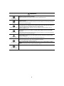
DANGER
Turn off breaker before performing work.
Otherwise, one may receive electric shock from the high-voltage electricity, resulting in death or
injury.
Turn off breaker
Do not turn on the breaker when the cover of the unit is removed.
Otherwise, one may receive electric shock from the high-voltage electricity, resulting in death or
injury.
Prohibition
WARNING
Before fault diagnosis or beginning repair work, make sure that the ground wire is
connected to the ground terminal of the unit.
If not, ground leakage may result in electric shock hazard.
Check for ground wire
Do not alter the product.
Components of the unit should also not be taken apart or altered.
Otherwise, it may result in fire, electric shock or injury.
No alteration
Use designated parts for replacement.
Using parts other than those designated may cause fire or electric shock.
Use designated parts
3
WARNING
Do not allow unauthorized personnel other than repair engineers to enter areas where fault
diagnosis and repair work is conducted.
Unauthorized persons may suffer injury from tools and disassembled parts.
Restricted area
Insulation
Assembly wiring caution
Insulation check
Electric shock caution
Connect lead wires with crimping terminals and turn the closed end upwards to avoid
exposure to water.
Failure to perform this post-connection treatment may cause disasters, such as electricity leakage
and fire, on the client’s premises.
After repair, ensure that the assembly of disassembled parts and the connection and wiring
of removed wires are completed so as to restore them to their former state. Be careful not
to have the internal wires caught in the cover or other closures.
A defect in assembly or wire connection may cause disasters in the client premise, such as
electricity leakage and fire.
After repair, check for insulation between the charged part and non-charged metal part
(ground terminal) using an insulation resistance tester (500V) and ensure at least 2MΩ
resistance.
If the insulation resistance value is low, it indicates the risk of disasters, such as electricity leakage
and electric shock, on the client’s premises.
In case of performing circuit inspection while the circuit is connected to a power source (if
such condition is necessary), use rubber gloves and other measures to prevent contact
with the charged part.
Otherwise, one will risk electric shock from contacting the charged part.
Upon completion of repair, ensure that there are no abnormalities.
Risks of fire, electric shock or injury may be prevented by inspection.
Turn off the breaker before performing inspection.
Check after repair
Test run the system after repair and make sure that there are no abnormalities including
smoke.
Risks of fire and electric shock may be prevented by inspection.
Repair and reinstallation must be performed by qualified professional.
Repair and Reinstall
4
1
PRODUCT OVERVIEW
This product is an air-conditioning control system to control and monitor the operation state of air conditioners in a
building by using a computer with the mouse at a customer site. The system enables intensive management,
operation control, and energy-saving operation for the air conditioners of up to 128 groups. The display and
operation are available on a Web browser. This does not require dedicated software to be installed in a PC, and
enables up to 4 units of PC to access simultaneously the system.
1-1. Main Functions
Monitoring / Controlling Air Conditioners
Enables users to monitor the operating status, setup status, and error status of all their air conditioners, to start and
stop all theirs air conditioners, and change the setup details of all their air conditioners.
The air conditioners are named and categorized in a hierarchy by each floor, tenant, area, and air conditioning
system. When controlling the air conditioners, they can be set in batch by each floor, tenant, or area, or they can
be set individually for each air conditioning system.
The air conditioners can be controlled by linking to the locking signals and the fire alarm signals.
Scheduled Operation for Air Conditioners
Operation of all air conditioners can be scheduled. Up to 10 setups can be programmed for each day, and it is
possible to prevent users from forgetting to switch off by setting a stop schedule. During scheduled operation, users
can set the Power status (On / Off), Operation mode, Temperature setup, Remote control operation restricted /
allowed, and Return back.
In the master schedule, users can set weekly schedules and five types of special day schedules, as well as monthly
schedules for up to 12 months.
Distributing Power used by Air Conditioners
It is possible to distribute the power to be used for each air conditioner. In the billing schedule setup, it is possible
to monitor the operation time period and power distribution during both working hours and non-working hours
separately.
Note that power distribution requires the Energy Monitoring Relay Interface (sold separately).
Warning List
Displays all current warnings in a list. Warning history is also displayed in a list.
5
2
SYSTEM CONFIGURATION
Alarm output
TCC-LINK
Operation output
Schedule Timer
Outdoor unit
All operation
Fire alarm input
All Stop
Indoor unit
TCC-LINK
Central Controller
HUB
RS-485
Ethernet
PC
Energy Monitoring
Relay I/F
Electric energy meter
Electric energy meter
Electric energy meter
Digital I/O
Relay I/F
Fire alarm input
Lock input
Alarm output
6
System Devices Configuration
EXTENDED SYSTEM
Device Name
Number of Units
Connected
Model
Indoor Unit
(TCC-LINK based model)
Energy Monitoring Relay Interface
BMS-IFWH5E
Max 128
Up to 64 units per line
Up to 128 units in total for 2 lines
Max 4
Up to 8 electric energy meters per
BMS-IFWH5E
Max 4
Up to 8 lock inputs or fire alarm
inputs per BMS-IFDD03E
Digital Input / Output Relay Interface BMS-IFDD03E
Central Remote Controller
TCB-SC642TLE
BMS-CM1280TLE
Client PC
(Windows based model)
Max10
—
Up to 4 units for simultaneous
access
—
OS
Client PC spec
Remarks
Windows XP, Vista, 7
Browser
Internet Explorer 6.0 / 7.0 / 8.0 or Firefox 2.0 / 3.0 / 3.5 / 3.6
Display
1,024 X 768 more
2-1. Communication Specification
TCC-LINK
RS-485
Ethernet
Topology
Bus
Signal wire type
2-core shield wire
Wire size, length
For 1.25mm2 (AWG16), up to 1,000 m (Total length)
For 2.00mm2 (AWG14), up to 2,000 m
Number of nodes
Up to 100
(Total of Indoor unit, Outdoor unit, Central Remote Controllers and Interfaces)
Transmission rate
9.6kbps
Polarity
Not exist
Topology
Bus
Signal wire type
2-core shield wire
Transmission distance
Up to 500 m (Total length)
Number of nodes
Up to 32
Transmission rate
115.2kbps
Polarity
Exist
Network interface
10BASE-T / 100BASE-TX (Auto sensing)
Transmission rate
10 M bps (10BASE-T)
100 M bps (10BASE-TX)
Transmission media
For 10BASE-T: Category 3 or Category 5
For 100BASE-TX: Category 5 (*)
Straight / Crossover
Use a straight or crossover cable depending on use.
Length
Maximum segment length: 100 m
Connection
RJ-45 connector
(*) LAN cable: Unshielded twisted pair (UTP)
7
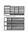
3
LIST OF FUNCTIONS
Function
User account
Air conditioner category
Details
Number of user registrations
32
Type of user account
Administrator
Power user
Guest
Category structure
3 levels
9
Monitoring air conditioner status Start / Stop
Controlling air conditioner
Operation schedule
Master schedule
Operation mode
9
Set temperature
9
Fan speed
9
Louver
9
Remote control prohibition /
permission
9
Warning
9
Filter sign
9
Room temperature
9
Return back
9
Vetilation mode
9
Start / Stop
9
Operation mode
9
Set temperature
9
Fan speed
9
Louver
9 SWING / NO SWING
Remote control prohibition /
permission
9
Filter sign reset
9
Return back
9
Vetilation mode
9
Number of registrations
Equivalent to the number of indoor units
Settable period
7 days, Up to 1 week later including current date
Number of set points per day
10 settings
Interval of set point
1 minute
Settable parameters
Start / Stop
Operation mode
Set temperature
Remote control prohibition / permission
Return back
Vetilation mode
Number of registrations
32
Settable period
Up to 12 months later including current month
Number of set points per day
10 settings
Interval of set point
1 minute
Settable parameters
Start / Stop
Operation mode
Set temperature
Remote control prohibition
Return back
Vetilation mode
Weekly schedule pattern
By day schedule: 7 patterns, Monday through Sunday
Special day schedule pattern
By special day schedule: 5 patterns
Schedule assigning unit
By indoor unit
8
Function
Billing schedule
Warning display
Warning history display
Details
Number of registrations
32
Singularity settable period
Up to 12 months later including current month
Number of set points per day
10 settings
Interval of set point
1 minute
Number of days assigned
special day schedule
45 days per a special day schedule
Settable parameters
Working hours / Non-working hours
Number of schedule patterns
By day schedule: 7 patterns, Monday through Sunday
By singularity schedule: 5 patterns
Date / Time of warning
9
Warning code
9
Warning details
9
Number of cases
1024
Date / Time of warning
9
Warning code
9
9
Warning details
9
Power distribution
Data keeping period
Daily report file: Stored for 45 days
Monthly report file: Stored for 3 months
Files that exceeded their keeping period are automatically
deleted.
Automatic meter reading
9
Manual meter reading
9
Centigrade / Fahrenheit Temperature display switching
9
Set temperature Unit of 1°C or 0.5°C switching
9
Return back
9 (Only settable on scheduler)
Control by linking to locking signal
9
Control by linking to fire alarm signal
9
Operation mode restriction
9
Time setting
9
9
4
PRODUCT SPECIFICATION
BMS-SM1280HTLE (Smart Manager)
Central Controller
140
Power supply
Use the supplied power unit.
Power consumption
Operating
0 to 40 °C, 10 to 90% RH
temperature / humidity (no condensation)
19
45
Dimensions
120(H) x 180(W) x 64(D) mm
Mass
0.8 kg
90
120
180
Power Unit
182.7
177
Power supply
220 - 240 VAC, 50 / 60 Hz
Power consumption
7W
Operating
0 to 40 °C, 10 to 90% RH
temperature / humidity (no condensation)
12
102
114
52.4
50
90
12
6-Ø5.5
153
153
12
12
10
Dimensions
114(H) x 177(W) x 50(D) mm
Mass
0.9 kg
BMS-IFWH5E (Energy Monitoring Relay Interface)
246
234
6-Ø5.5
mounting holes
66
63.6
77
220 - 240 V, AC 50 / 60 Hz
Power consumption
4W
Operating temperature /
humidity
0 to 40 °C, 10 to 90% RH
Storage temperature
-20 to +60 °C
Dimensions
66(H) x 193(W) x 246(D) mm
Mass
1.35 kg
Power Power meter input Photo-coupler insulation
meter
Input points
8 points
input
Input resistance
3 k ohm
Input “ON” current 3.6 mA
77
193
193.4
120
193
246
219
Power supply
34
Input pulse condition 50msec or more
BMS-IFDD03E (Digital Input / Output Relay Interface)
246
234
6-Ø5.5
mounting holes
193
193.4
77
77
120
66
63.6
220 - 240 V, AC 50 / 60 Hz
Power consumption
5W
Operating temperature /
humidity
0 to 40 °C, 10 to 90% RH
Storage temperature
-20 to +60 °C
Dimensions
66(H) x 193(W) x 246(D) mm
Mass
1.35 kg
Digital Input type
input
Input points
Photo-coupler insulation
Input resistance
3 k ohm
Open collector
4 points
Output current
Max. 35 mA (per point)
Output voltage
Less than DC 24V
External power supply for
Input / Output
11
8 points
Input “ON” current 3.6 mA
Digital Output type
output
Output points
34
193
246
219
Power supply
DC 12 V, 90 mA
5
INSTALLATION OF THE SMART MANAGER
CAUTION
• Do not twist communication wires (used between indoor unit and outdoor unit and used for central control) and input/
output wires with power wires or bundle them together with power wires in a metal tube. Doing so may cause
malfunction.
• Install the Smart Manager away from a noise source.
• When noise is induced into the power supply of the Smart Manager, take proper measures such as attaching of a
noise filter.
Central Controller box
Insert a flat-blade screwdriver or the like into
the right and left grooves at the bottom of the
panel, and then carefully detach the panel.
Base
Panel
This hole is provided for penetration of the
Central Controller box fixing screw.
Fix the panel by hooking the nails.
155
8.5
5Ø
Dimensions of unit fixing holes in the wall, etc.
142
12.7
108
76
106.6
17.9
8.5
65
172
12
Power Unit Installation Method and Orientation
There are five installation methods for this power unit as shown below: surface mount and wall mounts. Use the
attached screws.
No good
REQUIREMENT
Do not install the unit in any of the following places.
• Humid or wet place
• Dusty place
• Place exposed to direct sunlight
• Place where there is a TV set or radio within one meter
• Place exposed to rain (outdoors, under eaves, etc.)
Installation Space and Maintenance Space
A side space for connecting through cable inlets and an upper space for maintenance
must be reserved before installation.
The other sides can be adjacent to surrounding objects.
100mm
100mm
13
Combining the Central Controller and Power Unit
You can combine the central controller and power unit using the supplied brackets as follows in order to control
them as one unit
Power unit
Bracket
Panel
Combination method
Fix the brackets and the central
controller box together using the
screws on the box.
Fix the power unit to the brackets
using the bracket screws.
14
6
CONNECTION OF POWER CABLES /
EARTH WIRES / COMMUNICATION CABLES
Connect power cables, communication cables, and earth wires to the specified terminals on the terminal block.
REQUIREMENT
Attach a round pressure terminal to the end of each wire except those for digital input and output.
The power terminals on the central
controller have polarity. Make sure
to connect the cables correctly.
Other wise failure will occur.
TCC-LINK U1 and U2
have no polarity.
The RS-485 signal wire has
polarity A and B. Be careful
when connecting the wire.
WT
D O2
C OM
D O1
D I3
4
C OM
3
D I2
2
D I1
Power Supply Unit
1
TCC-LINK1
U1
U2
TCC-LINK2
FG
U1
U2
RS-485
FG
A
B
RS-485
communication
cable
TCC-LINK
communication
cable 1
The TCC-LINK
communication cable
must be earthed on the
air conditioner. Do not
connect the shield wire
to the terminal block. It
should be open and
insulated.
central
controller
power cable
Outdoor
Unit
Indoor Unit
Remote
controller
TCC-LINK communication
cable 2
Connect the shield
wire of the RS-485
communication
cable to the FG
terminal.
Connect to the
Energy Monitoring
relay Interface and
Digital Input / Output
relay Interface
Outdoor
Unit
Indoor
Unit
Remote
controller
Weekly timer
(sold separately)
LAN cable
Client PC
Clamp filter
N
Power supply
220-240V AC
L
4
Power
cable
3
2
1
Fix the cable
securely with the
clamp.
Functional
earth
Connect the earth wire securely to
the earth terminal on the unit.
15
Connect the functional earth terminal
with the earth near the central controller.
Length of stripped power cable
Length of stripped TCC-LINK
communication cable
Length of stripped RS-485
communication cable
35
35
Length of stripped digital Input /
Output communication wire
35
35
6
L
N
55
55
Attach a round pressure terminal to
the end of each wire of the power
cable, communication cable and
power cable for central controller.
Attach the supplied clamp filter to the LAN cable.
* Wind the LAN cable around the clamp filter as shown
below when attaching the filter to the cable. After
attaching the filter, fix it to the LAN cable using a
supplied tie-wrap.
* Attach the clamp filter as near the main unit as possible.
Loosen the screw with the screw
driver, insert the digital input / output
communication wire, then tighten
the screw again to fix the wire firmly.
LAN cable
Round pressure
terminal
REQUIREMENT
• Disconnect the appliance from the main power supply.
This appliance must be connected to the main power supply by a circuit breaker or switch with a contact
separation of at least 3mm.
• Fasten the screws to the terminal with torque of 0.5Nm.
Connections to External Equipment
Example of connection to external equipment which is connected to digital input / output connector.
Designation
Input /
Output
item
Central Controller side
Input / output
conditions
External equipment side
Terminal name
Example of circuit
Input / output
conditions
DO1
DO1
(Alarm output)
DO2
(Run output)
DO-COM
(Output
common)
Status
output
Allowable
terminal voltage
/ current
DC24V / 35mA
DO2
Digital
output
Wiring length:
100 m or less
DO-COM
5V
DI1
(All stop input)
DI2
(All start input)
DI3
(Fire alarm
input)
DI-COM
(Input
common)
Non-voltage A
contacts
Pulse or static
Control
input
* Non voltage
contacts must
be compatible
with minimal
current.
DC5V / 3mA
DI1
Pulse or static
DI2
Pulse or static
DI3
Static
5V
Pulse width:
300 ms or more
5V
DI-COM
16
Wiring length:
100 m or less
<Specifications for Wiring>
Use the following materials to connect signal lines and power lines (locally procured)
No
Line
Type / Wire size / Length
1
For TCC-LINK
2
For RS-485
3
For power
(220 - 240VAC)
H05RN-F or 245IEC57
0.75mm², 50m max.
4
For digital Input / Output connection
2-core wire
0.3mm², 100m max.
5
For power supply
(Between the power unit and central controller)
4-core wire
0.75mm², 20m max.
2-core shield wire
1.25mm², 1000m max. (total length including
2.00mm², 2000m max. air conditioner area)
2-core shield wire
1.25mm², 500m max. (total length)
17
7
PRODUCT CONNECTION DIAGRAM
BMS-IFWH5E • BMS-IFDD03E (Energy Monitoring Relay Interface, Digital Input / Output Relay Interface)
Installation Method and Orientation
Installation Space and Maintenance Space
There are five installation methods for this relay interface
as shown below: surface mount and wall mounts.
A side space for connecting through cable inlets
and an upper space for maintenance must be
reserved before installation. The other sides can be
adjacent to surrounding objects.
No good
100mm
100mm
7-1. Energy Monitoring Relay Interface (BMS-IFWH5E)
Connect power cables, earth wires, and signal wires to the specified terminals on the terminal block.
To connect 2 cables, change the
preset cable clamp to the
provided one and fix the cables
with the cable clamp as shown in
the figure.
++- +- +-
DI4
+-
DI7
+-
DI8
10
35
10
SW6
SW4
N
35
1 2 3 4
L
Length of stripped
power cable
SW1
DI6
Power supply
220-240VAC
(50 / 60Hz)
SW2
DI5
Secure each
cable with a
cable clamp.
SW3
DI3
Connect the
earth wire to the
earth terminal on
the chassis.
+- +-
Secure each cable with a
cable clamp.
DI2
Power meter
LED4 LED2
LED5 LED3 LED1
SW7
A SG DI1
RS-485
B
Touch Screen Controller or other
central controller
Length of stripped
communication cable
35
Insert the wire by pushing
the lever with a
screwdriver.
Check that the wire is
inserted securely.
18
6
Length of stripped
power meter wire
35
6
When inserting two RS-485
communication cables into a single
terminal for connection to another
interface, crimp them using the
attached pin terminal.
7-2. Digital Input / Output Relay Interface (BMS-IFDD03E)
Connect power cables, earth wires, and signal wires to the specified terminals on the terminal block.
To connect 2 cables, change
the preset cable clamp to the
provided one and fix the cables
with the cable clamp as shown
in the figure.
++-
DI2
+-
DI3
+-
DI4
++-
1 2 3 4
SW6
SW4
LED9 LED7
LED8 LED6
+-
DI7
+-
DI8
L
Power supply
220-240VAC
(50 / 60Hz)
N
Connect the earth
wire to the earth
terminal on the
chassis.
SW1
12V
GND
DO1
DO2
DO3
DO4
Digital output load
Secure each
cable with a cable
clamp.
SW2
DI6
Secure each cable with a
cable clamp.
SW3
DI5
Digital input contacts
LED4 LED2
LED5 LED3 LED1
SW7
A SG DI1
RS-485
B
Touch Screen Controller or
other central controller
Length of stripped
power cable
35
10
55
10
Length of stripped
communication cable
35
Insert the wire by pushing
the lever with a
screwdriver. Check that the
wire is inserted securely.
19
6
Length of stripped digital
Input / Output connector wire
35
6
When inserting two RS-485
communication cables into a single
terminal for connection to another
interface, crimp them using the
attached pin terminal.
8
SWITCHES FOR SETTING (Smart Manager)
8-1. Smart Manager (BMS-SM1280HTLE)
The settings switch is installed on the rear of the Smart Manager.
1 2 3
OFF
ON
ON
ALL ON
ALL OFF
NOT CHANGE
ALL OFF
1
Must be set
to OFF
OFF
Normal
Fire alram
CENTRAL 1
PERMITTED ALL
INDOOR UNIT
OPERATION BY
USING RCU
4
2
ALL OFF AND CENTRAL 1
CENTRAL 2
ALL OFF AND CENTRAL 2
State for Weekly timer
ON
Normal
OFF
Fire alram
Synchronization of
Setting Zone data
Fire alram input
switching
ON
ON
DS25
DS24
OFF
4
Must be set
to OFF
LINE 1
7
LINE 2
ON
Control group
Selection Line
OFF
Buzzer
DS23
DS24
2 3 4 5
6
8
ON
OFF
ALL groups
Indicate
group 1 ~ 16
group 17 ~ 32
group 33 ~ 48
group 49 ~ 64
Control groups Selection
ON
DS23
8
OFF
PERMIT
INHIBIT
Central/Individual
1
7
MAIN
MAIN
SUB
SUB
Central Control
Sys.con
6
CENTRAL
RCU
Central/RCU change
20
To avoid an electric shock hazard. DO NOT touch any
terminal on the Printed Circuit Board with a metal rod a
screwdriver edge nor a bare hand when power is supplied.
3
Must be set
to OFF
5
<DS23>
Factory setting: All OFF
<1> Smart Manager main / sub selection
DS23
OFF: Main
ON: Sub
ON
Normally, this bit is set to OFF.
1
2
3
4
5
6
7
8
OFF
When two Smart Manager units are used as a main unit and a sub unit
with the same mode setting, set this bit to OFF (Main) for one unit and to
ON (Sub) for the other unit.
<2> to <5> Control group selection
Control group selection
DS24-<6>
DS23
All groups
OFF
-
Group 1 ~ 16
ON
<2> ON
Group 17 ~ 32
ON
<3> ON
Group 33 ~ 48
ON
<4> ON
Group 49 ~ 64
ON
<5> ON
These bits specify a group range used in the control group selection.
The Smart Manager for which control group selection is set controls
only groups within the set group range.
To use the control group selection, set DS23-<2> to <5> and DS24-<5>
to <6>. For details, see “9.MODE SETTING FOR SMART MANAGER”.
<6> Central control / remote controller mode selection
OFF: Central control mode
ON: Remote controller mode
Central control mode:
The smart manager is used as the central
control device.
Remote controller mode: The smart manager is used as the remote
controller.
<7> Central control Main / Sub selection
OFF: Main
ON: Sub
This setting is required when multiple Smart Manager units are used or
another central control unit is used.
(1) Set this bit to OFF when one Smart Manager unit is used.
(2) When multiple central control units are used as a main unit and sub
units, set to OFF (Main) for one unit and set to ON (Sub) for other
units.
21
<8> Central button enable /
disable
OFF:
button operation is
permitted
ON:
button operation is
inhibited
* The
button is disabled in
the remote controller mode
regardless of this setting.
Factory setting: All OFF
<DS24>
DS24
<1> to <3> Timer input switching
ON
These bits switch operation when the weekly timer has changed.
• Use (1) and (2) only in the remote control mode.
• When the control group selection is used, “All ON,” “All OFF” and
“all indoor units” mean those within the set group range.
1
OFF
Switch No.
Central controller operation
Timer OFF → ON
<1>
<2>
<3>
Timer ON → OFF
(1)
All ON
All OFF
OFF
OFF
OFF
(2)
No change
All OFF
ON
OFF
OFF
All indoor units CENTRAL 1
OFF
ON
OFF
All OFF and all indoor units to
be CENTRAL 1
ON
ON
OFF
All indoor units CENTRAL 2
OFF
OFF
ON
All OFF and all indoor units to
be CENTRAL 2
ON
OFF
ON
(3)
(4)
(5)
All indoor units are locally
controllable.
(6)
CENTRAL 1:Disables operation start / stop using the remote controller.
CENTRAL 2:Disables operation start / stop, operation mode switching, and temperature setting using the remote
controller.
<4> Always OFF
Always set this bit to OFF.
<5> Control group Selection line
OFF: LINE 1
ON: LINE 2
* Set a line number for which the control group selection is used.
<6> Control group selection enable
OFF: Normal mode
ON: Control group selection
Set this bit to ON when the control group selection is used.
* To use the control group selection, set DS23-<2> to <5> and DS24-<5>
to <6>. For details, see “9.MODE SETTING FOR SMART MANAGER”.
<7> Buzzer
OFF: With buzzer sound
ON: Without buzzer sound
<8>
indication
OFF: Displayed
ON: Not displayed
22
2
3
4
5
6
7
8
Factory setting: All OFF
<DS25>
<1> Always OFF
DS25
• Always set this bit to OFF.
ON
1
2
3
4
<2> Synchronization of zone setting data
OFF: With synchronization
ON: Without synchronization
This bit specifies whether to perform synchronous communication of zone setting
data between Smart Managers.
* When this bit is set to ON (without synchronization), synchronous communication
is not performed, and when zone setting is made, the data is not reflected in other
Smart Managers.
OFF
<3> Always OFF
• Always set this bit to OFF.
<4> Fire alarm input switching (Set this switch to match the fire alarm input connection set in chapter 4.)
Set OPEN or CLOSE input junction pegged to fire alarm.
• OFF: Set CLOSE input junction pegged to fire alarm.
COM-DI
COM-DI
DI3
DI3
(Normal)
(Fire alarm)
• ON: Set OPEN input junction pegged to fire alarm.
COM-DI
COM-DI
DI3
DI3
(Normal)
(Fire alarm)
Termination
The termination switches for TCC-LINK are placed in the central controller box. Detach the panel when configuring
termination setting.
NOTE
TCC-LINK connection is terminated on indoor units. Set SW 200 to “Open” for both TCC-LINK 1 and 2.
SW200
TCC-LINK termination switches
ON
SW200
1
ON
ON
2
1
TCC-LINK1
Open
TCC-LINK1
100Ω
TCC-LINK2
Open
TCC-LINK2
Open
ON
1
23
2
ON
2
1
2
TCC-LINK1
Open
TCC-LINK1
100Ω
TCC-LINK2
100Ω
TCC-LINK2
100Ω
8-2. Energy Monitoring Relay Interface (BMS-IFWH5E)
The following settings are necessary to use Energy Monitoring Relay Interfaces.
Address setting
SW1 Address set switch
When two or more Energy Monitoring Relay Interfaces are used, set a different address for each unit
to avoid address duplication.
RS-485 terminator resistor
setting
Set SW7 as “120 ohm” on a Energy Monitoring Relay Interface with address SW1=1, and “Open” on
the other interfaces.
B
+-
A SG DI1
RS-485
SW1
LED4 LED2
LED5 LED3 LED1
SW7
SW3
SW2
SW1
+-
DI2
1 2 3 4
SW6
SW4
Address set switch
1-8
Address
0, 9-F
Not used
+-
DI3
SW2
Operating mode set switch (0 usually)
SW3
Test switch (all OFF usually)
SW4
Test switch
SW6
Reset switch
+-
DI4
RS-485 terminator resistor select switch
+-
DI5
ON
SW7
ON
+-
DI6
120 ohm
+-
DI7
+-
DI8
L
N
24
Open
LED1
Power indicator
LED2
RS-485 communication status indicator
LED3
Not used
LED4
Test indicator
LED5
Test indicator
8-3. Digital Input / Output Relay Interface (BMS-IFDD03E)
The following settings are necessary to use Digital Input / Output Relay Interfaces.
Address setting
SW1 Address set switch
When two or more Digital Input / Output Relay Interfaces are used, set a different address for each unit
to avoid address duplication.
RS-485 terminator resistor
setting
Set SW7 as “120 ohm” on a Digital Input / Output Relay Interface with address SW1=1, when the Digital
Input / Output Relay Interface is used in a system without Energy Monitoring Relay Interface. Set SW7
as “Open” on the other interfaces.
B
+-
A SG DI1
RS-485
SW1
LED4 LED2
LED5 LED3 LED1
SW7
SW3
SW2
SW1
+-
DI2
1 2 3 4
SW6
SW4
+-
DI3
+-
DI4
+-
DI5
+-
DI6
+-
DI7
1-8
Address
0, 9-F
Not used
SW2
Operating mode set switch (0 usually)
SW3
Test switch (all OFF usually)
SW4
Test switch
SW6
Reset switch
RS-485 terminator resistor select switch
LED9 LED7
LED8 LED6
ON
ON
SW7
120 ohm
LED1
+-
DI8
12V
GND
DO1
DO2
DO3
DO4
Address set switch
LED2
RS-485 communication status indicator
LED3
Not used
LED4
Test indicator
LED5
Test indicator
LED6 -LED9
L
N
25
Open
Power indicator
Digital output indicator
9
MODE SETTING FOR SMART MANAGER
Operation mode
You can switch the functional mode of the smart manager between the central control mode and remote control
mode. The mode is switched with the dip switch DS23-<6>.
OFF side: Central control mode
This Smart Manager is used as a central control unit.
Settings with the remote controller are inhibited by the setting of the Smart Manager.
ON side: Remote control mode
This Smart Manager is used as a remote controller.
Settings with the Smart Manager are inhibited by the setting of another central control unit.
Control group selection
An arbitrary range of a line and 16 groups (1 to 16, 17 to 32, 33 to 48, and 49 to 64) can be selectively set.
DS23
<2>
<3>
<4>
<5>
<5>
<6>
OFF
OFF
OFF
OFF
OFF
OFF
Group 1 to 16
ON
OFF
OFF
OFF
OFF
ON
Group 17 to 32
OFF
ON
OFF
OFF
OFF
ON
Group 33 to 48
OFF
OFF
ON
OFF
OFF
ON
Group 49 to 64
OFF
OFF
OFF
ON
OFF
ON
Group 1 to 16
ON
OFF
OFF
OFF
ON
ON
Group 17 to 32
OFF
ON
OFF
OFF
ON
ON
Group 33 to 48
OFF
OFF
ON
OFF
ON
ON
Group 49 to 64
OFF
OFF
OFF
ON
ON
ON
ON
ON
OFF
OFF
OFF
ON
All groups
LINE 1
LINE 2
DS24
Example:
When setting LINE 1 (group 1 to 32) in
the control group selection
* When the control group selection is not used (“ALL group”), all groups and zones on LINE 1 and LINE 2 can be
controlled.
* When the control group selection is used, only groups and zones in the set group range can be controlled.
• When the control group selection is used, groups and zones outside this range are not displayed and cannot
be operated.
•
means the entire set group range.
• Zones can be registered and operated only within the set group range. (No groups outside the range can be
registered or operated.)
• The group control mode is available only for one line.
* Multiple group ranges can be specified by the control group setting.
(Example) When groups 33 to 48 and groups 49 to 64 are specified at the same time, a group range (groups
33 to 64) is set by the control group setting.
26
10 ZONE SETTING
What is zone?
• A zone is a control unit consisting of a combination of any indoor units and the settings of indoor units in a zone
can be configured collectively.
• You can make up to 64 zones pairing any of up to 64 groups in a line. By using lines 1 and 2, you can set up to
128 zones in total.
• As factory setting, each zone contains one group to make zone numbers equal to group numbers.
Setting zones
Register groups in a zone or cancel them.
(1) Change the mode to the zone setting mode.
• Press the
button,
button, and ZONE
button simultaneously for at least 4 seconds.
(The displayed zone number flashes and the Smart Manager enters the zone setting mode. Indicates CODE
No. “E1”.)
(2) Select the zone to be set.
• Select the zone number to be set with the ZONE
or
button, and then press the
button to fix the
selection.
(When the selection has been fixed, the selected zone number lights.)
• When selection of zone has been fixed, the
marks of the group numbers registered in the zone light up.
(3) Change registration of groups in a zone.
Register groups in a zone.
1. Select the group number to be set with the GROUP
or
button. Pressing the SET TEMP.
or
button skips the group number by +16 or by -16.
2. Press the
button.
The registered group number stops flashing and lights still.
3. Pressing the
button restores the state before the
button is pressed.
4. To continue registration of groups, repeat this procedure from the 1.
NOTE
No zone data has been stored at this time. If the ZONE
or
button is pressed before the registration
change is fixed, the set content for registration change is discarded.
(4) Fix the registration change.
Press the
button. The set content for registration change is stored in the memory.
* After the memory write operation has been completed, the Smart Manager exits the zone setting mode.
NOTE
• Any indoor unit cannot be registered on to two or more zones at the same time.
If you register a group of a zone on to another zone, the group is eliminated from the old zone.
• Zone registration of a group cannot be cancelled. To exclude a registered group from a zone, register it on
another zone.
27
11 CHANGING RETURN-BACK TIME /
TEMPERATURE SETTINGS
What is return-back?
When the return-back function is activated, the temperature setting exceeding the return-back temperature will
automatically be adjusted to the return-back temperature after a certain period of time to prevent extremely high /
low temperature setting.
Setting the return-back time and temperature
Follow the procedure below to set the return-back time and temperature.
NOTE
Do not change the data of CODE No. 0A and the following item codes to prevent the remote controller from
malfunctioning.
Two sets of return-back settings, Return-back 1 and 2, can be stored. Select Return-back 1 or 2 using
buttons when activating the return-back function.
CODE
No.
Data
Item
Factory setting
Setting range
01
Activate / deactivate the return-back function
001 (Enabled)
000 (Disabled), 001 (Enabled)
02
Time setting of Return-back 1, for heating
030 (30 minutes)
1 to 60 minutes (in units of 1 minute)
03
Time setting of Return-back 1, for cooling
030 (30 minutes)
1 to 60 minutes (in units of 1 minute)
04
Temperature setting of Return-back 1, for heating
018 (18°C)
18 to 29°C (in units of 1°C)
05
Temperature setting of Return-back 1, for cooling
028 (28°C)
18 to 29°C (in units of 1°C)
06
Time setting of Return-back 2, for heating
030 (30 minutes)
1 to 60 minutes (in units of 1 minute)
07
Time setting of Return-back 2, for cooling
030 (30 minutes)
1 to 60 minutes (in units of 1 minute)
08
Temperature setting of Return-back 2, for heating
018 (18°C)
18 to 29°C (in units of 1°C)
09
Temperature setting of Return-back 2, for cooling
028 (28°C)
18 to 29°C (in units of 1°C)
Changing settings
The following shows an example of changing the time (factory setting) in the case of return-back 1 heating from 30
minutes to 45 minutes.
(1) Change the mode to the CODE No. setting change mode.
Press the
,
, and ZONE
buttons simultaneously for at least 4 seconds.
(
and CODE No. flash.)
(2) Change the CODE No.
Press SET TEMP
buttons to set the CODE No. to “02”.
(CODE No. “02” and time setting “30” flash.)
(3) Change the time setting.
Press GROUP
buttons to set the time setting to “045”.
(4) Press the
button to determine the data.
and CODE No. stop flashing and stay lit.
To continuously change other settings, repeat steps (2) to (4) above.
(5) Determine the change.
Press the
button to write the updated data in the memory of the remote controller.
* When the data has completely been written in the memory, the CODE No. setting change mode is exited.
NOTE
Setting adjustment is cancelled without determining the change.
28
12 TEST RUN
Start the system to perform operation check by following the procedure below.
12-1.Preparation
No.
Item
Details
Procedure
1
Peparation
Discuss with a customer to determine details of the Refer to the Owner’s manual of the Setting
following.
File Creation Software.
• Select devices, and creat a system diagram
• Determine the addresses of an air conditioner and
interfaces, and creat an address management
table
• Set an IP address of Smart Manager
• Creat a setting file with the Setting File Creation
Software
2
Device installation
Install Smart Manager and the interfaces.
3
Wiring
Connect the power cables, ground wires, and signal Refer to "CONNECTION OF POWER
wires to Smart Manager and the interfaces.
CABLES / EARTH WIRES /
COMMUNICATION CABLES" (page 15) in
this manual.
For further details, refer to the Installation
manual of each device.
4
Device setting
Set the air conditioner and the interfaces.
1) Air conditioner
2) Energy Monitoring
Relay Interface
3) Digital Input / Output
Relay Interface
5
Setting file upload
Set the address of the devices according to
the address management table.
Address setting
Refer to "SWITCHES FOR SETTING (Smart
Address setting, RS-485 Manager)" (page 20) in this manual.
termination resistance
For further details, refer to the Installation
setting
manual of each device.
Address setting, RS-485
termination resistance
setting
1) Upload the setting file.
2) After the change, reset Smart Manager.
6
Client PC setting
Refer to "INSTALLATION OF THE SMART
MANAGER" (page 12) in this manual.
For further details, refer to the Installation
manual of each device.
For further details, refer to the setting file
creation software.
Configure network and browser setting of the client For further details, refer to the Network
PCs.
Configuration Guide of Smart Manager.
29
12-2.Operation Check
Complete the test run of air conditioners before operation check.
No.
1
Item
Start-up check
Details
Procedure
• Turn on the all air conditioners.
For further details, refer to the Installation
• Turn on the all interfaces.
manual of each device.
• Turn on Smart Manager and check that the LCD
displays all the air conditioners where the
intensive management addresses are set.
• Check that the interfaces LEDs properly illuminate
or blink.
Energy Monitoring Relay LED1 (Red) illuminates
I/F
LED2 (Green) blinking
Digital Input / Output
Relay I/F
LED1 (Red) illuminates
LED2 (Green) blinking
2
Check for electric
energy meter input
Check for electric energy meter pulse input
3
Check for fire alarm
input
Check for fire alarm signals input; Check for electric
lock signals input
4
Logon
From the client PC browser, access Smart Manager For further details, refer to the Network
to display the logon screen.
Configuration Guide of Smart Manager.
In the logon screen, enter a user name and a
For further details, refer to the Owner’s
password to log on.
manual of the Smart Manager.
Factory setting: user name (TCC), password (TCC)
(*) Logon in not available immediately after the startup. Wait for approx. 5 minutes and enter the
information to log on.
5
Check at the time of
air conditioner
setting change
Start or stop the air conditioner from the client PC to
check that the air conditioner operates accordingly.
6
Check air conditioner Change the operation status or setting status using
status display
the air conditioner remote controller to check that
the client PC monitor screen properly displays the
status.
30
13 TROUBLESHOOTING
About the check codes
If there is a problem with the air handling unit or if the controller detects anything unusual with the system, a check
code is displayed in the warning list on the computer screen or the LCD of the controller.
Check code
Description
Action
C06
Communication error with the air handling unit
Check the communication status of TCC-Link.
S06
Communication error with BMS-IFWH
Check the communication status of RS-485.
S07
Communication error with BMS-IFDD
Check the communication status of RS-485.
S15
File access error
Check the SD card.
S17
File load error
Check the main file.
S21
Mail transmission error
Check the settings of the e-mail.
S22
Internal communication error
Check the internal wiring and the main file.
Code other than the above
Error detected in the air handling unit
Check the air handling unit.
31
13-1.Trouble with Connection
13-1-1. Logon screen is not displayed.
No.
Cause
Solution
1
The controller is not turned on.
Turn on the controller.
2
The HUB is not turned on.
Turn on the HUB.
3
The LAN cable is not connected.
Check that the LAN cable is inserted into the controller and PC and connect
them.
4
The same subnet is not set for the IP address of the
controller and that of the PC.
Check the controller and PC IP addresses, and set the same subnet for them.
For further details, refer to “Network Configuration Guide”.
5
The browser software is set to use the proxy server.
In setting the browser proxy server, add the controller IP address to the
address that does not use the proxy server.
For further details, refer to “Network Configuration Guide”.
6
The URL entered in the browser software is incorrect.
Check that the URL is http://the controller's IP address/index.html, and
correctly enter this URL.
7
The controller has freezed.
Turn off the controller and wait about 30 seconds. Turn it on again, then
access from the browser software after 5 minutes.
8
The controller does not work.
1.Check that the controller and HUB are turned on.
2.Check that the LAN cable is connected.
3.Check that the LED of the controller LAN connector illuminates.
* If the LED does not illuminate, the controller is defective. It needs to
be repaired.
9
The PC is malfunctioning.
1.Restart the PC and check again if it works.
2.Replace the PC and check again if it works.
10
The LAN cable is defective.
Replace the LAN cable and check again if it works.
13-1-2. Unable to log on.
No.
Cause
Solution
1
The controller is being initialized during the startup
Close the browser once. Wait for 5 minutes and log on again.
process.
The dialog message, “No response from the server.” or
“The system is being prepared..” appears.
2
The user name or password are incorrect.
The dialog message, “You failed in login.” appears.
Enter correct user name and password.
3
No user name is entered.
The dialog message, “Please input user name.”
appears.
Enter a correct user name.
4
No password is entered.
Enter a correct password.
The dialog message, “Please input password.” appears.
5
The same user name has already logged on.
The dialog message, “The same user is logged
already.” appears.
6
The controller has freezed.
Turn off the controller and wait about 30 seconds. Turn it on again, then log
The dialog message “The system is being prepared.” on after 5 minutes.
appears. Even if the browser is once closed and after 5
minutes the controller is logged on, the dialog message
“The system is being prepared.” still appears.
7
Invalid data was written to the file in the controller.
1.Use another user name to log on.
2.If the user logged on can be identified, ask the user to log off.
3.If neither of the above two is unavailable, turn off the controller to log
off all the users.
Initialize the setting file with the setting file creation software. For further
details, refer to the owner’s manual of the setting file creation software.
• The dialog message “The system is being
prepared.” appears. Even if the browser is once
closed and after 5 minutes the controller is logged
on, the dialog message “The system is being
prepared.” still appears.
• Even if the controller is once turned off and logged
on again after 5 minutes.
32
13-2.Trouble with Web Screen
13-2-1. Takes long time to display.
No.
1
Cause
The network is busy.
Solution
Connection via an intra-company LAN may slow the Web screen display due
to a busy network. Use the system during off-peak hours of network use, or
use a dedicated network to connect a PC with the controller.
If a 10 BASE switching HUB is used, replace it with a 100 BASE switching
HUB.
2
PC performance has degraded.
If some application programs are operating other than the browser, the PC
performance may degrade. Close the operating applications other than the
browser, and check if the PC performance improves.
3
Trouble due to the browser.
The supported browsers are Internet Explorer 6.0, 7.0 and 8.0 and Firefox
2.0, 3.0, 3.5 and 3.6. If a browser other than these browsers is used, the
contents may not be displayed properly. Use one of the supported browsers
to see the contents.
4
Other users are also accessing the controller.
If other users are performing schedule setting or other operation, the display
switching may slow down. Wait for a while, and access to the controller again.
5
The controller is writing a file.
The controller regularly writes a file for electricity distribution. The display
may slow down during the writing process.
13-2-2. Improperly returns to the logon screen.
No.
1
Cause
The controller performance has degraded.
Solution
If the controller is accessed from a browser while the controller internal
processing is in progress, the controller performance degrades. To prioritize
controller internal processing (writing a file or giving instruction to an air
conditioner), the system once stops the access from the browser. Log on
again.
13-2-3. After logon, the dialog message “No response from the
server.” appears.
13-2-4. After logon, the dialog message “The system is stopping.”
appears.
13-2-5. After logon, the dialog message “The system is being
prepared.” appears.
No.
Cause
Solution
1
The controller is not turned on.
Turn on the controller. Wait for 5 minutes and logon again.
2
The HUB is not turned on.
Turn on the HUB and log on again.
3
The LAN cable is not connected.
Check that the LAN cable is inserted into the controller and PC and connect
them.
After that, Log on again.
4
The controller has freezed.
Turn off the controller and wait about 30 seconds. Turn it on again, then
access from the browser software after 5 minutes.
5
The controller does not work.
Check that the controller and HUB are turned on.
Check that the LAN cable is connected.
Check that the LED of the controller LAN connector is lit.
* If the LED of the LAN connector does not illuminate, the controller is
defective. It needs to be repaired.
6
The PC is malfunctioning.
Restart the PC and check again if it works.
Replace the PC and check again if it works.
7
The LAN cable is defective.
Replace the LAN cable and check again if it works.
33
13-2-6. After logon, the dialog message “Login has been disabled.”
appears.
No.
1
Cause
The user account has been deleted.
Solution
The message appears if the user account used for the logon is deleted. Log
on with another user account.
13-2-7. The buttons or other elements are not displayed.
No.
Cause
Solution
1
Trouble due to browsers.
The supported browsers are Internet Explorer 6.0, 7.0 and 8.0 and Firefox
2.0, 3.0, 3.5 and 3.6. If a browser other than these browsers is used, the
contents may not be displayed properly. Use one of the supported browsers
to see the contents.
2
The controller performance has degraded.
If the controller is accessed from a browser while the controller internal
processing is in progress, the controller performance degrades. To prioritize
controller internal processing (writing a file or giving instruction to an air
conditioner), the system once stops the access from the browser. At this time,
the browser may fail to display buttons or other elements.
The missing GUI elements can be displayed by refreshing the browser
window.
For Internet Explorer, click [View] and then [Refresh]. For Firefox, click [View]
and then [Reload].
3
The network is busy.
Connection via an intra-company LAN may slow screen display due to a busy
network, possibly causing the display failure of those elements. Use the
system during off-peak hours of network use, or use a dedicated network to
connect a PC with the controller.
If a 10 BASE switching HUB is used, replace it with a 100 BASE switching
HUB.
The missing GUI elements can be displayed by refreshing the browser
window.
For Internet Explorer, click [View] and then [Refresh]. For Firefox, click [View]
and then [Reload].
4
The PC performance has degraded.
If some application programs are operating other than the browser, the PC
performance may degrade. Close the applications in operation other than the
browser, and check if the PC performance improves.
13-2-8. The screen does not switch or takes long time to switch.
No.
Cause
Solution
1
Operating schedule is displayed and set.
If many operating schedules are displayed and set, switching the screen
takes long time after the operating schedules are set. After selecting a zone
of the air conditioner, perform “Change Operating Schedule” to reduce the
number of operating schedules performed at a time, and then display and set
the schedules.
2
The alarm history list is displayed.
If many alarms are to be displayed, the display takes long time. Wait for the
list to be displayed without performing any operation.
13-2-9. The name of floor, tenant, area, or air conditioner is not
properly displayed.
No.
1
Cause
The inputs in the setting file are incorrect.
Solution
Correct the name in the setting file, and upload the file to the controller.
34
13-2-10. The operation state does not match that displayed on the
remote controller.
No.
Cause
Solution
1
The inputs in the setting file are incorrect.
Check if the address set in the setting file matches that in the air conditioner.
To show the address set in the air conditioner, press the [UNIT] button on the
remote controller.
Correct the address set in the air conditioner or the setting file.
2
The wiring for TCC-LINK is not properly installed.
The controller has two TCC-LINK connecting terminals: TCC-LINK1 and
TCC-LINK2. Check if the setting in the setting file matches the actual
connection. If not, correct so that they match.
13-2-11. Unable to log off.
No.
1
Cause
The communication with the controller is unavailable.
Solution
The dialog message “No response from the server” appears, and closing the
dialog displays the message “Internet Explorer cannot display the webpage.”
or “The connection has timed out.”.
Take the same action as for the case, “13-2-3. After logon, the dialog
message “No response from the server.” appears.”.
13-2-12. The browser does not close.
No.
Cause
Solution
1
The communication with the controller is unavailable.
The browser takes some time to close. Wait for a while for the browser to
close.
2
The PC is malfunctioning.
1.The browser takes some time to close. Wait for a while for the browser
to close.
2.If it does not close after a while, start the task manager to exit the
browser.
13-2-13. The floor, tenant, area, or air conditioner is not displayed
in the proper order.
No.
1
Cause
The inputs in the setting file are incorrect.
Solution
The floor, tenant, and area are displayed in the order of the floor number,
tenant number, and area number set in the setting file. Change the display
order as needed.
The air conditioners are displayed in the order of outdoor system number and
indoor units number set in the air conditioner. Change the display order as
needed. If the order cannot be changed, change the air conditioner number
in the setting file.
13-2-14. The date or time is not properly displayed.
No.
1
Cause
The controller has been off for long hours.
Solution
In [Clock and calendar setting] from the option in the menu, set the current
time.
13-2-15. The value of air temperature is incorrect.
No.
1
Cause
The air temperature displays the intake temperature
corrected for the room temperature control of the air
conditioner.
Solution
The displayed and actual temperatures differ because correction amount
varies depending on an operation mode (cooling or heating).
35
13-3.Other Troubles
13-3-1. The date or time change is not applied.
No.
1
Cause
The internal processing of the controller is prioritized.
Solution
The internal processing of the controller may be given priority over a setting
operation from the browser.
Try to change the date or time again.
13-3-2. The air conditioners do not operate as scheduled.
No.
Cause
Solution
1
The controller is not turned on.
Turn on the controller.
2
The scheduled operation is not correctly set.
Check that the operating schedule of each air conditioner is correctly set.
Check that the air conditioner for which the operating schedule is set matches
the air conditioner to be operated.
Check that the date and time setting is correct.
* Correct the settings above if necessary, and set operating schedule
so that the air conditioner operates after 3 minutes and see if it
operates as scheduled.
3
The controller has freezed.
Turn off the controller, then turn it on again after 30 seconds.
13-3-3. The operation is unavailable with the remote controller.
No.
1
Cause
The remote controller control is set to not allowed.
Solution
Check with the controller LCD that the control is set to “CENTRAL”. To
enable the operation with the remote controller, change the setting in the
controller to “No indication”.
13-3-4. The air conditioner does not operate according to the
operation setting, such as operate or stop, made from the
browser. The settings go back to the previous state after a
while.
No.
Cause
Solution
1
The system does not properly communicate with the air Check if the communication error with the air conditioner is detected.
conditioner.
2
The indoor unit is set as the extension unit.
Change the setting in the setting file so that air conditioner is set as the main
unit.
3
The operation setting falls outside the range of the
temperature or operation mode set in the air
conditioner.
If the setting falls outside the set temperature range, the temperature will be
set to the upper or lower limit value of the set temperature range.
If the setting falls outside the range of the set operation mode, the air
conditioner does not operate in the mode set. It operates in the mode before
the change.
13-3-5. The details of schedule set is not displayed.
No.
1
Cause
The schedule setting operation failed.
Solution
The setting made without selecting a schedule point in the schedule setting
window does not apply to the schedule point. Select a schedule point and
perform setting.
In the schedule setting window, if the setting is finished with [OK] without
clicking [Set], the scheduled data set is not finalized. Click [Set] and then [OK]
to finish.
36
13-3-6. Clicking [OK] or [Cancel] does not close the window or
takes some time for the window to close.
No.
Cause
Solution
1
Operating schedule is displayed and set.
If many operating schedules are displayed and set, closing the operating
schedule window takes some time after [OK] or [Cancel] is clicked. Wait for
the window to close without performing any operation.
2
The controller performance has degraded.
If the controller is accessed from a browser while the controller internal
processing is in progress, the controller performance degrades. Because the
controller internal processing (writing a file or giving an instruction to the air
conditioner) is prioritized, closing the window takes some time. Wait for the
window to close without performing any operation.
13-3-7. The User added in User Account is not applied.
No.
1
Cause
The controller is turned off within 20 minutes after the
user account is added.
Solution
Setting information such as user account is written to the file in the controller
at 20-minute intervals. Leave the controller on for 20 minutes or longer after
setting a user account.
13-3-8. The set temperature is automatically changed.
No.
Cause
Solution
1
The set temperature or Return Back is set in the
scheduled operation setting.
Check if the setting details of the operating schedule is correct.
2
The set temperature is changed from the remote
controller or other controllers.
Check if the remote controller or other controller is wrongly used for
operation.
13-3-9. The cooling or heating operation does not work with “The
operation is being prepared” displayed on the remote
controller.
No.
1
Cause
The operating mode restriction is set.
Solution
In [Operation mode restriction] from the option in the menu, check if
[HEAT,FAN] or [COOL,DRY,FAN] is selected.
13-3-10. The calculation result of electricity amount output by the
Monthly Report Creation Software is not correct.
No.
Cause
Solution
1
The controller cannot receive the air conditioner
operating information due to a communication error.
Check if the communication error with the air conditioner is detected.
2
The controller cannot acquire the correct electricity
amount.
Check if the communication error with the air conditioner is detected.
3
Check if pulse is input to the electricity amount meter interface from the
electricity amount meter.
The room takes more time to warm up or cool down than This electricity distribution system calculates electricity amount to be
other rooms.
distributed based on the necessary capacity of the indoor units for controlling
temperature. This can distribute larger electricity amount to the room that is
not easily warmed up or cooled down than to other rooms in the same
operation time period.
37
13-3-11. No daily report file is found.
No.
1
Cause
The controller was not turned on at the time of meterreading.
Solution
If the controller is off at the time of meter-reading, the daily report file of the
day is not created. The accumulated operation hours and electricity amount
are added up to the daily report file of the next day, so the values in the daily
reports will be correctly summed up.
13-3-12. An alarm other than C06, S06, or S07 is displayed on the
air-conditioning management system window.
No.
1
Cause
The air conditioner has detected the alarm
Solution
Check the inspection indication on the remote controller or the multi outdoor
unit board.
Identify defective parts or check the parts and wiring by following the service
guide of each air conditioner.
13-4.Trouble at Installation
13-4-1. The IP address cannot be changed.
No.
1
Cause
The address setting method was not changed to
manual setting before changing the IP address.
Solution
To change the IP address, the address setting method must be set to manual
setting “1”. Change the method to manual setting.
When the method is changed to manual setting, the IP address that was
manually set at the last time is shown. If the IP address has never been
changed, it is shown as all “0”, so the proper IP address needs to be set.
2
The IP address is being set.
After the address is changed, the controller restarts for the address setting.
Wait for 5 minutes after changing the address, and check that the address
has been changed.
13-4-2. IP address is unknown.
No.
1
Cause
The address setting method is set to automatic
acquisition, and the DHCP server is not connected.
Solution
After connecting to the DHCP server, check with the controller IP address
display for the address.
Change the address setting method to manual setting, and set the IP
address.
2
The IP address has been changed.
Check with the controller IP address display for the address is detected.
Set the address setting method to manual setting, and set the IP address.
13-4-3. The controller LCD displays incorrect details.
No.
1
Cause
None of the air conditioner is connected or turned on.
Solution
When communication is unavailable with any air conditioner, any of the
following is displayed: “LINE” and “ALL”, “ZONE”, or “GROUP”. Check if the
air conditioner is turned on or communication wiring is properly installed.
38
13-4-4. Lock input does not stop the air conditioner.
No.
1
Cause
Solution
Communication error with the digital input / output relay 1.Check if communication error with the digital input / output relay
interface.
interface is detected.
2.Check if communication error with the air conditioner is detected.
2
Communication error with the air conditioner.
3
The inputs in the setting file are incorrect.
1.Check if communication error with the digital input / output relay
interface is detected.
2.Check if communication error with the air conditioner is detected.
Check if the lock input name is correctly set in the [Indoor unit group
definition] sheet of the setting file.
13-4-5. Fire alarm input does not stop the air conditioner.
No.
1
Cause
Solution
Communication error with the digital input / output relay 1.Check if communication error with the digital input / output relay
interface.
interface is detected.
2.Check if communication error with the air conditioner is detected.
2
Communication error with the air conditioner.
1.Check if communication error with the digital input / output relay
interface is detected.
2.Check if communication error with the air conditioner is detected.
3
The inputs in the setting file are incorrect.
Check if the lock input name is correctly set in the [Indoor unit group
definition] sheet of the setting file.
13-4-6. Clearing fire alarm input does not enable air conditioner
operation.
No.
1
Cause
Solution
Communication error with the digital input / output relay 1.Check if communication error with the digital input / output relay
interface.
interface is detected.
2.Check if communication error with the air conditioner is detected.
2
Communication error with the air conditioner.
1.Check if communication error with the digital input / output relay
interface is detected.
2.Check if communication error with the air conditioner is detected.
3
The controller is not turned on.
Turn on the controller.
* If any of the above does not solve the problem, turn off the indoor unit, and turn it on again.
13-4-7. Communication error with the digital input / output relay
interface is displayed.
No.
Cause
Solution
1
The digital input / output relay interface is not turned on. Check if the “POWER” LED of the digital input / output relay interface
illuminates.
2
The RS-485 communication wiring is not connected or Check the conduction of the communication wiring.
disconnected.
3
The RS-485 communication wiring is incorrect or
connected with wrong polarity.
Check the terminal block connected.
4
The terminal resistance is not connected.
Check the value of the terminal resistance with a tester.
5
The wiring length is too long.
Change it to the specified wiring length.
6
The communication circuit of the digital input / output
relay interface failed.
Replace with the normal digital input / output relay interface and check that
the communication is available.
7
The communication circuit of the controller failed.
Replace with the normal controller and check that the communication is
available.
39
No.
Cause
Solution
8
Noise is superposed on the communication wiring.
Check the waveform between RS-485 communication wiring A and B.
If noise is superposed, identify the noise source and remove it.
9
The communication cable in use is not the specified
one. (Wire diameter is smaller)
Change it to the specified communication cable.
The address switch setting of the digital input / output relay interface does not match that in the setting file.
No.
3
Cause
Solution
The RS-485 wiring is defective between the digital input 1.Check the address switch setting of the digital input / output relay
/ output relay interface and the controller.
interface and the setting in the setting file.
2.Check if the RS-485 LED (Green) of the digital input / output relay
interface blinks.
13-4-8. Communication error with the energy monitoring relay
interface is displayed.
No.
Cause
Solution
1
The energy monitoring relay interface is not turned on. Check if the “POWER” LED of the energy monitoring relay interface
illuminates.
2
The address switch setting of the energy monitoring
relay interface does not match that in the setting file.
1.Check the address switch setting of the energy monitoring relay
interface and the setting in the setting file.
2.Check if the RS-485 LED (Green) of the energy monitoring relay
interface blinks.
13-5.Questions about Functions
No.
Questions
Answer
1
What is the procedure to create a setting file?
Please read the Owner’s manual of the Setting File Creation Software.
2
How many air conditioners can be connected?
Up to 128 units of air conditioners can be connected. Note that up to 64 units
can be connected per TCC-LINK line.
3
How many air conditioners can be connected?
Up to 64 units can be connected per TCC-LINK line. The controller has two
TCC-LINK lines, thus up to 128 units can be connected.
4
How many central remote controllers can be
connected?
Up to 10 central remote control devices can be connected per TCC-LINK line.
The central control devices include a central remote controller, a schedule
timer, and an ON / OFF controller.
5
Is it possible to turn on or off the lighting equipment, fan This is possible by connecting to the general devices control interface.
or any other manufacture’s air conditioner?
6
Can a schedule timer be used together?
7
Can a touch screen-type air conditioning management Not possible. However, it is possible to use a touch screen-type air
system be used together?
conditioning management system together with a central control device other
than the Web-based central remote controller.
8
Can the BACnet system be used together?
Not possible. However, it is possible to use BACnet system together with a
central control device other than the Web-based central remote controller.
9
Can the LONwork system be used together?
Possible. Check that it works.
10
Can a remote monitoring system be used together?
Not possible. However, it is possible to use a remote monitoring system
together with a central control device other than the Web-based central
remote controller.
11
Can a device in the AI-NETwork series be connected? Not possible. Use an air conditioning management system supported for the
AI-NETwork series.
12
Up to how many PCs can be connected?
13
How many users can simultaneously access the
system?
14
Can the system connect to an intra-company LAN?
Possible. Note that schedule must be set so that it does not conflict with the
schedule setting from the browser.
Up to 4 users can simultaneously log on.
Up to 4 PCs can be simultaneously connected.
Without simultaneous connection, the number of PCs connected has no
limitation.
Possible. However, check with your network administrator if the connection
is available.
40
No.
15
Questions
Is connection available via the Internet (WAN)?
Answer
Not available.
16
Is connection available from a mobile phone?
17
If a failure occurs on the air conditioner, can mail be
sent?
Not possible.
18
Can a tenant name or other names be changed?
You can use the Setting File Creation Software to change the name of a floor,
a tenant, an area, and an air conditioner.
19
Up to how many characters can be used for the name
of tenant, etc.?
For a floor name: 20 bytes,
for a tenant name: 30 bytes,
for an area name: 20 bytes, and
for an air conditioner name: 20 bytes.
20
How many items does the alarm history save?
It saves up to 1,024 items. If the alarm history items exceed 1,024, the item
is deleted sequentially from the oldest one.
21
How many days of power distribution data does the
system save?
The system saves the 45 days of daily report files and the 3 months of
monthly report files.
22
Can data be maintained in case of power outage?
Data will be backed up before being saved. If power outage occurs during the
data saving, the backup data is restored, thus the data is protected.
23
Does turning off the controller require any specific
operation?
No specific operation is necessary.
24
Does turning off the controller stop the air conditioner? The air conditioner where the remote controller or wireless adaptor is
connected does not stop when the controller is turned off.
An air conditioner other than the above stops.
25
Does a scheduled operation work only if a PC remains No. Because the power distribution data are saved inside the controller, the
connected?
PC does not need to remain connected.
26
Does a PC need to remain connected to save power
distribution data?
An alarm can be set to go off with a buzzer or other means connected to the
alarm external output of no-voltage A contact.
27
Is it possible to know an air conditioner failure without
connecting a PC?
An alarm can be set to go off with a buzzer or other means connected to the
alarm external output of no-voltage A contact.
28
How many master schedules can be created?
Up to 32 schedules can be created for each master schedule and billing
schedule.
29
How many billing schedules can be created?
30
What are the PC requirements for connecting to the
controller?
1.PC running Window XP or Vista without any problem. Also, the PC
must have Internet Explorer Version 6.0, 7.0 or 8.0 or Firefox 2.0, 3.0,
3.5 or 3.6.
2.If you use the Monthly Report Creation Software, you need to install
Microsoft Excel 2002 or later on your computer.
31
Can a schedule be separately set for each air
conditioner?
One air conditioner can register only one master schedule while 32 master
schedules can be created.
An operating schedule can be separately set for each air conditioner.
32
What is the billing schedule?
A day is divided into two time frames: on-hours and off-hours, and power is
distributed to each time frame.
For example, the billing schedule can be used to charge only for the
operation during overtime work hours.
33
Can all the indoor units be made stop at a time?
Possible.
In the zone window of a PC, select all floors or all tenants and perform setting
for the stop.
For all the indoor units, set lock interlocking that is activated by the same lock
input. (The same as fire alarm interlocking setting)
Apply the external input of all stop to the controller.
34
Is monitoring the operation state of the outdoor unit
possible?
Not possible.
35
Does setting operation for an air conditioner have any
priority?
The button pressed later receives priority.
36
Is it possible to connect an indoor unit without its remote Possible.
controller?
37
Is connection available via VPN?
Available.
41
14 TEST RUN CHECK
14-1.Check Items Before Trial Run
No.
1
Check item
Has the electrical work (power supply and communication wiring work) been completed?
Key point
1.When the Energy Monitoring Relay Interface or Digital Input / Output Relay Interface is connected, check that the
polarity (A / B) of the wiring is correct.
2.Check that the terminal resistance has been set.
3.When a custom device is connected, check that the TCC-LINK adaptor has been connected.
2
Has the addresses of the air conditioner (Indoor units (DN=03, 12, 13, 14)) and outdoor unit (outdoor unit control board
switch 13 / 14) been set?
Key point
1.Check that the address of the general device interface has been set.
3
Has the setting file been created?
4
Have the controller switch and DN been set?
5
Has the controller IP address been checked?
6
Have the network and the browser proxy of the PC to be connected been set?
7
Are all the devices turned on?
When the power distribution function is used:
8
Is the Monthly Report Creation Software installed?
9
Is the network setting completed for the PC where the Monthly Report Creation Software is installed?
42
14-2.Procedure of Test Run Check
No.
Check item
No.
Procedure
1
PC connection check
1
Start the browser software of the PC to be connected.
2
Enter http://the controller's IP address/index.html in the address bar of the browser, and
check that the logon window is displayed.
Error message
× NG1:
1) Check if the browser proxy is correctly set.
Network Error
× NG2:
The server is not found.
{ OK:
The logon window is
displayed.
3
1) Check if the network wiring is correctly installed. (Refer
to “15-1. Network Wiring”)
2) Check if the PC’s IP address is correct.
(Refer to “15-2. PC’s IP Address”)
3) Check if the controller's IP address is correct. (Refer to
“15-3. Controller’s IP Address”)
1) Proceed to the logon check.
After entering TCC in User Name and TCC in Password, click “Logon” and make sure that
you can successfully logon.
Error message
× NG1:
The dialog message,
“Logon failed.” appears.
× NG2:
The dialog message “No
response from the
server.” or “The system
is being prepared.”
appears.
× NG3:
1) The user name or password entered are incorrect.
Logon again with all the characters in upper case.
1) The controller is being initialized during the startup
process. Wait for 5 minutes and logon again.
1) Close the browser and turn off the controller. Wait for
30 seconds and turn on the controller. Wait for 5
The dialog message
minutes and logon again.
“The system is stopped.”
2) If the dialog message “The system is stopping.”
appears.
appears again, initialize the setting file with the Setting
File Creation Software and turn off the controller.Wait
for 30 seconds and turn on the controller. Wait for 5
minutes and logon again.
3) When successfully logging on after the initialization,
upload again the setting file created, and check that
you can logon.
1) Proceed to the next check.
{ OK:
The list window displays
the indoor units set in the
setting file.
43
No.
2
Check item
Controller operation
check
No.
1.
Procedure
1.Turn on the controller and check that the LCD displays “Line” and “All”.
Error message
× NG:
The frame line only is
displayed; no “Line” or
“All” are displayed.
2.
1) Check if the controller is turned on.
2) Check if the controller internal wiring is defective or
connector is properly inserted.
3) Check the power line wiring between the controller and
the power unit.
3.Check that the LCD displays the group numbers of all the indoor units connected.
When the indoor units are connected to Line 1 and Line 2, press the [LINE] button
to switch the line, and check the group number.
(When the air conditioner is connected to either Line 1 or Line 2, pressing the [Line
Switch] button does not switch the line.)
Error message
× NG1:
Check if the TCC-LINK wiring is properly installed.
The number of line
(Refer to “15-4. TCC-LINK Wiring”)
where the air conditioner
is connected is not
displayed.
× NG2:
The number of group
numbers displayed is
less than expected, or
some numbers are
missing.
With the handy remote controller of the indoor unit
whose group number is not displayed, check if the
central address setting is correct.
{ OK:
Proceed to the next check.
The group numbers of all
the indoor units
connected are displayed
44
No.
3
Check item
Air conditioner
connection check
(Facing test)
No.
Procedure
1
In the zone window, select all the floors and display the “General” tab.
2
Check if all the indoor unit operation statuses are obtained (if the units are connected).
Error message
× NG1:
The display is as follows.
Mode: blank, Set temperature: - 35, Fan: blank.
× NG2:
The alarm C06 (TCCLINK central
management device
receive failure) has
occurred.
{ OK:
All the indoor units
operation statuses are
displayed.
3
1) Check that the handy remote controller of the air
conditioner whose operation status is not obtained is
on.
2) Check if the handy remote controller does not display
any check code.
3) Press the [UNIT] button of the handy remote controller
to display the unit number, and check if the number
matches that in the setting file.
4) Check if LINE_No. of the TCC-LINK terminal blocks of
the connected controller matches that in the setting
file.
Proceed to the next check.
Check that the air conditioner displayed on the PC matches that actually installed.
Error message
× NG1:
1) Change the setting with the handy remote controller,
An setting operation from
and check if the display on the PC matches that in the
the PC does not change
remote controller.
the setting in the remote 2) If the display on the PC matches, check with the handy
controller.
remote controller if the main unit is set.
3) If the display on the PC does not match,
• Press the [UNIT] button of the handy remote controller to
display the unit number, and check if the number matches
that in the setting file.
• Check if LINE_No. of the TCC-LINK terminal blocks of the
connected controller matches that in the setting file.
× NG2:
The floor, tenant, and
area names do not
match those of the
installation location.
{ OK:
The air conditioner
displayed on the PC
matches the one
installed.
45
1) Check if the floor, tenant, area names are correctly
entered in the [Indoor unit group definition] sheet of the
setting file.
Proceed to the next check.
No.
4
Check item
No.
Procedure
Digital Input / Output Check the connection when the Digital Input / Output Relay Interface is connected and the locking
Relay Interface
or fire alarm interlocking is set.
connection check
Locking interlocking operation check
1
Display “Alarm List” on the PC, and check that the S07:BMS-IFDD communication error is
not detected.
Error message
× NG:
The S07 alarm is
displayed.
{ OK:
The S07 alarm is not
displayed.
2
1) Check if RS-485 communication is in the normal state.
(Refer to “15-6. RS-485 Communication Check”)
Proceed to the next check.
Enter a locking signal in the Digital Input / Output Relay Interface, and check that the set air
conditioner stops.
Error message
× NG:
The set air conditioner
does not stop.
1) In the test mode, check with the LED on the Digital
Input / Output Relay Interface if the locking signal has
been input in the interface.
(For further details, refer to “7. Trial Operation Check Confirming external input connection” in the Owner’s
manual of Digital Input / Output Relay Interface.)
2) Check if the locking input name is correctly entered in
the [Indoor unit group definition] sheet of the setting
file.
{ OK:
The set locking signals are individually input, and the air conditioners set for the
locking signals stop accordingly.
Fire alarm interlocking operation check
1
Display “Alarm List” on the PC, and check that the S07:BMS-IFDD communication error is
not detected.
Error message
× NG:
The S07 alarm is
displayed.
{ OK:
The S07 alarm is not
displayed.
2
1) Check if RS-485 communication is in the normal state.
(Refer to “15-6. RS-485 Communication Check”)
Proceed to the next check.
Enter a fire alarm signal in the Digital Input / Output Relay Interface, and check that the set
air conditioner stops.
Error message
× NG:
The set air conditioner
does not stop.
1) In the test mode, check with the LED on the interface if
the locking signal has been input in the Digital Input /
Output Relay Interface.
(For further details, refer to “7. Trial Operation Check Confirming external input connection” in the Owner’s
manual of Digital Input / Output Relay Interface.)
2) Check if the fire alarm input name is correctly entered
in the [Indoor unit group definition] sheet of the setting
file.
{ OK:
The set fire alarm signals are individually input, and the air conditioners set for
the locking signals stop accordingly.
46
No.
5
Check item
Energy Monitoring
Relay Interface
connection check
No.
Procedure
Check the connection when the Energy Monitoring Relay Interface is connected and an energy
meter input name is set in the setting file.
1
Display “Alarm List” on the PC, and check that the S06:BMS-IFWH communication error is
not detected.
Error message
× NG:
The S06 alarm is
displayed.
{ OK:
The S06 alarm is not
displayed.
2
1) Check if RS-485 communication is in the normal state.
(Refer to “15-6. RS-485 Communication Check”)
Proceed to the next check.
Use the energy meter integrated value check tool to check that a pulse from the energy
meter has been input to the Energy Monitoring Relay Interface.
Error message
× NG1:
After the several-hour
operation of the air
conditioner, the pulse
integrated value does
not change.
{ OK:
The pulse integrated
values of all the energy
meter set in the setting
file have changed.
6
Power distribution
check
1) In the test mode, check with the LED on the Energy
Monitoring Relay Interface if the pulse from the energy
meter has been input in the interface.
(For further details, refer to “7. Trial Operation Check Confirming external input connection” in the Owner’s
manual of Energy Monitoring Relay Interface.)
Proceed to the next check.
1
Operate the air conditioner for several hours with the controller in operation.
2
Perform manual meter-reading from the PC. “Option” > “Manual Meter-Reading” > “Go”
(Do not select “don’t continue data reading”.)
3
Wait for approx. 1 minute until a manual meter-reading file is created.
4
Selecting “Option” > “Manual Meter-Reading” displays the file created in “Data reading
completed”.
5
Download a monthly report file with the Monthly Report Creation Software.
6
Select the file displayed in (4) in [File setting].
7
Check the output result of the monthly report created.
7
Scheduled operation
check
—
8
PC connection check
on site
—
47
15 CHECK POINTS
15-1.Network Wiring
No.
Check point
1
Check that the LAN cable is connected to the connector on the upper side of the controller, and the connector’s LED illuminates.
2
Check that the LAN cable is connected to the PC that is connected to the controller via the network, and check that the PC
operates normally. (To check the connection, click “Control Panel” -> “Network Connections”.)
3
If a hub or router is installed between the controller and PC, check the power source, wiring, and setting of the hub or router.
4
Issue the ping command from the PC to check if the network communication is normal.
Error message
In the command prompt window, enter “ping 192.168.2.30”.
If the controller’s IP address has been changed from 192.168.2.30, enter the changed address.
{ OK:
“Reply from 192.168.2.30” or “Reply from the controller’s IP address” is displayed.
× NG1:
Check if the PC’s IP address is correct.
“Destination host unreachable.” is displayed.
× NG2:
Check if the controller’s IP address is correct.
“Request time out” is displayed.
15-2.PC’s IP Address
No.
Check point
1
In the command prompt window, enter “ipconfig” to show the PC’s IP address.
“IP Address .......192.168.2.90” or the like is displayed.
2
If no router is used, check that the subnet of the PC is the same as that of the controller.
3
If a router is used, check that the address of Default Gateway is set.
15-3.Controller’s IP Address
No.
Check point
1
Press the [CHECK], [CL], and [ZONE
change mode.
] buttons simultaneously for 4 seconds or longer to enable the item code setting
2
Use the [SET TEMP.
3
For further details, refer to “4-1. Displaying IP address” in the Network Configuration Guide of the Smart Manager.
button to switch the item code to 10 through 1B, and check the IP address.
15-4.TCC-LINK Wiring
No.
Check point
1
Check that the wiring is connected to the TCC-LINK terminal block of the controller.
2
Turn the controller’s terminal resistance switch DS1 to OFF, and check that the resistance between U1 / U3 and U2 / U4 of the
TCC-LINK terminal block is the terminal value (approx. 100 ohm).
This check can determine that the wiring is normal in the system where the terminal resistance is set.
3
For all the centre machine of the multi outdoor units, check that the relay connector between the “U1U2” and “U3U4” terminals is
connected.
4
If a custom air conditioner is connected, check that the TCC-LINK adaptor is connected to the main unit of the indoor unit.
48
15-5.Facing Test
No.
Check point
1
At both sides of the controller and handy remote controller, perform setting and display check.
2
Before starting the check, discuss and determine the air conditioners checking order and procedure.
3
Check 1:
Check that the unit name and operation state match between the controller and the handy remote controller.
4
Check 2:
Check that the setting operation from the controller can change the setting in the handy remote controller.
5
Check 3:
Check that returning the setting to the previous state in the handy remote controller can change the setting in the controller.
6
Proceed to the next air conditioner with check.
15-6.RS-485 Communication Check
No.
Check point
1
At both the Digital Input / Output Relay Interface and the Energy Monitoring Relay Interface, check that the POWER LED1 (Red)
is lit and the RS-485 LED2 (Green) is blinking.
Error message
× NG1:
The POWER LED1 (Red) is off.
× NG2:
The RS-485 LED2 (Green) is off.
{ OK:
The RS-485 LED2 (Green) is blinking.
Check if the Digital Input / Output Relay Interface or the Energy
Monitoring Relay Interface is turned on.
Check the RS-485 wiring as shown in the step (2) and the subsequent
steps below.
When the LED2 (Green) is blinking, if S06:BMS-IFWH communication
error or S07:BMS-IFDD communication error occurs, perform (6)
shown below.
2
Check that the wiring is connected to the RS-485 terminal block of the controller.
3
Check that the wiring is connected to the RS-485 terminal blocks of the Digital Input / Output Relay Interface and the Energy
Monitoring Relay Interface.
4
Check that the wiring polarity (+), (-) is correct.
5
Check that the address and switch are correctly set for the Digital Input / Output Relay Interface and the Energy Monitoring Relay
Interface.
6
Check that the settings in the “System equipment configuration” and “Address Setting” sheets in the setting file match the address
setting of the Digital Input / Output Relay Interface or the Energy Monitoring Relay Interface.
15-7.Checking on RS-485 Send and Receive Circuit of the
Controller and Interface
No.
1
Check point
Check that the RS-485 LED2 (Green) of the interface is blinking.
Error message
{ OK:
The RS-485 send circuit of the controller is normal.
The RS-485 receive circuit of the interface is normal.
49
No.
2
Check point
Check the RS-485 send circuit of the interface.
Error message
Enable the test mode 2 at the interface, and check that communication waveform is output between A and B of the
RS-485 terminal block of the interface.
{ OK:
The RS-485 send circuit of the interface is normal.
3
Check the RS-485 send circuit of the controller.
Error message
After checking that the Digital Input / Output Relay Interface or the Energy Monitoring Relay Interface is set in the
setting file, check that communication waveform is output between A and B of the RS-485 terminal block of the
controller.
{ OK:
The RS-485 send circuit of the controller is normal.
15-8.How to Identify Defective Part at C06 (Receive Failure
with TCC-LINK Central Management Device)
Occurrence
No.
Check point
Check with the handy remote controller if E04 (Indoor and outdoor communication circuit failure) has occurred.
Error message
(If E04 has occurred)
• Defective part:
TCC-LINK wiring
• Solution:
Check the connection for each outdoor unit system, and identify the
defective part (the outdoor system) in the communication wiring.
(If no E04 has occurred)
• Defective part:
TCC-LINK wiring between the indoor unit and the controller.
• Solution:
Perform the following checks.
1
Check if the C06 occurred on all the air conditioners or on some of them.
Error message
(When occurred on some of the air
conditioners)
• Defective part:
TCC-LINK wiring on the air conditioners
• Solution:
Identify the defective part of the communication wiring based on the
C06 occurrence location and the schematic, and check the wiring
connection state and the continuity.
(When occurred on all of the air
conditioners)
• Defective part:
TCC-LINK wiring on the controller
• Solution:
Check the communication wiring continuity.
2
Check if the address setting in the setting file matches that of the air conditioner.
Error message
3
• Defective part:
The address setting in the setting file or the air conditioner.
• Solution:
Change the address in the setting file or the air conditioner.
50
15-9.How to Identify Defective Part at S06 (BMS-IFWH
Communication Error) or S07 (BMS-IFDD
Communication Error) Occurrence
No.
Check point
1
Check if the RS-485 LED (Green) is blinking at the Energy Monitoring Relay Interface or the Digital Input / Output Relay Interface.
Error message
(If blinking)
Defective part:
1.The RS-485 send circuit of the interface
2.Duplicate setting of the interface address
3.The RS-485 receive circuit of the controller
(If the LED is not blinking)
2
Defective part:
1.The RS-485 wiring
2.The RS-485 send circuit of the controller
3.The power source or switch setting of the interface.
4.The RS-485 receive circuit of the interface
Check that S06 or S07 has occurred on all the interfaces.
Error message
(When they have occurred on some of the
interfaces)
• Defective part:
The RS-485 wiring on the interfaces
• Solution:
Identify the defective part of the communication wiring based on the
S06 or S07 occurrence location and the schematic, and check the
communication wiring connection state, continuity, and polarity.
(When they have occurred on all of the air
conditioners)
• Defective part:
The RS-485 wiring on the controller
• Solution:
Check the communication wiring continuity and polarity.
51
16 EXPLODED VIEWS AND PARTS LIST
16-1.EXPLODED VIEWS
403
401
402
16-2.PARTS LIST
Location No.
Parts No.
Description
401
4316V463
CONTROLLER
402
4316V464
ELECTRIC PARTS ASSY
403
43108027
PANEL
52
Copylight © 2011 TOSHIBA CARRIER CORPORATION ALL Rights Reserved