1
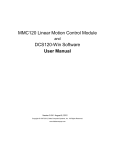
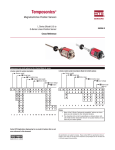
December 1, 2010
Rapid Controls
SAB-E-SSI
User Manual
The SAB-E-SSI outputs SSI position information based on either a PWM or Start/Stop magnetostrictive
transducer or an analog voltage signal, depending on the model of SAB-E-SSI. The SSI output is designed
to be compatible with MTS and other magnetostrictive sensors with SSI protocol output.
Both models respond to the SSI clock signal with a scaled position directly related to the input data. This
position data can be offset or scaled by the user.
The SAB-E-SSI-R uses a high precision time-to-digital conversion to achieve up to 5 micron resolution
from Start/Stop or PWM sensors, without recirculation.
A remote control mode allows the SSI value to be controlled directly by a host device. When in this mode,
the host can set the SSI output value using RS-232 or RS-485 serial commands.
1 of 16
December 1, 2010
Features
Model SAB-E-R
• Measures a Start/Stop or PWM output magnetostrictive sensor with up to 5 micron resolution
• Green LED indicates sensor function
Model SAB-E-A
• Measures one channel of uni-polar or bipolar voltage input, +/- 10V or 0 to 10V
• 16-bit analog to digital converter
• Expanded input range (10.26V) prevents saturation
• Instrumentation amplifier and precision reference provided
All Models
• Outputs one channel of 24 or 25 bit SSI output
• Fast output supports up to 500 kHz clock speed
• Dip Switch programmable output resolution
• 24 or 25 bit mode programmable settable via Dip Switch
• Gray code or binary SSI output is settable via Dip Switch
• Blinking Red LED indicates good operation of processor and SSI update rate
• Green LED indicates SSI activity
• Convenient screw terminal connections
Specifications
Model SAB-E-R
• One channel of Start/Stop or PWM transducer measurement
• PWM Sensor can be free running (internally interrogated) and asynchronous to the converter
• Start/Stop and PWM measurement resolution is selectable via dip switch as 5, 10, 20, or 50 microns or
.00025, .0005, .001 or .002 inches
• 5 uS hold off period for Start/Stop sensors
• The SSI update rate can be as fast as 4 kHz
• Minimum time between SSI interrogation is 250 uS or conversion time plus 50 uS, whichever is greater
Model SAB-E-A
• One channel of DC voltage input with differential or single ended input
• Jumper selectable input ranges: include +/- 10 V 0 to 10 V +/-5 V and 0 to 5 V
• Expanded input range is –10.25 to 10.25 VDC or 0 to 10.25V
• Optional input gain of up to 5000 with Instrumentation Amplifier
• 16 bit A/D converter: 0.000153 V resolution in unipolar mode or 0.00031 V resolution in bipolar mode
• Minimum time between SSI clock trains 250 uS
All Models
• One channel of 24 or 25 bit binary or Gray code SSI transducer emulation
• Maximum SSI clock frequency of 500 kHz
• Maximum SSI update rate of 4 kHz
• Power requirements: 7.5 – 26 VDC at <300 mA (optional features may consume more current)
• Enclosure is 4.64 inches deep x 5.31 high x 1.77 wide (118 x 135 x 46 mm)
• Enclosure occupies 1.77 inches (45 mm) of DIN rail space
Ordering Information
Model
Input
Output
Channels
SAB-E-SSI-R
Start/Stop or PWM (differential RS422)
SSI (differential RS422)
1
SAB-E-SSI-R-2
Start/Stop or PWM (differential RS422)
SSI (differential RS422)
2
SAB-E-SSI-A
Analog Voltage (+/- 10V or 0-10V)
SSI (differential RS422)
1
SAB-E-SSI-A-2
Analog Voltage (+/- 10V or 0-10V)
SSI (differential RS422)
2
2 of 16
December 1, 2010
Contents
Ordering Information........................................................................................................................................2
Contents............................................................................................................................................................3
General Operation.............................................................................................................................................4
SAB-E-R Specific Operation........................................................................................................................5
SSI Value..................................................................................................................................................5
SSI Timing................................................................................................................................................5
SAB-E-A Specific Operation........................................................................................................................6
SAB-E-A SSI value..................................................................................................................................6
SAB-E-A SSI Timing...............................................................................................................................6
Status.................................................................................................................................................................6
System LED..................................................................................................................................................6
Input LED.....................................................................................................................................................6
SSI LED........................................................................................................................................................6
Status Relay..................................................................................................................................................6
Setup.................................................................................................................................................................7
SAB-E-A Specific Setup...............................................................................................................................8
Analog Input Source Selection.................................................................................................................8
Analog Input Scaling................................................................................................................................8
Analog Input Expanded Range.................................................................................................................9
Setup Mode.................................................................................................................................................10
G - Gradient............................................................................................................................................10
H - Holdoff.............................................................................................................................................10
S - Scale..................................................................................................................................................11
A - Sensor data IS or IS NOT synchronized to SSI clock......................................................................11
F - Factory Defaults................................................................................................................................11
E - Save to EEPROM.............................................................................................................................11
V - View Sensor Position........................................................................................................................11
Remote Control...............................................................................................................................................11
Remote Control protocol............................................................................................................................12
Jumpers...........................................................................................................................................................12
Jumper X2...................................................................................................................................................12
Jumper X3...................................................................................................................................................12
Jumper X4 (SAB-E-A)...............................................................................................................................12
Jumper X5 (SAB-E-A)...............................................................................................................................12
Jumper X6, X7 and X8 (SAB-E-A)............................................................................................................13
Connections....................................................................................................................................................13
Connector JP1 (Communications DB9).....................................................................................................13
Connector JP2 (Start/Stop or PWM Sensor connector SAB-E-R).............................................................13
Connector JP2 (Analog input connector SAB-E-A)...................................................................................13
Connector JP3 (SSI emulation connector)..................................................................................................13
Connections for SAB-E-A-SSI with isolated analog sensor ..........................................................................14
Connections for SAB-E-R-SSI with isolated sensor.......................................................................................15
Enclosure........................................................................................................................................................16
3 of 16
December 1, 2010
General Operation
The SAB-E module transmits a binary or Gray Code SSI data value in response to an SSI
interrogation from a host controller. Under normal operation, or Sensor Conversion mode, the value
transmitted in response is determined by measuring the Start/Stop, PWM or Analog sensor and then scaling
it using the gradient, desired SSI resolution and a user-configured scalar. In Remote Control Slave mode,
the SSI value output is directly controlled by a host device over the RS232/485 serial link and sensor
measurement data is not used.
At power-on the board reads dip switch 7 to determine the operational mode, Sensor Conversion
(SW 7 OFF) or Remote Control Slave (SW 7 ON). In Sensor Conversion mode the module immediately
sends version and setup information over the RS232 port at 9600 baud. The module beings monitoring the
SSI clock lines, waiting for an SSI interrogation. The sensor will be interrogated during this period. If
possible, the sensor conversion process will be synchronized with the start of the SSI clock. This data will
be used for the next SSI output value.
In the Slave Mode the module responds to serial commands from the host. The slave mode baud
rate is determined in Setup Mode. The SSI value is determined by the commands from the host.
If dip switch 8 is ‘ON’ the module will enter Setup Mode, allowing baud rate and other items to be
changed.
Figure: SSI Timing Diagram
4 of 16
December 1, 2010
SAB-E-R Specific Operation
SSI Value
For the SAB-E-R module the value transmitted in response to the SSI clock is determined by the
transducer measurement resolution and the entered scale value. The PWM or Start/Stop transducer is
measured with the resolution requested by dip switches 3, 4 and 5 and the entered sensor Gradient. The
value measured is multiplied by the scale value before it is output. If for example the scale is 0.5 then the
SSI output will be ½ of the measured value. The default scale is 1.0.
SSI Timing
For the SAB-E-R module the interrogation of the sensor occurs on the leading edge of the SSI
clock train. The resultant value will be loaded on the trailing edge of the next SSI clock train. If the
measurement takes longer than the SSI update time the last completed measurement will be resent.
Measurements may overlap the SSI update times. PWM gates may be asynchronous, or internally
interrogated.
5 of 16
December 1, 2010
SAB-E-A Specific Operation
SAB-E-A SSI value
For the SAB-E-A module the value transmitted in response to the SSI clock is determined by the
input voltage and the scale value. The analog input is measured with a resolution of 1/65536 yielding a
digitized value in the range 0 to 65535. The value measured is then multiplied by the scale value before it
is output. If, for example, the scale is 0.5 the maximum SSI output will be ½ of 65535 or 32768 and the
value of each SSI count will be doubled. The scale value can be greater than 1.0, but with a resultant loss in
resolution. For example, a scale of 2.0 will yield a maximum SSI count of 131070. The default scale is 1.0.
SAB-E-A SSI Timing
For the SAB-E-A module the SSI clock trains must be separated by 250 usec.
Status
The SAB-E-SSI has three LEDs for status indication, one red and two green. The red LED is the
System LED. The first green LED is the Input LED and second is the SSI LED.
System LED
The red LED, or System LED, blinks during normal operation. The blink rate indicates the update
rate of the SSI clock. After every 500 occurrences of an SSI interrogation, the LED will change state, from
lit to dark or from dark to lit. An SSI update frequency of 1kHz will result in the red LED blinking at a rate
of 1 Hz. In setup mode, the red LED will be lit solid. If no SSI clock is detected, the red LED will flash
very quickly.
Input LED
The first green LED, the Input LED, indicates the status of the input sensor or voltage source. A lit
Input LED indicates that the input sensor is operating correctly. A dark Input LED indicates a problem with
the input sensor, such as a missing magnet.
The Input LED status is also appended to the “back porch” of the SSI data stream with a low
indicating good sensor status and a high indicating a fault. The “back porch” is the time period following
the least significant bit and ending 25 microseconds after the last clock. A controller can sample the data at
this time to determine the condition of the sensor. This operation is required by some Rockwell motion
controllers.
SSI LED
The second green LED, the SSI LED, shows the status of the SSI interface. If the Status LED is lit,
the SSI interface is being interrogated. A dark Status LED indicates that no activity has been detected on the
SSI clock lines.
Status Relay
A pair of relay contacts are provided to indicate sensor status to a host device. These pins are open
if the sensor is not good and closed if the green Sensor Status led is lit. These contacts are across JP1-5 and
6. The sensor is always considered good for the SAB-E-A.
6 of 16
December 1, 2010
Setup
The dip switches are used to configure the SAB-E-SSI, or to enter Setup Mode. The dip switches
are sampled when power is applied, so power must be cycled to make changes effective. When dip switch 8
is ‘ON’ the device will enter Setup Mode. When dip switch 8 is OFF the device will enter Normal
Operation Mode.
.
Switches 1 and 2 of dip switch S1 are used to select the SSI emulation as follows:
S1-1
S1-2
SSI Emulation
OFF
OFF
24 Bit Binary
ON
OFF
25 Bit Binary
OFF
ON
24 Bit Gray Code
ON
ON
25 Bit Gray Code
Switches 3, 4 and 5 (SAB-E-R only) of dip switch S1 are used to select the transducer
measurement resolution, which is the value of the Least Significant Bit in the SSI data train. The values
shown are for a single recirculation. If a PWM sensor is used, the values shown will be divided by the
number of recirculations set in the sensor. I.E with switches 3, 4 and 5 off and a 2 recirculation sensor
attached the actual resolution will be 2.5 microns.
S1-3
S1-4
S1-5
Measurement resolution
Per Inch Scale = 1.0
OFF
OFF
OFF
5 microns
5080
ON
OFF
OFF
10 microns
2540
OFF
ON
OFF
20 microns
1270
ON
ON
OFF
50 microns
508
OFF
OFF
ON
0.00025 inch
4000
ON
OFF
ON
0.0005 inch
2000
OFF
ON
ON
0.001 inch
1000
ON
ON
ON
0.002 inch
500
In Sensor Measurement Mode, the actual value transmitted over the SSI data lines in response to the SSI
clock , is determined by several dip switch and setup items. If the correct gradient is entered and the scale
is 1.0 a change of magnet position of 1 inch should produce a change in SSI output value of (1 / resolution).
Switch 6 (SAB-E-R only) indicates the type of Transducer interface that is being measured
S1-6
OFF
ON
Sensor Interface
Start/Stop
PWM
Switch 7 determines the source of the SSI value. When switch 7 is ‘OFF’ the SSI value that is output is
determined by the sensor and the associated scaling. If switch 7 is ‘ON’ the SSI value is controlled by serial
commands from a remote host device. See section Remote Control.
S1-7
Remote Control
OFF
SSI value is sensor value
ON
SSI value is controlled by serial
commands from Remote Host
Switch 8 is used to force the Emulator into Setup mode at power on.
S1-8
OFF
ON
Setup Mode
Normal Operation
In Setup Mode
7 of 16
December 1, 2010
SAB-E-A Specific Setup
Analog Input Source Selection
The SAB-E-A module has a choice of two analog inputs: high level single ended or differential
instrumentation amplifier. Jumper X4 selects which of these inputs is presented to the A/D converter. When
Jumper X4 is installed 2-3 then the analog value at JP2 pin 1 is connected directly to the A/D converter
filter without amplification. It is referenced to pin 2, analog common.
When Jumper X4 is installed 1-2 then the output of the instrumentation amplifier is connected to
the A/D converter filter input. The instrumentation amplifier allows low level signals to be amplified and
has a differential input for noisy environments. When Jumper X5 is removed the gain of the instrumentation
amplifier is 1.0. allowing a differential input for high level signals. When jumper X5 is installed the GAIN
pot can be adjusted for gains from 2 to 5000. When using a differential analog input connect the DC
common of the source to JP2 –2 analog common.
Analog Input Scaling
The SAB-E-A module converts the analog input to a count value based on the A/D converter range
jumpers. The range jumpers are set to +/- 10V at the factory but can be changed to accommodate 0 to 10V.
The A/D converter divides the input range into 63858 parts, multiples this value by the scale and then
presents these counts on the SSI interface as SSI counts. The table below gives the values for the two
common ranges supported.
INPUT RANGE
-10V to +10V
0 to 10V
X6
1-2
2-3
X7
1-2
2-3
X8
1-2
2-3
Maximum usable
-10.27V to +10.27V
0 to 10.27V
8 of 16
MilliVolts / SSI Count (scale = 1.0)
0.31332216
0.15666108
December 1, 2010
To calculate what the value of each SSI count is in the units of the input sensor divide the sensors full scale
range in units by 63858. Remember that the full-scale range is the number of units from –10V to +10V or 0
to 10V depending on the sensor and the A/D converter input range.
Example 1: (scale = 1.0)
Assume you have a 100 mm sensor that outputs –10V fully retracted and +10V fully extended . You must
use the –10V to +10V A/D range and the Units per SSI count will be (100mm / 63832 =
0.001565975mm/SSI count.
Example 2: (scale = 1.0)
Assume you have a 750 PSI pressure sensor that outputs 0V at 0 PSI and +10V at 750 PSI You can use the
0V to +10V range and the units per SSI count will be (750 PSI/63858) = 0.011745 PSI/SSI count.
Example 3: (same as example 2 but the scale is set to correct to an even number of PSI/SSI count)
Assume that in example 2 you would like each SSI count to have a value of 1/100 PSI. You can accomplish
this by setting the scale. To obtain the needed scale, divide the PSI/SSI count obtained in the example 2
calculations by the desired PSI/SSI count. 0.011745/ 0.01 = 1.17448. Enter this value as the scale. The
measurement resolution will not be increased, but the values output on the SSI data lines are multiplied by
the scale before being output.
Analog Input Expanded Range
The voltage input to the module is actually scaled down by a factor of 0.974 before being presented to the
A/D converter. This is done to allow for a small amount of inaccuracy in the placement of linear sensors in
hydraulic cylinders. The A/D converter saturates when it’s input reaches –10V or +10V preventing a
change in feedback beyond these values. By scaling the input down the effective range is increased to +/10.26V. When you use the 0 to 10V range the range is limited to 0 to 10.26 volts. The range is not
increased below 0 but is increased above 10V. A slight loss in measurement resolution is another result of
the expanded range.
9 of 16
December 1, 2010
Setup Mode
Setup Mode allows setting of the gradient variable, the update time, the remote control baud rate and
viewing of the sensor data via a terminal or terminal emulator such as HyperTerminal. Turn Dip Switch 8
ON and then power cycle the unit to enter Setup Mode. The unit will respond with a Software version
banner on the serial port at 9600 baud, 8 bits, No parity and 1 stop bit. A menu will prompt for the setup
values. After changing the values you must save them to the EEPROM or they will be lost when the SAB-ESSI is powered off. Turn Switch 8 OFF and then power cycle the unit. The new value will then be in effect.
The SAB-E-A Setup Menu:
Rapid Controls ANALOG to SSI Converter Nov 21 2006
SSI length: 25 bit
SSI format: binary
Sensor is Analog
Setup Mode for Rapid Controls Analog to SSI converter
Select item to change
B - Remote Control Comm Baud Rate
9600
N - Remote Control Node ID 1
L - Analog Filter length 1
S - Scale 1.0000000
V - View sensor position
E - Save to EEPROM
F - Factory Defaults
Q - Quit Menu
The SAB-E-R Setup Menu:
Rapid Controls RPM to SSI Converter Nov 21 2006
SSI length: 25 bit
SSI format: binary
SSI Resolution: 0.005 mm
Sensor is Start/Stop
Sensor Gradient is: 9.0000000
Sensor Scale is: 1.0000000
Setup Mode for Rapid Controls RPM to SSI converter
Select item to change
B - Remote Control Comm Baud Rate
9600
N - Remote Control Node ID 1
G - Gradient 9.0000000
H - Holdoff
7
A - Sensor data IS synchronized to SSI Clock
S - Scale 1.0000000
V - View sensor position
E - Save to EEPROM
F - Factory Defaults
Q - Quit Menu
G - Gradient
The gradient would typically be the value read from the sensor housing and is used to calibrate the module
to the sensor. The default value is 9.0 microseconds per inch. This item is not visible on the SAB-E-A
module.
H - Holdoff
The Holdoff time is the time when gate pulses are blocked from the sensor immediately after the
interrogate signal is issued. Occasionally sensors may have a sporadic or false gate which can be blocked
by extending the holdoff time. A high holdoff value can make a sensor appear not to work when the magnet
is close to the head.
10 of 16
December 1, 2010
The Holdoff function is not used when the PWM mode is selected.
S - Scale
The scale is applied to the sensor position data before it is presented to the SSI output. The scale allows the
output value to be adjusted for units other than the values selected by the dip switch or to adjust for
recirculations. For example if you were using a PWM sensor with 4 recirculations you could apply a scale
of 0.25 to adjust the output to 1 recirculation. The default value of the scale is 1.0.
A - Sensor data IS or IS NOT synchronized to SSI clock
This setting an be used to optimize the availability of the converted data to the SSI clock. The data resulting
from the conversion of the start/stop or PWM sensor can be loaded as soon as it’s available (not
synchronized) or wait for the end of the next SSI clock (synchronized). Loading it immediately will make it
available for the next SSI clock train to read. However, in the event that the time required to convert the
sensor data is longer than the time between SSI clock trains or if the sensor is an asynchronous PWM sensor
the data load must be synchronized to the SSI clock to avoid loading the data while the SSI clock is active.
The time required to convert the data for a Start/Stop sensor is approximately 9 * the sensor length in
inches. The required for a PWM sensor is 9 * the sensor length in inches * the number of recirculations. If
this time exceeds the time between SSI clock trains or the PWM signal is asynchronous (internally
interrogated) then the setting should be set to IS synchronized. The default value is ‘IS’ synchronized.
F - Factory Defaults
Returns all setup values to the factory defaults.
E - Save to EEPROM
Saves the current values to the EEPROM. Any setup changes will be lost once power is cycled until saved.
V - View Sensor Position
Use this item to see the converted value of the sensor. The numeric value printed is the value loaded into
the SSI transfer register. A change of 1 count represents a change of 1 count in the emulated SSI value. The
printed value is scaled using the scale, resolution and gradient settings from the dip switch and setup items.
Remote Control
When dip switch 7 is ‘ON’ the device is in Remote Control mode and is controlled by commands from the
serial port. A sensor is not necessary in this mode. When the Remote Control dip switch is on, the serial
port is configured for the baud rate defined in setup mode and the module is silent (the status messages are
not printed) at power on. It responds only to valid commands to its node id.
The Baud Rate for Remote Control is determined in Setup Mode.
11 of 16
December 1, 2010
Remote Control protocol
Remote Control commands consist of the ASCII Start of Message (‘$’) character followed by the ASCII
Node ID (‘1’,’2’,’3’,’4’,’5’,’6’,’7’,’8’ or ‘9’) followed by the command and optional data followed by the
message termination char(Carriage Return ASCII 0xd).
The response to a good command message is the ‘*’ character followed by the carriage return (ASCII 0xd).
Response to an incorrect command will be a ‘?’ followed by the carriage return (ASCII 0xd).
The Mode command (‘M’) determines the SSI mode and data length:
A ‘B’ character anywhere in the message will select binary operation
A ‘G’ character anywhere in the message will select Gray Code operation
The numeric values “24” or “25” must precede or follow the ‘B’ or ‘G’ characters.
$1MB24 will result in 24 bit binary operation for Node 1.
$3M25G will result in 25 bit Gray Code operation for Node ID 3
The Mode command (‘P’) determines the value if the SSI data:
A numeric value followed by the carriage return is interpreted as a decimal value.
A ‘H’ character preceding the hexadecimal numeric value followed by the carriage return is interpreted as a
hexadecimal value.
$1P210000 will result in a data value output of 210,000 for Node ID 1.
$2PH210000 will result in a data value output of 210,000H (2,162,688 decimal) for Node ID 2.
The Version command ‘V’ will return an ASCII string with the version of the software.
example:
$1V will return:
*Rapid Controls RPM to SSI Converter Jan 10 2006
Jumpers
Jumper X2
This jumper selects the serial communications format.
X2 1-2 RS485
X2 2-3 RS232
Jumper X3
This jumper connects the RS485 line termination resistors. Install 1-4 and 2-3 for the last board in
a series of RS485 configured boards to provide line termination.
X3 1-2 Connects RS485 – to +5V pull up terminator
X3 3-4 Connects RS485 + to ground pull down terminator
Jumper X4 (SAB-E-A)
This jumper selects the Analog input to the A/D converter
X4 1-2 The output of the Instrumentation Amplifier is presented to the A/D converter
X4 2-3 The high level input from JP2-1 is presented to the A/D converter
Jumper X5 (SAB-E-A)
Jumper X5 allows gain adjustments on the Instrumentation Amplifier
X5 1-2 The gain is adjustable from 2 to 5000 using the Gain potentiometer.
X5 Removed The gain is fixed at 1.0
12 of 16
December 1, 2010
Jumper X6, X7 and X8 (SAB-E-A)
These jumpers select the A/D converter full scale input voltage range. +/- 10V is the factory set
range but use the 0 to 10V setting for uni-polar input. Jumpers X6, X7, and X8 must be set identically for
correct operation.
Range
X6
X7
X8
+/- 10V
1-2
1-2
1-2
0 to 10V
2-3
2-3
2-3
The instrumentation amplifier gain can be used to accommodate other ranges.
Connections
Connector JP1 (Communications DB9)
JP1 – 1
JP1 – 2
JP1 – 3
JP1 – 4
JP1 – 5
JP1 – 6
JP1 – 7
JP1 – 8
JP1 – 9
RS485 RS232 Receive from host
RS232 Transmit to host
DTR in (Used only for in circuit programming)
DC Common
N/C
N/C
N/C
RS485 +
Communications cable pinout
SAB-E Signal
Tx Data RS232
Rx Data RS232
Gnd
SAB-E JP1
3
2
5
PC DB9
2
3
5
Connector JP2 (Start/Stop or PWM Sensor connector SAB-E-R)
JP2 – 1
JP2 – 2
JP2 – 3
JP2 – 4
JP2 – 5
Sensor common (Isolated from the JP3 and JP4 connectors
Interrogate + to sensor
Interrogate – to sensor
Gate + from sensor
Gate – from sensor
Connector JP2 (Analog input connector SAB-E-A)
JP2 – 1
JP2 – 2
JP2 – 3
JP2 – 4
JP2 – 5
High level analog Input
Analog common
Instrumentation Amplifier – input
Instrumentation Amplifier + input
+10V Reference Output
Connector JP3 (SSI emulation connector)
JP3 – 1
JP3 – 2
JP3 – 3
JP3 – 4
JP3 – 5
JP3 – 6
JP3 – 7
JP3 – 8
Ch0 SSI data out +
Ch0 SSI data out –
Ch0 SSI clock in +
Ch0 SSI clock in –
Status relay contact 2 (closed contacts indicate good sensor)
Status relay contact 1
+ 7.5 to +27 Volts DC to power the board
DC Common
13 of 16
December 1, 2010
Connections for SAB-E-A-SSI with isolated analog sensor
14 of 16
December 1, 2010
Connections for SAB-E-R-SSI with isolated sensor
15 of 16
December 1, 2010
Enclosure
The SAB-E-SSI is mounted in a DIN rail mounted enclosure, containing one or two SAB-E-SSI
boards. The enclosure is 4.64 inches deep x 5.31 high x 1.77 wide, and uses 1.8 inches of DIN rail space.
16 of 16