1
SERIES 7700
INTELLIGENT LDT INTERFACE MODULE
USER'S MANUAL
Catalog Number 7700-195M
This manual is written to explain the
operation of the following AMCI Modules
for the Allen-Bradley 1771 I/O:
7751
7752
General Information
Important User Information
The products and application data described in this manual are useful in a wide variety of
different applications. Therefore, the user and others responsible for applying these products
described herein are responsible for determining the acceptability for each application. While
efforts have been made to provide accurate information within this manual, AMCI assumes no
responsibility for the application or the completeness of the information contained herein.
UNDER NO CIRCUMSTANCES WILL ADVANCED MICRO CONTROLS, INC. BE
RESPONSIBLE OR LIABLE FOR ANY DAMAGES OR LOSSES, INCLUDING INDIRECT OR
CONSEQUENTIAL DAMAGES OR LOSSES, ARISING FROM THE USE OF ANY
INFORMATION CONTAINED WITHIN THIS MANUAL, OR THE USE OF ANY PRODUCTS
OR SERVICES REFERENCED HEREIN.
Throughout this manual the following two notices are used to highlight important points.
! W A R N IN G
WARNINGS tell you when people may be hurt or equipment may be damaged if the
procedure is not followed properly.
! C A U TIO N
CAUTIONS tell you when equipment may be damaged if the procedure is not
followed properly.
No patent liability is assumed by AMCI, with respect to use of information, circuits,
equipment, or software described in this manual.
The information contained within this manual is subject to change without notice.
Standard Warranty
ADVANCED MICRO CONTROLS, INC. warrants that all equipment manufactured by it will
be free from defects, under normal use, in materials and workmanship for a period of [1] year.
Within this warranty period, AMCI shall, at its option, repair or replace, free of charge, any
equipment covered by this warranty which is returned, shipping charges prepaid, within one year
from date of invoice, and which upon examination proves to be defective in material or
workmanship and not caused by accident, misuse, neglect, alteration, improper installation or
improper testing.
The provisions of the "STANDARD WARRANTY" are the sole obligations of AMCI and
excludes all other warranties expressed or implied. In no event shall AMCI be liable for incidental
or consequential damages or for delay in performance of this warranty.
Returns Policy
All equipment being returned to AMCI for repair or replacement, regardless of warranty status,
must have a Return Merchandise Authorization number issued by AMCI. Call (860) 585-1254
with the model number and serial number (if applicable) along with a description of the problem.
A "RMA" number will be issued. Equipment must be shipped to AMCI with transportation
charges prepaid. Title and risk of loss or damage remains with the customer until shipment is
received by AMCI.
24 Hour Technical Support Number
24 Hour technical support is available on this product.
For technical support, call (860) 583-7271.
ADVANCED MICRO CONTROLS INC.
Series 7700 Table of Contents
General Information
Important User Information ..................................................................
Standard Warranty ................................................................................
Returns Policy .......................................................................................
24 Hour Technical Support Number.......................................................
Inside Front Cover
Inside Front Cover
Inside Front Cover
Inside Front Cover
Chapter 1 Introduction to the 7700 LDT Interface Module
The Series 7700 LDT Interface Modules ......................................................................
Series 7700 Family Members ..........................................................................................
Magnetostrictive LDT Description..................................................................................
7700 Functions and Parameters .....................................................................................
Functions ......................................................................................................... 1-3
Scaling Parameters .......................................................................................... 1-3
Set-up Parameters ........................................................................................... 1-3
Application Notes ..........................................................................................................
1-1
1-1
1-2
1-3
1-4
Chapter 2 Series 7700 Module Description
Front Panel Description ................................................................................................. 2-1
Function and Parameter Displays .................................................................................. 2-2
Position Data Display ..................................................................................... 2-2
Velocity Data Display ..................................................................................... 2-2
Count Direction Parameter ............................................................................. 2-2
Full Scale Length Parameter ........................................................................... 2-3
Full Scale Count Parameter ............................................................................ 2-3
Position Offset Parameter ............................................................................... 2-3
Setup Parameter Display ................................................................................. 2-4
LDT Type Parameter ...................................................................................... 2-4
DPM Recirculations Parameter ....................................................................... 2-4
Measurement Unit Parameter .......................................................................... 2-5
LDT Gradient Parameter ................................................................................. 2-5
Decimal Point Parameter ................................................................................ 2-5
Preset Value Parameter ................................................................................... 2-6
Speed Average Parameter ............................................................................... 2-6
Data Format Parameter ................................................................................... 2-6
Transfer Type Parameter ................................................................................. 2-6
Status Indicators ............................................................................................................. 2-7
Error Class 1: Transducer Fault ..................................................................... 2-7
Error Class 2: E2PROM Fault ........................................................................ 2-7
Error Class 3: RAM Fault .............................................................................. 2-7
Error Class 4: Power Supply Shut-down Fault .............................................. 2-8
Overflow/Underflow Indication ...................................................................... 2-8
Program Switch .............................................................................................................. 2-9
Keyboard Description .................................................................................................. 2-10
Transducer Input Connector ........................................................................................ 2-11
Fuse Replacement ........................................................................................................ 2-11
Specifications ............................................................................................................... 2-12
ADVANCED MICRO CONTROLS INC.
i
Series 7700 Table of Contents
Chapter 3 Installation
Power Requirements ......................................................................................................
Installing the Module .....................................................................................................
Keying Bands .................................................................................................................
Compatible Transducers ................................................................................................
Temposonics II DPM Setup ...........................................................................................
Transducer Mounting .....................................................................................................
Grounding Clamp ...........................................................................................................
Cable Installation ...........................................................................................................
3-1
3-1
3-1
3-2
3-2
3-2
3-2
3-3
Chapter 4 Keyboard Programming
Conventions ...................................................................................................................
Scaling Parameters .........................................................................................................
Count Direction ............................................................................................... 4-1
Full Scale Length ............................................................................................ 4-2
Full Scale Count .............................................................................................. 4-2
Position Offset ................................................................................................ 4-2
Setup Parameters ............................................................................................................
LDT Type ........................................................................................................ 4-3
DPM Recirculations ........................................................................................ 4-4
Measurement Unit ........................................................................................... 4-4
LDT Gradient .................................................................................................. 4-5
Decimal Point Position .................................................................................... 4-5
Preset Value .................................................................................................... 4-5
Speed Average ................................................................................................ 4-6
Data Format ..................................................................................................... 4-6
Transfer Type .................................................................................................. 4-6
Auto Preset Feature ........................................................................................................
4-1
4-1
4-3
4-7
Chapter 5 AMCI Module Addressing
Module Addressing ........................................................................................................
Definition of Terms .......................................................................................................
I/O Rack .......................................................................................................... 5-1
I/O Group ........................................................................................................ 5-1
Slot Addressing ............................................................................................... 5-1
Addressing a Block Transfer Module ............................................................................
Addressing a Single Transfer Module ...........................................................................
Addressing Examples .....................................................................................................
Restrictions and Warnings .............................................................................................
5-1
5-1
5-2
5-3
5-3
5-4
Chapter 6 PLC-2 Block Transfer Instructions
Overview ........................................................................................................................
Data and Module Address ..............................................................................................
Block Length ..................................................................................................................
File Address ...................................................................................................................
Enable (EN) and Done (DN) Bits ..................................................................................
ii
6-1
6-1
6-1
6-2
6-2
ADVANCED MICRO CONTROLS INC.
Series 7700 Table of Contents
Chapter 6 PLC-2 Block Transfer Instructions (cont’d)
Programming Example .................................................................................................. 6-3
PLC-2 Restrictions and Warnings ................................................................................. 6-4
Chapter 7 PLC-3 Block Transfer Instructions
Overview ........................................................................................................................
Module Address .............................................................................................................
Data Address ..................................................................................................................
File Length .....................................................................................................................
Control File ....................................................................................................................
Latch Enable (LE), Error (ER), and Done (DN) Bits ....................................................
Programming Example ..................................................................................................
PLC-3 Restrictions and Warnings .................................................................................
7-1
7-1
7-1
7-1
7-2
7-2
7-3
7-4
Chapter 8 PLC-5 Block Transfer Instructions
Overview ........................................................................................................................
Module Address .............................................................................................................
Control Block .................................................................................................................
Data File .........................................................................................................................
File Length .....................................................................................................................
Continuous Parameter ....................................................................................................
Enable (EN), Error (ER), and Done (DN) Bits ..............................................................
Programming Example ..................................................................................................
PLC-5 Restrictions and Warnings .................................................................................
8-1
8-1
8-1
8-1
8-1
8-2
8-2
8-3
8-4
Chapter 9 Series 7700 Data Format
Block Transfer Data Format .......................................................................................... 9-1
Status Bits ....................................................................................................... 9-1
Notes ............................................................................................................... 9-1
Hardware Errors .............................................................................................. 9-2
Software Errors ............................................................................................... 9-2
Single Transfer Data Format .......................................................................................... 9-2
Notes and Restrictions .................................................................................... 9-2
Chapter 10 Programming Instructions and Error Codes
Programming Structure ................................................................................................ 10-1
Program Instructions .................................................................................................... 10-2
Module Instructions ..................................................................................................... 10-2
Transducer Instructions ............................................................................................... 10-3
Read Status Instructions ............................................................................................... 10-6
Read Status Data Format ............................................................................................. 10-8
Error Codes .................................................................................................................. 10-9
Hardware Errors ............................................................................................ 10-9
Software Errors ........................................................................................... 10-10
ADVANCED MICRO CONTROLS INC.
iii
Series 7700 Table of Contents
Prints
B1068 Rev. A
A1071
B1241
B1242
B1178
B1177
iv
Series 1700 Outline Drawing ................................................................
GC-1 Grounding Clamp (7700) ...........................................................
C1TL-(x) Transducer Cable Drawing ...................................................
C2TL-(x) Transudcer Cable Drawing ...................................................
Temposonics 1 Axis Wiring Diagram ...................................................
Temposonics 2 Axis Wiring Diagram ...................................................
P-1
P-2
P-3
P-4
P-5
P-6
ADVANCED MICRO CONTROLS INC.
Series 7700 List of Figures
Chapter 1 Introduction to the 7700 LDT Interface Module
Fig 1.1 Typical Magnetostrictive LDT ........................................................................ 1-2
Fig 1.2 7700 Application ............................................................................................. 1-4
Chapter 2 Series 7700 Module Description
Fig 2.1 7700 Front Panel .............................................................................................. 2-1
Fig 2.2 Position Display ............................................................................................... 2-2
Fig 2.3 Velocity Display .............................................................................................. 2-2
Fig 2.4 Count Direction ............................................................................................... 2-2
Fig 2.5 Full Scale Length ............................................................................................. 2-3
Fig 2.6 Full Scale Count .............................................................................................. 2-3
Fig 2.7 Position Offset ................................................................................................. 2-3
Fig 2.8 Setup Display ................................................................................................... 2-4
Fig 2.9 LDT Type ........................................................................................................ 2-4
Fig 2.10 DPM Recirculations ....................................................................................... 2-4
Fig 2.11 Measurement Unit .......................................................................................... 2-5
Fig 2.12 LDT Gradient ................................................................................................. 2-5
Fig 2.13 Decimal Point ................................................................................................. 2-5
Fig 2.14 Preset Value .................................................................................................... 2-6
Fig 2.15 Speed Average ................................................................................................ 2-6
Fig 2.16 Data Format .................................................................................................... 2-6
Fig 2.17 Transfer Type ................................................................................................. 2-6
Fig 2.18 Transducer Fault ............................................................................................. 2-7
Fig 2.19 E2PROM Fault ................................................................................................ 2-7
Fig 2.20 P. S. Fault ....................................................................................................... 2-8
Fig 2.21 Position Overflow ........................................................................................... 2-8
Fig 2.22 Position Underflow ......................................................................................... 2-8
Fig 2.23 Program Switch .............................................................................................. 2-9
Fig 2.24 Keyboard Description ................................................................................... 2-10
Fig 2.25 Transducer Input Connector Part Numbers .................................................. 2-11
Fig 2.26 Power Fuse ................................................................................................... 2-11
Chapter 3 Installation
Fig 3.1 Module Installation .......................................................................................... 3-1
Fig 3.2 GC-1 Grounding Clamp Installation ............................................................... 3-2
Chapter 5 AMCI Module Addressing
Fig 5.1
Fig 5.2
Fig 5.3
Fig 5.4
Fig 5.5
Fig 5.6
Fig 5.7
2-Slot Addressing ............................................................................................
1-Slot Addressing ............................................................................................
½-Slot Addressing ...........................................................................................
BT Module Address ........................................................................................
Modules' 2-Slot Address ..................................................................................
Modules' 1-Slot Address ..................................................................................
Modules' ½-Slot Address .................................................................................
ADVANCED MICRO CONTROLS INC.
5-1
5-2
5-2
5-2
5-3
5-4
5-4
v
Series 7700 List of Figures
Chapter 6 PLC-2 Block Transfer Instructions
Fig 6.1
Fig 6.2
Fig 6.3
Fig 6.4
Fig 6.5
First Memory Location of T/C Accumulated Register Memory .....................
1700 Module Block Length .............................................................................
2700 Module Block Length .............................................................................
7700 Module Block Length .............................................................................
PLC-2 Programming Example .........................................................................
6-1
6-2
6-2
6-2
6-3
Chapter 7 PLC-3 Block Transfer Instructions
Fig 7.1
Fig 7.2
Fig 7.3
Fig 7.4
1700 Module Block Length .............................................................................
2700 Module Block Length .............................................................................
7700 Module Block Length .............................................................................
PLC-3 Programming Example .........................................................................
7-1
7-2
7-2
7-3
Chapter 8 PLC-5 Block Transfer Instructions
Fig 8.1
Fig 8.2
Fig 8.3
Fig 8.4
1700 Module Block Length .............................................................................
2700 Module Block Length .............................................................................
7700 Module Block Length .............................................................................
PLC-5 Programming Example .........................................................................
8-2
8-2
8-2
8-3
Chapter 9 Series 7700 Data Format
Fig 9.1 Data Format ..................................................................................................... 9-1
Fig 9.2 Hardware Error Format ................................................................................... 9-2
Chapter 10 Programming Instructions and Error Codes
Fig 10.1 7700 Program Instruction Format ................................................................. 10-1
Fig 10.2 Read Status Data Format .............................................................................. 10-8
Fig 10.3 Hardware Error Format ................................................................................ 10-9
Revision History
This revision, 7700-B94M, replaces 7700-293M. It adds information on the AMCI and Balluff
transudcers. It was first released 11/17/94 and coincides with software Rev. 2.
vi
ADVANCED MICRO CONTROLS INC.
Chapter 1 Introduction to the 7700 LDT Interface Module
The Series 7700 LDT Interface Modules
Today's manufacturing processes are becoming more and more complex. Achieving the goals
of lower cost production, higher output, less wasted material, and fewer rejects is important if a
company is to compete in today's global economy. To achieve these goals, programmable
controller systems are being used in more and more applications because of the precise control and
flexibility that such a system provides.
One device that can be use to accurately measure linear distances is the magnetostrictive Linear
Displacement Transducer (LDT). Until the introduction of the Series 7700 Modules, interfacing a
magnetostrictive LDT to a programmable controller system could be a difficult task. One
possibility was to use an external decoder that interfaced to the programmable controller through
an analog or digital input card. Another possibility was the Allen-Bradley Linear Positioning
Module (1771-QB) that could be confusing to use in applications that require only position and
velocity feedback instead of closed loop position control.
Utilizing licensed Allen-Bradley proprietary 1771 I/O interface technology and patents, and the
latest in programmable chip technology, the Series 7700 Modules are direct interfaces between
magnetostrictive LDT's and your A-B programmable controller. The many features of the 7700
Modules make them the most advanced products on the market today.
− Interfaces 1 or 2 AMCI, Balluff or Temposonics™ II LDT's to your programmable controller.
− Communicates with the processor via the Block Transfer Instructions. Block Transfer Read In-
structions give access to position, velocity, and fault diagnostic data while Block Transfer
Write Instructions make the module fully programmable from the backplane.
− Position and velocity resolution fully programmable down to one thousandth of an inch. Other
features include: Position Offset, Count Direction, Auto Preset of position data and many more.
− Self-contained design eliminates the need for an external power supply.
− Extensive diagnostics continuously monitor the transducer and module for fault conditions.
− Sealed display and keyboard for quick program changes during setup or position and velocity
data monitoring.
Series 7700 Family Members
The following make up the line of Series 7700 LDT Interface Modules. Potential future members may have higher resolution, compatibility with different manufacturers of LDT's, or more
than two transducer inputs per module.
− 7751
One transducer interface, 0.001" resolution, ± 100,000 Counts
− 7752
Two transducer interface, 0.001" resolution, ± 100,000 Counts
ADVANCED MICRO CONTROLS INC.
1-1
Chapter 1 Introduction to the 7700 LDT Interface Module
Magnetostrictive LDT Description
Magnetostrictive LDT's rely on a phenomenon known as the Wiedemann Effect. All ferromagnetic metals such as iron and nickel display this phenomenon. A ferromagnetic metal forms a
magnetic field around it whenever it conducts an electrical current. If this field interacts with a
second magnetic field, the metal will physically twist. This twist then travels along the metal in
the same fashion as a ripple in water.
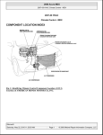
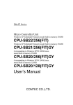
Figure 1.1 shows a typical LDT. The waveguide is a hollow tube made from a ferromagnetic
metal. Threaded through the waveguide is a wire that carries the current pulse from the head of
the LDT. Using a second wire to carry the current pulse instead of the waveguide increases the
accuracy and repeatability of the system. Also located in the head of the LDT, Pickup Coils sense
when the twist in the waveguide, called the Strain Pulse, reaches the head of the LDT.
PR O T EC TIVE
O U T E R C A S IN G
P ER M A N E N T M AG N E T
P IC K U P
C O IL S
M E C H A N IC A L
D AM P E N E R
B IA S
M A G N E TS
CURRENT
W IR E
S T R A IN
P U LS E
Fig 1.1 Typical Magnetostrictive LDT
To determine the position of a permanent magnet along the LDT's length, a current pulse is sent
over the wire contained within the waveguide. This current pulse instantaneously forms a
magnetic field around the waveguide. The waveguide twists where the fields formed by the
current pulse and the magnet intersect. Like a ripple on water, this Strain Pulse travels towards the
head and the end of the LDT at over 9000 feet per second (6000 miles per hour). The strain pulse
that travels towards the head is detected by the pickup coils. The strain pulse that travels toward
the end is absorbed by a mechanical dampener to prevent it from reflecting back to the head and
causing a false signal. The mechanical dampener is the cause of the "dead zone" at the end of the
LDT.
To determine the position of the magnet, it's important to know the speed that the strain pulse
travels along the waveguide. MTS, the manufacturer of Temposonics™ II LDT's, calls this value
the LDT's Gradient and specifies it in µSeconds per inch. Typically, the Gradient has a value of
9.03 but this varies slightly from transducer to transducer. The time it takes the strain pulse to
reach the head of the LDT can be determined by starting a high speed counter when the current
pulse is sent and stopping the counter when the pickup coils sense the strain pulse. The magnets
absolute position from the pickup coil equals the counter time divided by the Gradient value.
1-2
ADVANCED MICRO CONTROLS INC.
Chapter 1 Introduction to the 7700 LDT Interface Module
7700 Functions and Parameters
FUNCTIONS
The 7700 Modules perform two operations. These two operations are called Functions. These
Functions are:
Position Data Function - Gives you information on the position of the LDT's magnet
relative to a zero point.
Velocity Data Function - Gives you information on the velocity of the magnet along the
LDT's shaft.
One or more inputs define each Function. One input is the magnets' absolute position on the
LDT transducer. The other inputs are programmable from the keyboard or the PLC. These
inputs are called Parameters.
SCALING PARAMETERS
Count Direction - Sets the direction, relative to the head of the LDT, that the magnet must
travel to increment the Position Data.
Full Scale Length - Programmable in inches or millimeters, this parameter is the length that
you expect the magnet to travel. Maximum value is 650 inches or 9999 millimeters.
Full Scale Count - This parameter sets the number of counts over the Full Scale Length. The
position resolution is equal to the Full Scale Length ÷ Full Scale Count. Maximum
resolution is 0.001 inches or 0.1 millimeters.
Position Offset - This parameter changes the value of the Position Function without moving
the magnet on the LDT. Use it to set the zero or starting position of the magnet along
the LDT's length.
SET-UP PARAMETERS
These parameters are only available when the module is in Program Mode (See Program
Switch Pg. 2-9 for more information.) These parameters contain information that usually not
changed once the system is running.
LDT Type - This parameter tells the 7700 Module the type of LDT attached to the module. If
you are using Temposonics™ II LDT’s it also specifies the type of Personality Module
installed in its head. Presently, AMCI, Balluff, and Temposonics II LDT’s are supported. When using the 7752 Plug-in card, the two LDTs can be different.
DPM Recirculations - Shown only when a Temposonics II with a DPM module is selected as
the LDT Type, this parameter tells the module how many Recirculations you have set on
the DPM Module. Allowable values are 1, 2, and 4 recirculations.
Measurement Unit - Specifies the measurement unit for all parameters. Set it to the same
measurement system used to specify the length of the LDT, inches or millimeters.
LDT Gradient - This is a LDT calibration parameter. It is the rate at which the return pulse
propagates down the transducer's length. AMCI and Balluff specify it in meters per
second while MTS specifies it in µSeconds per inch.
ADVANCED MICRO CONTROLS INC.
1-3
Chapter 1 Introduction to the 7700 LDT Interface Module
7700 Functions and Parameters (cont'd)
SET-UP PARAMETERS (cont'd)
Decimal Point Position - Used to fix a decimal point on the Position, Full Scale Count,
Position Offset, and Preset Value displays, this parameter is for the convenience of
someone looking at the display. It does not affect the data sent to the processor.
Preset Value - This parameter specifies the value that the Position Function will change to
when the Auto Preset feature is used. Use the Auto Preset feature to set the Position
Function to the correct value when the LDT is at its home or zero position.
Speed Average - Sets the update time of the 7700's Velocity Function. Update time is the
amount of time that the Module totals the change in position of the magnet before
calculating the velocity of the magnet in Counts per Second.
Data Format - Allows you to choose Binary or BCD format for the data being sent to the
PLC.
Transfer Type - Allows you to choose between Block or Single Transfers. (7751 only.)
Application Notes
The Measurement Unit Parameter is in some ways the fundamental parameter of the 7700.
This parameter effects the values that can be entered for the Full Scale Length, Full Scale Count
and LDT Gradient Parameters. Changing the Measurement Parameter resets most other Parameters
to their default values.
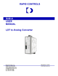
The example below shows how to use the Full Scale Length and Full Scale Count Parameters
to scale the Position and Velocity data to a range of values meaningful to your application. In the
example, you are measuring the amount of liquid on a cylindrical tank.
Tank Capacity
Tank Height
LDT Length
Resolution
= 250 Gallons
= 40 Inches
= 72 Inches
= 0.01 Gallons
7700 Programming
Count Direction: Negative.
F. S. Length:
40 Inches.
F. S. Count:
25000 (250 ÷ 0.01)
Position Offset:
Approx. 20000. Exact Offset
calculated with AUTO PRESET
feature.
LDT Type:
AMCI. (Default)
DPM Recycles:
Not used with AMCI LDT.
Measurement Unit: Inches.
LDT Gradient:
Transducer Dependent.
Decimal Point:
2.
Preset Value:
25000
Speed Average:
240 milliseconds.
Figure 1.2 7700 Application
1-4
ADVANCED MICRO CONTROLS INC.
Chapter 2 Series 7700 Module Description
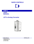
Front Panel Description
The following is a description of the features found on the Series 7700 Modules. Separate
sections of this chapter describes the parts in detail. Unless otherwise noted, all information
presented in this chapter is applicable to all of the modules in the 7700 Series.
Function Display - Used to show the Functions and
Parameters of the 7700 Module. The eight LED indicators
designate what is showing on the alpha-numeric display.
When you are in Program Mode, a blinking digit on the
alpha-numeric display shows the position of the Cursor.
Status Indicators - Indicates the operating condition of the
module.
PRG - Yellow light is on when the module is in Program
Mode.
RUN - Green light is blinking when the module is
operating.
FAULT - Red light is on when there is a fault condition. The
nature of the fault is shown on the alpha-numeric
display.
Program Switch - Located on the top panel, hidden from
view. Used to enable or disable Program Mode. When
enabled, the module is programmable from the keyboard.
Keyboard - Used to examine or change the Functions and
Parameters of the module.
Transducer Input Connector - Connector for the AMCI,
Balluff or MTS Temposonics II Transducers.
Fig 2.1 7700 Front Panel
ADVANCED MICRO CONTROLS INC.
2-1
Chapter 2 Series 7700 Module Description
Function and Parameter Displays
The following displays are available on the 7700 Modules. A brief description of each Function
or Parameter is given to the right of the display. Unless noted, each of the displays is available on
all of the 7700 Modules. Please note that a shaded LED indicator is not lit in the display.
Fig 2.2 Position Display
Position Data Display - This display shows the current position
of the magnet along the LDT's shaft. It's value is based on the
displacement from a programmed zero point.
Maximum/Minimum value is ±99,999. If the Position Data
becomes greater than +99,999 the Position display will change to
“ End ”. If the Position Data becomes less than -99,999 the
Position Display will change to “-End ”. If you are using a 7752
Module, the Position Data Display for the additional transducer
is sequentially available by pressing the [NEXT] Key. The “A”
Indicator LED on the display indicates transducer 1 while the
“B” Indicator LED indicates transducer 2. Position data is
available to the Processor.
Velocity Data Display - This display shows the velocity of the
magnet along the LDT's Shaft in Counts/Second. The time
between updates, which is the time it takes to determine the new
velocity and show it on the display is set by the Speed Average
Parameter. If you are using a 7752 Module, the Velocity Data
Display for the additional transducer is sequentially available by
pressing the [NEXT] Key. The “A” Indicator LED on the display
indicates transducer 1 while the “B” Indicator LED indicates
transducer 2. Velocity data is available to the Processor.
Fig 2.3 Velocity Display
Fig 2.4 Count Direction
2-2
Count Direction Parameter - Sets the direction, relative to the
head of the LDT, that the magnet must travel to increment the
Position Data. When the Count Direction is positive, (“P” on the
display), the Position Function will increment when the magnet
travels away from the LDT's head. When the Count Direction is
negative, (“n” on the display), the Position Function will
increment when the magnet travels towards the LDT's head. If
you are using a 7752 Module, the Count Direction Parameter for
the additional transducer is sequentially available by pressing the
[NEXT] Key. The “A” Indicator LED on the display indicates
transducer 1 while the “B” Indicator LED indicates transducer 2.
ADVANCED MICRO CONTROLS INC.
Chapter 2 Series 7700 Module Description
Function and Parameter Displays (cont'd)
Fig 2.5 Full Scale Length
Full Scale Length Parameter - Programmable in inches or millimeters, this parameter is the distance that you expect the magnet
to travel. Maximum values of this parameter is 650 inches or
9999 mm. Minimum values are 2 inches or 50 mm. Before this
parameter is programmed, the Measurement Unit Parameter (See
Pg. 2-5) should be programmed appropriately. If you are using a
7752 Modules, the Full Scale Length Parameter for the
additional transducer is sequentially available by pressing the
[NEXT] Key. The “A” Indicator LED on the display indicates
transducer 1 while the “B” Indicator LED indicates transducer 2.
When this parameter is entered, the Full Scale Count parameter
defaults to the maximum resolution allowed for the specified
length. See Specifications Pg. 2-12.
Full Scale Count Parameter - This parameter sets the number of
counts over the specified Full Scale Length. The position
resolution is equal to the Full Scale Counts divided by the Full
Scale Length. When the Full Scale Length parameter is entered,
the Full Scale Count defaults to the maximum resolution allowed
for the specified length. If you are using a 7752 Module, the Full
Scale Count Parameter for the additional transducer is
sequentially available by pressing the [NEXT] Key. The “A”
Indicator LED on the display indicates transducer 1 while the
“B” Indicator LED indicates transducer 2.
Fig 2.6 Full Scale Count
Position Offset Parameter - This parameter is used to set a
reference point for the Position Function to start from. Max/Min
values for the Position Offset are ±99,999. This parameter is
most often used to set the zero position on the LDT probe. If you
are using a 7752 Module, the Position Offset Parameter for the
additional transducer is sequentially available by pressing the
[NEXT] Key. The “A” Indicator LED on the display indicates
transducer 1 while the “B” Indicator LED indicates transducer 2.
Fig 2.7 Position Offset
ADVANCED MICRO CONTROLS INC.
2-3
Chapter 2 Series 7700 Module Description
Function and Parameter Displays (cont'd)
Setup Parameters
These parameters are only available when the module is in Program Mode (See Program
Switch Pg. 2-9 for more information.) These parameters contain information that would not be
changed often once the system is running.
Setup Parameter Display - When this display is shown, press the
[ENTER] Key to gain access to the Setup Parameters. Pressing the
[FUNCTION] key will return you to the Position Function display.
Fig 2.8 Setup Display
PO S TAC
SF
O
A
B
C
D
PLC SER IES
LDT Type Parameter - This parameter specifies the type of LDT
attached to the 7700. Presently, AMCI, Balluff and Temposonics
II LDT’s are supported.
•
•
•
•
PR G
AMCI LHT Series Transducers.
Balluff Transducers w/ ‘K2’ output option.
Temposonics II w/ DPM Module.
Temposonics II w/ RPM Module.
R U N FAU LT
Fig 2.9 LDT Type
Fig 2.10 DPM Recirculations
2-4
LDT Type 1:
LDT Type 2:
LDT Type 3:
LDT Type 4:
If you are using a 7752 Module, the LDT Type Parameter for the
additional transducer is sequentially available by pressing the
[NEXT] Key. The “A” Indicator LED on the display indicates
transducer 1 while the “B” Indicator LED indicates transducer 2.
A 7752 can support two different LDT's at the same time.
DPM Recirculations Parameter - This parameter is available
only when a Temposonics II with a DPM Module is selected as
the LDT Type. This parameter tells the 7700 how many Recirculations the DPM Module is configured for. This parameter
must equal the number of recirculations the DPM is set for or the
Position data will not be valid. Allowable values for this parameter are 1, 2, or 4 recirculations. If you are using a 7752 Module,
the DPM Recirculations parameter for the additional transducer
is sequentially available by pressing the [NEXT] Key. The “A”
Indicator LED on the display indicates transducer 1 while the
“B” Indicator LED indicates transducer 2. Also, the DPM
Recirculations parameter for the two LDT's can be different.
ADVANCED MICRO CONTROLS INC.
Chapter 2 Series 7700 Module Description
Function and Parameter Displays (cont'd)
Setup Parameters (cont'd)
Measurement Unit Parameter - Specifies the measurement unit
as inches or millimeters. Changing this parameter will reset all
parameters, except LDT Type and Speed Average, to their
default values. If you are using a 7752 Module, the Measurement
Unit parameter for the additional transducer is sequentially
available by pressing the [NEXT] Key. The “A” Indicator LED on
the display indicates transducer 1 while the “B” Indicator LED
indicates transducer 2. The Measurement Unit parameter for the
two LDT's can be different.
Fig 2.11 Measurement Unit
PO S TAC
SF
O
A
B
C
D
PLC SER IES
PR G
RU N FAU LT
Fig 2.12 LDT Gradient
LDT Gradient Parameter - This is a calibration parameter supplied by the LDT manufacturer. The value of the LDT Gradient
is printed on the head of the transducer. AMCI and Balluff
specify the Gradient in meters/second. MTS specifies it in
µSec/inch if the LDT’s length is specified in inches or
µSec/millimeter if the LDT’s length is specified in millimeters.
The Measurement Unit Parameter (see above) should be
programmed appropriately before this parameter is entered. If
this parameter is not programmed to be equal to the value printed
on the transducers' head, the 7700 will not calculate accurate
distances. AMCI and Balluff specify the Gradient Value to six
figures while MTS specifies it to five places. If you use a
Temposonics II LDT, set the last digit to zero. If you are using a
7752 Module, the LDT Gradient parameter for the additional
transducer is sequentially available by pressing the [NEXT] Key.
The “A” Indicator LED on the display indicates transducer 1
while the “B” Indicator LED indicates transducer 2.
Decimal Point Parameter - This parameter sets the position of a
decimal point on the Position, Full Scale Counts, Position Offset,
and Preset Value displays. The value of the Decimal Point
Parameter sets the number of digits to the right of the decimal
point. Maximum value is 4 digits. If you are using a 7752
Module, the Decimal Point parameter for the additional
transducer is sequentially available by pressing the [NEXT] Key.
The “A” Indicator LED on the display indicates transducer 1
while the “B” Indicator LED indicates transducer 2.
Fig 2.13 Decimal Point
ADVANCED MICRO CONTROLS INC.
2-5
Chapter 2 Series 7700 Module Description
Function and Parameter Displays (cont'd)
SETUP PARAMETERS (cont'd)
Fig 2.14 Preset Value
Preset Value Parameter - This parameter specifies the value that
the Position Function will change to when the Auto Preset
feature is used. (See Auto Preset Pg. 4-6) The values of this
parameter range from ±99,999. If you are using the 7752
Module, the Preset Value parameter for the additional transducer
is sequentially available by pressing the [NEXT] Key. The “A”
Indicator LED on the display indicates transducer 1 while the
“B” Indicator LED indicates transducer 2. The Auto Preset
feature is most commonly used to set the Position Function to
the correct value when the LDT is at its home or zero position.
Speed Average Parameter - This parameter sets the update time
of the 7700's Velocity Function. Update time is the amount of
time that the Module totals the change in position of the magnet
before calculating its velocity in Counts per Second. Programmable values for this parameter are 32, 60, 120, and 240 mSec. If
you are using the 7752 Module, the Speed Average Parameter
for the additional transducer is sequentially available by pressing
the [NEXT] Key. The “A” Indicator LED on the display indicates
transducer 1 while the “B” Indicator LED indicates transducer 2.
Fig 2.15 Speed Average
Data Format Parameter - The Data Format Parameter allows
you to choose the format of the Position and Velocity data that is
sent to the PLC. The two choices are Binary and BCD.
Fig 2.16 Data Format
Transfer Type Parameter - Available with single channel modules only, the Transfer Type Parameter allows you to choose
between Block or Single Transfers. When you choose Block
Transfer, both the Position and Tachometer data is available to
the PLC. When you choose Single Transfer, the module appears
to be a 16 bit input module and Position Data only is available to
the PLC. NOTE: When you change between the two modes, the
module must have power cycled to it to re-initialize the A-B TIC
chip.
Fig 2.17 Transfer Type
2-6
ADVANCED MICRO CONTROLS INC.
Chapter 2 Series 7700 Module Description
Status Indicators
There are three single LED indicators below the alpha-numeric display that show the operating
status of the module. Status information is also sent to the PLC.
− PRG: This yellow light is on when the module is in Program Mode. While in Program Mode,
all of the parameters can be inspected and altered from the keyboard.
− RUN: A blinking green light indicates that the module is powered and operational.
− FAULT: This red light is on when the module recognizes a fault condition. The type of fault is
shown on the alpha-numeric display. The Series 7700 Modules recognize three types of
faults.
Fig 2.18 Transducer Fault
Error Class 1: Transducer Fault - This message is shown only
when the module is displaying the Position or Velocity Data
Functions. The Parameters will be displayed normally. This error
is automatically cleared by the 7700 once the LDT responds to
Interrogation pulses. There are four major causes of this fault:
- Magnet in Null or Dead Zone of LDT.
- Incorrect LDT Type
- Broken Transducer Cable.
- Improper wiring of the Transducer Cable.
- Faulty Transducer.
If you are using a multi-channel module, the transducer fault may
not be on the channel that is being shown on the modules'
display. In this case, the fault light will be on but the module
will be displaying Position and Velocity information. Use the
[NEXT] Key to cycle through the modules' channels until the fault
is found.
Error Class 2: E2PROM Fault - This message is displayed at all
times. The module recognizes that the program data (Scale
Factor, Offsets, etc.) is incorrect. This error can be cleared by
pressing the [CLEAR] Key. If the “ Err 2” message remains after
pressing the [CLEAR] Key, the E2PROM memory is damaged and
the module must be returned for repairs. See inside front cover
Returns Policy: for additional information.
Fig 2.19 E2PROM Fault
ERROR CLASS 3: RAM Fault - Not implemented on the Series 7700 Modules. Reserved for
future expansion.
ADVANCED MICRO CONTROLS INC.
2-7
Chapter 2 Series 7700 Module Description
Status Indicators (cont'd)
Fig 2.20 P.S. Fault
Error Class 4: Power Supply Shut-down Fault - Shown only
when the module is displaying the Position and Velocity Data
Functions. The parameters will be displayed normally. This error
occurs when the current draw from the power supply is to large
and the Module turns the DC-DC converter off.
There are three major causes of this fault.
- Short across Transducer Cable.
- Mis-wired Transducer Cable.
- Faulty Transducer.
If you own a 7751 with a Serial # 10084 and above or a 7752
with a Serial # 9330 and above, the fault message will clear itself
when the fault condition is removed. If you own a pre-10084 or
9330 Series 7700 Module, you must press the [CLEAR] Key to
clear the error.
If you are using the 7752, a fault on one transducer will also shut
down the other.
OVERFLOW/UNDERFLOW INDICATION
The value of the Position Function is limited to ±99,999. Under certain circumstances, it is
possible to increment or decrement the Position value beyond these limits. When this occurs, the
Position and Velocity Functions change to one of the following:
Fig 2.21 Position Overflow
Fig 2.22 Position Underflow
The Position and Velocity displays will automatically show data once the magnet's position has
moved or one or more of the Parameters has been changed. Overflow/Underflow indication is also
sent to the Processor. See Data Format Pg. 5-1 for further information.
2-8
ADVANCED MICRO CONTROLS INC.
Chapter 2 Series 7700 Module Description
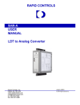
Program Switch
The Program Switch is used to enable or disable programming of the 7700 Module. The
module is programmable (Program Mode, PRG light ON) when the switch is pushed towards the
back of the module. When in Program Mode, all parameters can be modified. The module is not
programmable (Display Mode, PRG light OFF) when the switch is pushed towards the front of the
module. When in Display Mode, the Count Direction, FS Length, FS Count, and Position Offset
can be examined but cannot be modified.
Remove system power before
removing or installing a module in
the I/O Rack. Failure to observe this warning can result in
damage to the module's circuitry and/or undesired operation
with possible injury to personnel.
! W A R N IN G
The Program Switch can be disabled by removing the
jumper on the two pin header next to the switch. Removing
this jumper locks the 7700 in Display Mode. It is usually
good practice to remove this jumper once the system is
operational. This will prevent someone from accidentally
changing the 7700's parameters while the system is running.
The only times that changes to the modules programming
should be allowed are during set-up or trouble shooting
procedures.
Two Pin Header shown with Jumper installed.
Program Switch shown in Program Mode position.
Fig 2.23 Program Switch
ADVANCED MICRO CONTROLS INC.
2-9
Chapter 2 Series 7700 Module Description
Keyboard Description
The following table describes what the keys do when you are in Display Mode, (PRG light OFF)
or Program Mode (PRG light ON). When in Program Mode, a parameter that you show on the
display can be changed if one of the digits on the display is blinking. The blinking digit shows the
position of the Cursor.
Key
Display Mode
Program Mode
Use this key to select the
function or parameter you
wish to show on the display.
Same as Display Mode.
Not used in Display Mode.
If a parameter is shown
with the Cursor, pressing this key will store
the displayed value in
E2PROM Memory.
Use this key to recover from
fault conditions. The exact
nature of the fault is shown
on the display. See Status
Indicators Pg. 2-7.
Same as Display Mode.
If the Position Function
is on the display, press
this key to use the
AUTO PRESET feature
Used to switch between the
transducer inputs on a multichannel module.
Same as Display Mode.
Not used is Display Mode.
If the Cursor is shown,
use these keys to increment [▲] or decrement
[▼] the number under
the cursor.
Not used in Display Mode.
If the Cursor is shown,
these keys shift the Cursor to the left [Æ] or the
right [Ç] by one digit.
Fig 2.24 Keyboard Description
2-10
ADVANCED MICRO CONTROLS INC.
Chapter 2 Series 7700 Module Description
Transducer Input Connector
The Transducer Input Connector on the Series 7751 single channel Modules has eight contacts
while the Transducer Input Connector on the Series 7752 dual channel Modules has fourteen
contacts. The following table lists the AMCI and Phoenix Contact part numbers on the mating
connectors:
7751 Module
7752 Module
AMCI Part #
MS-8
MS-14
Phoenix Part
#
MSTB2.5/8-ST-5.08
MSTB2.5/14-ST-5.08
Fig 2.25 Transducer Input Connector Part Numbers
The pin-out of the cables are given in Chapter 3, Installation.
Fuse Replacement
If the Power Fuse fails, it can be easily replaced. The factory installed fuse is a 3.5 Amp Fast
Blow, Littelfuse Part Number 22503.5. Fuse kits are available from AMCI. The AMCI Part
number is SKF-1. Each fuse kit contains five fuses.
! C A U TIO N
! W A R N IN G
To insure continued and adequate protection, any replacement fuse
must have a rating of 3.5 Amp Fast Blow. Using a higher ampere
rating or slow blow fuses may not protect the module from
damage if the fault conditions are again applied to the module.
Remove system power before removing or installing a module in
the I/O Rack. Failure to observe this warning can result in damage
to the module's circuitry and/or undesired operation with possible
injury to personal.
Po we r F use
Fig. 2.26 Power Fuse
ADVANCED MICRO CONTROLS INC.
2-11
Chapter 2 Series 7700 Module Description
Specifications
Module Location
Velocity Data Response Time
Any 1771 I/O chassis, occupies two slots
Programmable to 32, 60, 120, or 240
mSec
Position Transducer
AMCI LHT Series LDTs.
Balluff LDT with ‘K2’ output option.
MTS Temposonics™ II LDT with RPM or
DPM Personality Modules.
Determined by, and identical to, the
Position Resolution.
Velocity Data Range
Transducer Input
0 to 99999 Counts/sec
Optically Isolated (1500 Vac)
Data Transfer
Number of Recirculations
Programmable for BTR or Single
Transfers
1: Resolution ≤ 0.01"
2: Resolution > 0.01 and < 0.002"
4: Resolution ≥ 0.002 and ≤ 0.001"
Data Available to Processor
Programmable Parameters
Magnet Position, Magnet Velocity, and
Fault Diagnostics
Count Direction
Full Scale Length
Full Scale Count
Position Offset
Connection Type
DPM Recirculations
Measurement Unit
LDT Gradient
Decimal Point Position
Preset Value
Speed Average
Data Format
Transfer Type
Program Input
Modules' self-contained display and
keyboard or BTW from Processor.
Program Storage
E2PROM Memory
DC Supply Voltage from Backplane
+5 Volts @ 1.45A max. (7752 Module)
Module +5Vdc Supply Fuse
Measurement System
Programmable to inches or millimeters
2A Fast Blow (Littelfuse 225002)
Environmental Conditions
Position Resolution
To 0.001 inches:
LDT Length
99 "
To 0.010 inches:
LDT Length
650 "
Position Offset
Programmable to any point on LDT's
length.
Used to set the reference point on the
LDT.
2-12
Velocity Data Resolution
Operating Temperature: 0 to 60° C
Relative Humidity
w/o condensation:
5 to 95%
Storage Temperature:
-40 to 85°
Connector Keying
Between 28 and 30
Between 34 and 36
ADVANCED MICRO CONTROLS INC.
Chapter 3 Installation
Power Requirements
A Series 7700 Module draws it's power from the I/O Chassis backplane +5 Vdc Supply. The
maximum current draw by a 7700 Module is 1.45 Amps. Add this to the power requirements of all
other cards in the chassis to avoid exceeding backplane or supply capacity.
Installing the Module
! W A R N IN G
Remove system power before removing or installing a module in the I/O
Chassis. Failure to observe this warning can result in damage to the
module's circuitry and/or undesired operation with possible injury to
personal.
When the module is installed, it should be placed in a single slot pair within the chassis. Doing
this will help you avoid addressing conflicts between the 7700 Module and a 16 bit I/O Card when
using 2-Slot addressing or a 32 bit I/O Card when using 1-Slot addressing. A slot pair is made up
of the two slots under each module locking latch. Figure 3.1 shows two 7700 Modules. The
module on the left is correctly installed in a single slot pair while the module on the right is
incorrectly installed in two slot pairs.
Fig 3.1 Module Installation
Keying Bands
Plastic keying bands can be inserted into the slot that the 7700 Module plugs into to insure that
a different module cannot be inserted into the slot accidentally. The keying bands must be inserted
in the top backplane connector to allow insertion of a 7700 Module:
− Between 28 and 30
− Between 34 and 36
ADVANCED MICRO CONTROLS INC.
3-1
Chapter 3 Installation
Compatible Transducers
Presently, the Series 7700 Modules have been tested with AMCI’s LHT Series LDTs, Balluff
LDTs with a ‘K2’ Output/Power Supply Option, and MTS’s Temposonics II LDTs. The modules
will interface with a Temposonics II as long as it has an RPM or DPM Personality Module
installed in its head.
Temposonics II DPM Setup
Located on the DPM Personality Module are switches that are used to configure it for various
resolutions and internal or external interrogation. You should refer to MTS documentation for
specifics on configuring the module. The 7700 Series require that the DPM be configured for
External Interrogations and four recirculations. Switches 1 and 2 on the DPM are used to set the
Intergation source and the number of recirculations. Switch 1 (SW1) must be set to position 4,
Switch 2 (SW2) must be set to position 8.
Transducer Mounting
Refer to the documentation you recieved with your LDT to properly mount the transducer.
Grounding Clamp
The shield of the Transducer Cable must be attached to the chassis with a Grounding Clamp
(AMCI part number GC-1) in order to provide a low impedance path to ground for any EMI
radiation that may be induced into the cable. The drain wire from the Grounding Clamp must be
connected to pin 4 of the MS-8 or MS-14 Transducer Input Connector. Pin 13 of the MS-14
connector is internally connected to pin 4 and does not need an additional wire.
G R O U N D IN G C L A M P
Fig 3.2 GC-1 Grounding Clamp Installation
3-2
ADVANCED MICRO CONTROLS INC.
Chapter 3 Installation
Cable Installation
Cables can be ordered directly from the LDT manufacturer. Optionally, MTS specifies
BELDEN #8105 for use as an extension cable.
Cable Prints are at the back of this manual. The following table lists print numbers and page
numbers to refer to based on module and transducers types.
7751
7752
AMCI/ Balluff
B1241 (P-3)
B1242 (P-4)
Temposonics II
B1178 (P-4)
B1177 (P-5)
ADVANCED MICRO CONTROLS INC.
3-3
Chapter 3 Installation
Notes:
3-4
ADVANCED MICRO CONTROLS INC.
Chapter 4 Keyboard Programming
This chapter offers examples on how to program the Series 7700 modules. Unless noted, all
programming examples are applicable to all Series 7700 Modules.
Before any of the Series 7700's parameters can be programmed, the module must be in Program
Mode. (Program Switch set ON. See Program Switch Pg. 2-9 for more information.) When the
module is in this mode, the yellow PRG light on the front panel is lit.
Conventions
The following conventions are used when describing the keystrokes needed to program the
different parameters.
[KEY]:
Used to show the key pressed on the module. The key's name will be inside the
brackets.
If an asterisk appears before a key, (Example: *[FUNCTION]), the key must be
pressed until the display matches what is shown in the instructions.
If a "X" and a number follow a key, (Example: [▲]X3), the key must be pressed the
shown number of times. (In this example, the [▲] key would be pressed 3 times.)
IND. LEDS: Indicator LEDs that indicate the function or parameter being displayed or
programmed.
"Display": Information shown on the 6 digit display. The blinking cursor is shown by a
double underline.
The following keystroke examples use the least number of keystrokes. However, any series of
keystrokes is valid as long as the data is correct before the [ENTER] key is pressed.
Scaling Parameters
Count Direction
You are using the Temposonics LDT to measure the liquid level in a 250 gallon cylindrical
tank to 0.01 gallons. The transducer is mounted above the tank so you need the position values to
decrease as the magnet moves away from the LDT head. You can accomplish this by changing the
Count Direction Parameter to "negative".
If the Count Direction Parameter is Positive, the value of the Position Function is the Position
Offset plus the True Position. If the Count Direction Parameter is Negative, the value of the
Position Function is the Position Offset minus the True Position. The True Position is the actual
distance from the magnet to the pickup coil in the head of the LDT.
PRESS
IND. LEDS
DISPLAY
COMMENTS
A
" dir P"
Present Value.
[▲]
A
" dir n"
Parameter changed to
negative count direction.
[ENTER]
A
" dir n"
Value stored in E²PROM.
Blinking cursor removed.
*[FUNCTION]
ADVANCED MICRO CONTROLS INC.
4-1
Chapter 4 Keyboard Programming
Scaling Parameters (cont'd)
Full Scale Length
The LDT length is 72 inches but only 40 inches of the probes' length will be used. Instead of
entering the length of the LDT you can enter the distance that the LDTs' magnet will travel. In this
case, it simplifies the calculations needed to determine the Full Scale Count.
PRESS
IND. LEDS
DISPLAY
COMMENTS
*[FUNCTION]
A
"L 0016"
Default Value.
[Ç]X2, [▲]X3, [Ç],
[▲]X4, [ENTER]
A
"L 0040"
Value stored in E2PROM.
Blinking Cursor removed.
Full Scale Count
In most applications, the Full Scale Count is simply the Full Scale Length multiplied by a
power of ten. This gives a position value that reads out directly in the desired unit of length. This
is not the case for the example in Application Notes where the Position Function reads out in
hundredths of gallons. 250 Gallons multiplied by 100 Counts per Gallon equals 25000 Counts.
PRESS
IND. LEDS
DISPLAY
COMMENTS
*[FUNCTION]
SF + A
" 40000"
Default for 40" Length.
[▼]X2, [Ç], [▲]X5,
[ENTER]
SF + A
" 25000"
Value stored in E2PROM.
Blinking Cursor removed.
Position Offset
The Position Offset is used to change the value of the Position Function without moving the
LDTs' magnet.
There is a True Position that the 7700 reads from the LDT. This position is the distance
between the magnet and the pickup coils in the LDTs' head. Due to the manufacturing process, the
True Position can vary from probe to probe by a small amount. The value of the Position Function
is equal to the Position Offset added to the True Position. Note that the signs of the Position
Offset and True Position are significant.
In most cases, you can use the Auto Preset feature to set the value of the Position Function
instead of calculating the Position Offset. Using the Auto Preset, the Position Offset will be
automatically calculated by the 7700. It is then simple, if necessary, to vary the Position Offset by
small amounts from the Position Offset display.
4-2
ADVANCED MICRO CONTROLS INC.
Chapter 4 Keyboard Programming
Scaling Parameters (cont'd)
Position Offset (cont'd)
In this example, the Position Offset equals 32080 and must be changed to -32069.
PRESS
IND. LEDS
DISPLAY
COMMENTS
*[FUNCTION]
O+A
" 32080"
Present Value.
[Æ], [▲], [Ç]X4,
[▼]X2, [Ç], [▼],
[ENTER]
O+A
"-32069"
Value stored in E2PROM.
Blinking Cursor removed.
Setup Parameters
The rest of the programmable parameters on the 7700 are Setup Parameters. They are available
only when you are in Program Mode. The following keystrokes show you how to access these
parameters.
PRESS
*[FUNCTION]
[ENTER]
IND. LEDS
DISPLAY
COMMENTS
None
" SEtUP"
Setup Menu Display.
A
"Con rP"
First Setup Parameter. Other
values available by pressing
the [FUNCTION] Key.
LDT Type
You are using a Temposonics II LDT that contains a DPM Personality Module. Presently, the
7700 is in its default configuration for AMCI LDT’s.
PRESS
IND. LEDS
DISPLAY
COMMENTS
*[FUNCTION]
A
" Ldt 1"
Default Value, AMCI LDT’s.
[▲] X2, [ENTER]
A
" Ldt 3"
Value stored in E2PROM.
Blinking Cursor removed.
ADVANCED MICRO CONTROLS INC.
4-3
Chapter 4 Keyboard Programming
Setup Parameters (cont'd)
DPM Recirculations
If a DPM Personality Module is used, the number of recirculations that it is set for must also be
programmed into the 7700. Possible numbers are 1, 2, and 4 recycles. The LDT can be set for a
higher number of recirculations without effecting the resolution, but the position update time will
be longer. The minimum number of recirculations needed for a desired resolution is listed in
Specifications, Pg 2-12.
It is imperative that the number of recirculations set on the DPM module and DPM
Recirculations Parameter be equal. If they are not, the 7700 will not calculate correct
position or velocity data.
To decrease position update time and simplify your ladder logic program, you decide to limit
your position values from 20 bits to 12 bits. Decreasing the resolution of the system allows you to
change the number of recirculations from four to two. Note that the number of recirculations that
the DPM Personality Module is set for must also be changed.
PRESS
IND. LEDS
DISPLAY
COMMENTS
*[FUNCTION]
A
" rC 4"
Present Value.
[▼], [ENTER]
A
" rC 2"
Value stored in E2PROM.
Blinking Cursor removed.
Measurement Unit
You are using a LDT that has its length and Gradient specified in millimeters. In order to simplify programming, you can change the Measurement Unit from the default of inches to
millimeters.
Changing this parameter will reset all other parameters to their default values except
the Connection Type and Speed Average parameters.
PRESS
4-4
IND. LEDS
DISPLAY
COMMENTS
*[FUNCTION]
A
"Unit i"
Present Value.
[▼], [ENTER]
A
"Unit d"
Value stored in E2PROM.
Blinking Cursor removed.
ADVANCED MICRO CONTROLS INC.
Chapter 4 Keyboard Programming
Setup Parameters (cont'd)
LDT Gradient
The LDT Gradient is the velocity at which the return pulse propagates down the length of the
transducer shaft. The value of the LDT Gradient varies from transducer to transducer. It's value is
printed on the label of the LDT.
In this example, the LDT Gradient printed on the labelof a Temposonics II is 8.9986 µSec per
Inch. Presently, the default value of 9.03000 is stored in memory.
PRESS
*[FUNCTION]
[▼], [Ç], [▼],
[Ç], [▼]X4, [Ç],
[▼]X2, [Ç], [▼]X4,
[ENTER]
IND. LEDS
DISPLAY
COMMENTS
SF + A
" 9.03000"
Default Value.
" 8.99860"
Value stored in E2PROM.
Blinking Cursor removed.
SF + A
Decimal Point Position
You want to program a Decimal Point so that the last two digits on the position display are after
it. The parameter presently has it's default setting of 0.
PRESS
*[FUNCTION]
[▲]X2, [ENTER]
IND. LEDS
DISPLAY
COMMENTS
A
" d.P. 0"
Default Value.
A
" d.P. 2"
Value stored in E2PROM.
Blinking Cursor removed.
Preset Value
You want to program a Preset Value of 25000 Counts. Presently, the default value of zero is in
memory.
PRESS
IND. LEDS
DISPLAY
COMMENTS
*[FUNCTION]
SF + O + A
" 00000"
Default Value.
[▲]X2, [Ç], [▼]X5,
[ENTER]
SF + O + A
" 25000"
Value stored in E2PROM.
Blinking Cursor removed.
ADVANCED MICRO CONTROLS INC.
4-5
Chapter 4 Keyboard Programming
Setup Parameters (cont'd)
Speed Average
You wish to change the Speed Average from it's default setting of 120 mSec to 240 mSec. The
Speed Average parameter sets the amount of time that the 7700 Module totals the change in
position of the magnet before calculating it's velocity in Counts per Second. Increasing the Speed
Average will reduce the amount of "jitter" that may occur in the velocity data.
PRESS
*[FUNCTION]
[▲], [ENTER]
IND. LEDS
DISPLAY
COMMENTS
A
"S.A. 120"
Default Value.
A
"S.A. 240"
Value stored in E2PROM.
Blinking Cursor removed.
Data Format
You are using a PLC-2/16 processor in your application. Because all of the PLC-2's math
instructions use BCD numbers, you want the Position and Velocity data in BCD format.
PRESS
*[FUNCTION]
[▲], [ENTER]
IND. LEDS
DISPLAY
COMMENTS
NONE
" bin "
Default Value.
NONE
" bcd "
Value stored in E2PROM.
Blinking Cursor removed.
Transfer Type
You are using a PLC-2/20 processor in your application. Because this processor does not have
Block Transfer Instructions, you must configure the module to use Single Transfers.
PRESS
*[FUNCTION]
[▲], [ENTER]
4-6
IND. LEDS
DISPLAY
COMMENTS
NONE
" blc "
Default Value.
NONE
" Sin "
Value stored in E2PROM.
Blinking Cursor removed.
ADVANCED MICRO CONTROLS INC.
Chapter 4 Keyboard Programming
Auto Preset Feature
The Position Function can be forced to equal the Preset Value Parameter without the need to
calculate the Position Offset. This allows you to quickly set a reference position on the LDT. In
the example in Applications Notes this reference point is 250.00 and corresponds to the
cylindrical tank being full.
In order to use the Auto Preset Feature, you must have the 7700 in Program Mode and the
Position data must be showing on the display.
PRESS
*[FUNCTION]
[CLEAR]
*[FUNCTION]
IND. LEDS
DISPLAY
COMMENTS
POS + A
" xxx.xx"
Present Position Value.
POS + A
" 250.00"
Position = Preset Value.
O+A
"yyyy.yy"
Calculated Position Offset.
ADVANCED MICRO CONTROLS INC.
4-7
Chapter 4 Keyboard Programming
Notes
4-8
ADVANCED MICRO CONTROLS INC.
Chapter 5 AMCI Module Addressing
Module Addressing
This chapter explains how to address a Block Transfer module and is applicable to all AMCI
products for the 1771 I/O structure. Also covered is addressing a Single Transfer module, which is
applicable to the 1731, 1741 and 7751 Modules. When information in this chapter applies to an
"AMCI Module", it applies to all Series 1700, 2700, and 7700 Modules. When information only
applies to specific modules, product numbers of the effected modules are listed.
When you configure your Programmable Controller System, you specify a unique address for
each slot of each chassis in the system. An I/O Rack number and an I/O Group Number make up
each address. An I/O Slot number further specifies a Block Transfer address.
Note that an I/O Chassis is not the same as an I/O Rack Number. An I/O Chassis is the
physical enclosure that the cards and modules plug into. An I/O Rack Number is part of
a modules' address in the system. Each I/O Chassis can have ¼ to 4 I/O Racks associated
with it.
Definition of Terms
I/O Rack
The number of I/O Racks in the system, not the number of chassis, define the Programmable
Controller System. In PLC-2 systems, the first I/O Rack is assigned the number 1. In PLC-3 or
PLC-5 systems, the first I/O Rack is assigned the number 0. Each I/O Rack is further divided into
8 I/O Groups.
I/O Group
Eight I/O Groups make up 1 I/O Rack. The eight I/O Groups of each I/O Rack are assigned the
numbers 0 through 7. Each slot in a chassis is assigned ½, 1, or 2 I/O Groups. You do this when
you select which Slot Addressing to use in the chassis.
Slot Addressing
There are 3 different slot addressing schemes used by Allen-Bradley. They are 2 Slot, 1 Slot,
and ½ Slot Addressing.
I/O G roup
N u m ber
I/O R ack N um ber 0
0
0
1
1
0
2
1
3
4
0 1 0 1 0 1 0
Module S lot N um bers
5
6
1
0
With 2-Slot Addressing, 1 I/O Group is
assigned to a slot pair in the chassis. A
slot pair is made up of the two slots under
a single module locking latch. The first
slot of the pair is given the Module Slot
Number 0. The second slot of the pair is
given the Module Slot Number 1.
7
1
0
1
Fig 5.1 2-Slot Addressing
ADVANCED MICRO CONTROLS INC.
5-1
Chapter 5 AMCI Module Addressing
Module Addressing (cont'd)
Slot Addressing (cont'd)
I/O G roup
N u m ber
I/O R ack N um ber 0
0 1
2 3
0
0
0
0
4 5
6 7
I/O R ack N um ber 1
0 1
2 3
0 0 0 0 0 0 0
Module S lot N um bers
0
4 5
6 7
0
0
0
With 1 Slot Addressing, 1 I/O Group is
assigned to each slot in the chassis. Each
slot is given the Module Slot Number 0.
0
Fig 5.2 1-Slot Addressing
I/O G roup
N u m ber
I/O R ack 0
0,1 2,3
0
0
I/O R ack 1
4,5 6,7 0,1 2,3
0
0
I/O R ack 2
4,5 6,7 0,1 2,3
I/O R a ck 3
4,5 6,7 0,1 2,3
0 0 0 0 0 0 0
Module S lot N um bers
0
0
0
4,5 6,7
0
With ½ Slot Addressing, two I/O
Groups are assigned to each slot. Each
slot is given the Module Slot Number 0.
0
Fig 5.3 ½-Slot Addressing
Addressing a Block Transfer Module
All AMCI Modules communicate with the PLC through Block Transfers. The PLC can read
data from the AMCI Module with Block Transfer Read (BTR) Instructions and program the
Modules' Programmable Parameters with Block Transfer Write (BTW) Instructions.
A BT module's address is made up of three numbers. They are the I/O Rack Number, the I/O
Group Number, and the Module Slot Number.
M O DULE A DDRE SS = R G S
I/O Rack N um b er
I/O G roup Num ber
M odule Slo t Num ber
Fig 5.4 BT Module Address
5-2
ADVANCED MICRO CONTROLS INC.
Chapter 5 AMCI Module Addressing
Addressing a Single Transfer Module
The single channel Transducer Interface Modules, the 1731/41 and the 7751, can transfer
position data to the PLC with Single Transfers. The transfer is done automatically at the
beginning of every scan between the Input Image Table and the Interface Module. To access the
Position data from a 1731/41 or 7751 Module that uses Single Transfers, you must know the
memory location in the Input Image Table associated with the module.
− PLC-2: Three or four digit number. The first is a "1", followed by the I/O Rack and I/O
Group
Numbers.
− PLC-3: The letter "I" followed by a four digit number. The first three digits are I/O Rack
Number, followed by I/O Group Number.
− PLC-5: The characters "I:" followed by a two or three digit number. The first one or two
digits
are the I/O Rack Number, followed by the I/O Group Number.
When specifying an address in the Input Image Table, all I/O Rack numbers are
expressed in octal. (i.e. 00, 01, 02, ... 06, 07, 10, 11, ......)
Addressing Examples
The following three figures show how to address an AMCI Module when using 2-Slot, 1-Slot,
and ½-Slot Addressing. The addresses used when the module is configured for Block or Single
Transfers are shown. Note the following:
− Only the 1731/41 or the 7751 Modules can use Single Transfers.
− You cannot use Single Transfers if your I/O Chassis is set-up for 2-Slot Addressing. This
restriction is imposed by the Allen-Bradley TIC chip.
− When using ½-Slot addressing the I/O Group Number used in the address is the lower of the
two I/O Group Numbers assigned to the slot.
In all of the following figures, the module is placed in a single slot pair. (Under a single
locking latch, see Installing the Module Pg 3-1 for more information.) If the practice of installing
an AMCI Module in a single slot pair is followed, the Addressing Shortcuts listed next to the
figures can be used.
I/O G roup
N u m ber
I/O R ack N um ber 0
Module BT Address = 041
0
1
2
3
4
5
6
7
Single Transfer cannot be used by the
1731/41 or 7751 Modules.
Addressing Shortcuts
1) Slot Number is always equal to 1.
0
1
0
1
0 1 0 1 0 1 0
Module S lot N um bers
1
0
1
0
1
Fig 5.5 Modules' 2-Slot Address
ADVANCED MICRO CONTROLS INC.
5-3
Chapter 5 AMCI Module Addressing
Addressing Examples (cont'd)
I/O G ro u p
N um ber
I/O R ack N um ber 0
0 1
2 3
4 5
6 7
I/O R ack N um be r 1
0 1
2 3
4 5
6 7
Module BT Address = 110
PLC-2 Single Addr = 111
PLC-3 Single Addr = I0011
PLC-5 Single Addr = I:011
Addressing Shortcuts
1) I/O Group Number is always odd
2) Slot Number is always equal to 0.
0
0
0
0
0 0 0 0 0 0 0
M odule S lot N um bers
0
0
0
0
0
Fig 5.6 Modules' 1-Slot Address
I/O G ro u p
N um ber
I/O R a c k 0
0,1 2,3
I/O R a ck 1
4 ,5 6,7
0,1 2,3
4,5 6,7
I/O R a ck 2
0,1 2 ,3
I/O R a ck 3
4,5 6,7
0 ,1 2 ,3
4,5 6,7
Module BT Address = 220
PLC-2 Single Addr = 122
PLC-3 Single Addr = I0022
PLC-5 Single Addr = I:022
Addressing Shortcuts
1) I/O Group Number is always even.
2) Slot Number is always equal to 0.
0
0
0
0
0 0 0 0 0 0 0
M odule S lot N um bers
0
0
0
0
0
Fig 5.7 Modules' ½-Slot Address
General Restrictions and Warnings
1. It is important to have the AMCI Module installed in a single slot pair. See Installing the
Module Pg 3-1. Doing this will avoid any potential addressing conflicts when using a 1700
Module and 16 pt. modules with 2-Slot addressing or 32 pt. modules with 1-Slot addressing.
2. When using an AMCI Module as a Block Transfer Module in a chassis that uses a Remote I/O
Adapter, the I/O Adapter must be a 1771 - ASB, Series B, Firmware Rev. F, or later. Using a
Remote I/O Adapter that has an earlier Series or Firmware Revision may not work properly
with a BT Module.
5-4
ADVANCED MICRO CONTROLS INC.
Chapter 5 AMCI Module Addressing
Single Transfer Restrictions and Warnings
1. When using a 1731/41 or 7751 as a Single Transfer Module, the chassis that contains the
module CANNOT be set-up for 2-Slot addressing. This is because of restrictions imposed by
the Allen-Bradley TIC chip.
2. If you change the Transfer Type Parameter on a 1731/41 or 7751, you MUST cycle power to
the chassis that contains the module to re-initialize the A-B TIC chip.
3. If you have a system that presently uses a 1731/41 or 7751 as a BT Module and you are changing the system to use it as a Single Transfer Module, you must remove all BT Instructions
from your program that address the Module. BT Instructions write information in the Input
and Output Data Tables that may corrupt the data being transferred by the module.
4. The 1700 modules and A-B PLCs read data from the TIC chip one byte at a time. Therefore, it
takes two memory read or write cycles to transfer one 16 bit word of data. In order to prevent
data corruption*, the TIC chip is setup to interrupt the module when the PLC has read a
complete word of data. The module accepts this interrupt immediately and write the latest
position data to the TIC chip. The module then waits for the next interrupt before again
writing to the TIC chip. Because of this, the position data available to the processor is 1 scan
time behind the actual transducer position. In most applications this does not cause a
significant error but if your application involves high transducer speeds or long scan times this
delay can be avoided by placing two back to back Immediate Input Instructions in your ladder
logic.
*
Data Corruption occurs when:
1) The PLC reads one byte of "old" position data.
2) The module updates the position data
3) The PLC reads one byte of the "new" position data.
For example, if the old position data is 07FFh and the new position data is 0006h the PLC will
read 0706h as the position data.
ADVANCED MICRO CONTROLS INC.
5-5
Chapter 5 AMCI Module Addressing
Notes
5-6
ADVANCED MICRO CONTROLS INC.
Chapter 6 PLC-2 Block Transfer Instructions
Overview
Most PLC-2 processors have Block Transfer Instructions in their instruction sets. There are
four parts to PLC-2 BT Instructions. They are:
− Data Address - Address in the PLC-2's Timer/Counter Accumulated Registers where the
Module Address is stored.
− Module Address - The I/O Rack, Group and Slot Numbers where the module is located.
− Block Length - Number of PLC-2 memory locations needed to store information read from
or written to the AMCI Module.
− File Address - Starting and ending addresses in PLC-2 memory where the data is stored.
Data and Module Address
The value of the Data Address is the memory location that stores the Module Address. Each
BT Instruction needs a different Data Address, even if you have multiple BT Instructions for one
module (i.e., the Module Addresses are the same). The value of the Data Address must be the first
available memory location in the Timer/Counter Accumulated Registers and all Data Addresses
MUST come before ANY Timer or Counter Accumulated Registers.
The number of I/O Racks in your system determines the first memory location of the T/C
Accumulated Registers section in PLC-2 Data Table. Figure 6.1 shows the first available memory
location based on the number of I/O Racks that the processor is configured for.
Number of I/O Racks
1
2
3
4
5
6
7
First Available Address
020
030
040
050
060
070
200
Fig 6.1 First Memory Location of T/C Accumulated Register Memory
After all BT Data Addresses have been assigned, the next memory location should be
loaded with the value 0000. This prevents the PLC-2 from using a timer or counter value
as the address of a BT Module by forming a boundary that the PLC-2 will not cross when
searching for a Module Address.
Block Length
The Block Length is the number of words needed to store the information read from or written
to the AMCI Module. When programming a BTR Instruction, you can set the Block Length to 00.
This will reserve 64 words in the PLC-2 memory, but the module will only transmit the number of
words necessary. When programming a BTW Instruction, the number of words needed depends
on the number of Program Instructions that you are writing to the AMCI Module.
The Block Length of a BTW Instruction MUST equal the number of words used by the
Program Instructions. Using a Block Length of zero will cause an Invalid Command
Error if the number of words used by the Program Instructions is not 64.
ADVANCED MICRO CONTROLS INC.
6-1
Chapter 6 PLC-2 Block Transfer Instructions
Block Length (cont'd)
The following tables list the number of words transmitted to the PLC when a BTR Instruction
is executed. Chapter 9 Data Format, gives the format of the transmitted data.
1700 USERS: To make the present 1700 modules compatible with older versions,
you must set the Module to Read Only with the PLC Program Parameter. If you set
the PLC Program Parameter to Read Only, the number of words transmitted by the
1700 Module is the second number listed in the following table.
1700 Module
1731/41
1732/42
1733/43
1734/44
1761
1762
1763
Block Length
3/2
5/4
7/6
9/8
4/3
7/6
5/4
Fig 6.2 1700 Module Block Length
2700 Module
2731/41
2732
7700 Module
7751
7752
Block Length
3
5
Block Length
5
9
Fig 6.3 2700 Module Block Length
Fig 6.4 7700 Module Block Length
File Address
The File Address is the first address in PLC-2 memory where you want to store data that is read
from or written to the AMCI Module. The PLC programming software calculates the ending
address based on the Block Length. The PLC-2 stores the value of the File Address at 1008
memory locations above the value of the Data Address in the Timer/Counter Preset Value section
of the Data Table. There are two areas in the PLC-2 memory that you can use to store the Block
Transfer File.
The first, and preferred area, is in an expansion area. You can set this area aside when you setup the system. Each expansion area is 128 words long and is the last section of the Data Table
before the User Program. The expansion area has the advantage of being completely under your
control because it is not used for any of the processor's functions.
The second area that you can use to store the Block Transfer File is in any unused memory in
the T/C Accumulated or T/C Preset Values sections. These areas have the advantage of using
memory that would otherwise be wasted, but have the disadvantage of potentially being
overwritten by a Timer or Counter Instruction.
Enable (EN) and Done (DN) Bits
Used to signal the start and finish of a Block Transfer, the processor sets the EN bit to start the
transfer and after successfully completing the transfer the module sets the DN bit. You should use
the DN bit to buffer the data coming from the module. This prevents the program from using
invalid Position and Velocity data from the AMCI Module.
The EN bit is located in the Output Image Table. The DN bit is located in the Input Image
Table. Both BTR EN and DN bits are at bit number 078 if the module is in slot 0 or at 178 if the
module is in slot 1. The BTW EN and DN bits are located at bit number 068 or 168.
6-2
ADVANCED MICRO CONTROLS INC.
Chapter 6 PLC-2 Block Transfer Instructions
Programming Example
The following example assumes 1-Slot addressing and an AMCI Module in the first slot group
of the processor rack.
Rung 1: BTR Instruction to the AMCI Module. The Block Transfer Read executes every scan
except when a Block Transfer Write is requested. The BTR must be disabled because
the BTR and BTW files are of different lengths.
Rung 2: When the Block Transfer Read is completed, the BTR Done bit is set. This energizes
the File to File Move that buffers data from the AMCI Module. The program uses the
data at addresses 205 - 209 in the rest of the program.
Rung 3: The Block Transfer Write is requested whenever CR1 is latched on.
Rung 4: CR1 is latched on when a BTW Request is made.
Rung 5: CR1 is unlatched when the BTW Request is removed and the BTW Done bit is set.
BLO CK XFER READ
DATA ADDR:
030
M ODULE ADDR: 110
B LO C K LE N G T H : 0 5
F IL E :
2 00 - 2 04
CR 1
BTR
F ILE T O F ILE M O V E
CO UNTER ADDR: 033
P O S IT IO N :
110
F IL E L E N G T H :
05
F IL E A :
2 00 - 20 4
F IL E R :
20 5 - 2 09
RATE PER SCAN: 005
DN
B L O C K X F E R W R IT E
DATA ADDR:
031
M ODULE ADDR: 110
B LO C K LE N G T H : 2 3
F IL E :
3 00 - 3 22
CR 1
BTW Request
011
( EN )
07
111
( DN )
07
033
( EN )
17
033
( DN )
15
011
( EN )
06
111
( DN )
06
CR 1
(L)
BTW Request
BTW
CR 1
(U )
DN
Fig 6.5 PLC-2 Programming Example
ADVANCED MICRO CONTROLS INC.
6-3
Chapter 6 PLC-2 Block Transfer Instructions
PLC-2 Restrictions and Warnings
! W A R N IN G
The following restrictions must be followed when using a BT
Module in a PLC-2 System. If these restrictions are not followed,
unpredictable operation may occur.
1. It is important to have an AMCI Module installed in a single slot pair. (See Installing the
Module Chapter 3.) Doing this will avoid any potential addressing conflicts when using an
AMCI Module and 16 pt. modules with 2-Slot addressing or 32 pt. modules with 1-Slot
addressing.
2. When using an AMCI Module as a Block Transfer Module in a chassis that uses a Remote
I/O Adapter, the I/O Adapter must be a 1771 - ASB, Series B, Firmware Rev. F, or later.
Using a Remote I/O Adapter that has an earlier Series or Firmware Revision may not work
properly with a BT Module.
3. When using a single channel Transducer Interface Module, (1731/41, 7751), as a Single
Transfer Module, the chassis that contains the module MUST be set-up for 1-slot or ½-slot
addressing. 2-Slot addressing will not function properly. This is because of the restrictions
imposed by the Allen-Bradley TIC chip.
4. If remote racks are being used, words 1258 and 1268 are used to store remote I/O fault bits.
BT and Input Modules must not be placed in the following slots: RACK 2, Groups 5 and 6.
5. Word 027 in the Output Image Table is reserved for processor use. DO NOT put a BT
Module in I/O Rack 2, I/O Group 7.
6. The starting File address cannot exceed address 177778.
7. The maximum number of Block Transfers that can be handled by Rev J firmware of the
PLC-2/30 processor module is fifty.
8. Each BT Module decreases the total number of available Timer or Counters by 1. The File
to File Move Instruction used to buffer the data from an AMCI module also requires 1
Counter. If you need the counter, you can replace the File to File Move Instruction with a
series of GET - PUT Instructions that are conditioned with the BTW Done bit.
6-4
ADVANCED MICRO CONTROLS INC.
Chapter 7 PLC-3 Block Transfer Instructions
Overview
All PLC-3 processors have Block Transfer Instructions in their instruction sets. There are four
parts to PLC-3 BT Instructions. They are:
− Module Address - The I/O Rack, Group, and Slot Numbers where the module is located.
− Data Address - The starting file address that stores data written to or read from the module.
− File Length - The number of words needed to store data written to or read from the module.
− Control File - The starting address of the file used to control the Block Transfer.
Module Address
The Module address is the I/O Rack, Group, and Slot Numbers where the module is located in
the system. The I/O Rack, Group, and Slot Numbers are entered separately in the Block Transfer
Instruction.
Data Address
The Data File is the block of words that stores the information read from or written to the
AMCI Module. The Data Address is the first address of the file. The Data File must have an
Integer of Binary data type and can be a separate file or part of a larger file. Note that you must
create the Data File before the program is executed. You create the file from your program loader.
For details on creating files, refer to the users manual for your program loader.
File Length
The File Length is the number of words in your data file. When programming a BTR
Instruction, you can set the Block Length to 00. This will reserve 64 words in the PLC-3 memory,
but the module will only transmit the number of words necessary. When programming a BTW
Instruction, the number of words needed depends on the number of Program Instructions that you
are writing to the AMCI Module.
The File Length of a BTW Instruction MUST equal the number of words used by the
Program Instructions. Using a File Length of zero will cause an Invalid Command Error
if the number of words used by the Program Instructions is not 64.
The table below lists the number of words transmitted by a 1700 Module when a BTR
Instruction is executed. Chapter 9 Data Format, gives the format of the transmitted data.
1700 USERS: To make the present 1700 modules compatible with older versions, you
must set the Module to Read Only with the PLC Program Parameter. If you set the
PLC Program Parameter to Read Only, the number of words transmitted by the 1700
Module is the second number listed in the following table.
1700 Module
1731/41
1732/42
1733/43
1734/44
1761
1762
1763
Block Length
3/2
5/4
7/6
9/8
4/3
7/6
5/4
Fig 7.1 1700 Module Block Length
ADVANCED MICRO CONTROLS INC.
7-1
Chapter 7 PLC-3 Block Transfer Instructions
File Length (cont'd)
The tables below list the number of words transmitted by a 2700 or 7700 module when a BTR
Instruction is executed. Chapter 9 Data Format gives the format of the transmitted data.
2700 Module
2731/41
2732
Block Length
3
5
7700 Module
Block Length
Fig 7.2 2700 Module Block Length
7751
7752
5
9
Fig 7.3 7700 Module Block Length
Control File
The Control File is the 10 word long file that controls the actual transfer of data. The address
that you enter into the BT Instruction if the first address of the file. The Control File MUST have
a Binary data type. Each AMCI Module requires its own Control File. The Control File can be
used to control both BT Reads and BT Writes to the module. Unlike Data Files, a Control File is
automatically made by the program loader when you enter the address of the Control File. The
Control File contains all of the information entered by the Instruction along with the Control Bits.
Latch Enable (LE), Error (ER), and Done (DN) Bits
Used to signal the start and finish of a Block Transfer, the processor sets the LE bit to start the
transfer and after successfully completing the transfer the module sets the DN bit. If an error
occurs in the transfer, the module will set the ER bit instead of the DN bit.
The LE, ER, and DN bits are located in the first word of the Control File. A Control File has
one set of bits for a BTR and a second set for a BTW. For a BT Read, the LE Bit is bit 128, the ER
Bit is bit 138 and the DN Bit is bit 158. For a BT Write, the LE Bit is bit 028, the ER Bit is bit 038
and the DN Bit is bit 058.
The LE, ER and DN bits should be used in the program to buffer the data from the module.
This is done be enabling a file to file move when the DN bit is set. This will prevent the program
from using position data from the module that may be incorrect.
There are other BT control bits in the Control File that may help you troubleshoot your system.
Refer to your PLC-3 Programming Manual for further information.
7-2
ADVANCED MICRO CONTROLS INC.
Chapter 7 PLC-3 Block Transfer Instructions
Programming Example
The following example assumes 1-Slot addressing and an AMCI Module in I/O Rack 4, I/O
Group 7 of the system.
Rung 1: BTR Instruction to the AMCI Module. The Block Transfer Read will automatically
execute every other scan because it is enabled by the DN bit.
Rung 2: When the BTR is completed, the DN bit energizes the File to File Move that buffers
data from the AMCI Module. The program uses data at addresses FN014:0005 - 9 in
the rest of the program.
Rung 3: The BT Write is enabled whenever CR1 is latched on.
Rung 4: CR1 is latched on when a BTW Request is made.
Rung 5: CR1 in unlatched when the BTW Request is removed and the BTW Done bit is set.
B T R D one
B LO C K X F E R R E A D
RACK
004
GROUP
7
M O D U LE 0 = L O W
DATA
F N 0 14:00 0 0
LENGTH 5
CNTL
F B 0 05 :00 0 0
CNTL
( LE )
12
CNTL
(D N )
15
CNTL
(E R )
13
B TR
M VF
F IL E S F R O M A T O R
DN
A : F N 01 4:00 0 0
R : F N 014 :0 0 05
C O U N T E R : C 00 1 2
P O S /LE N = 0/ 5
M O D E = A L L /S C A N
B LO C K X F E R W R IT E
RACK
004
GROUP
7
M O D U LE 0 = L O W
DATA
F N 0 15:00 0 0
L E N G T H 23
CNTL
F B 0 05 :00 0 0
CR1
C0024
(E N )
12
C0024
(D N )
15
C0024
(E R )
13
CNTL
( LE )
02
CNTL
(D N )
05
CNTL
(E R )
03
B TW R equest
CR1
(L)
B TW R equest
B TW
CR1
(U )
DN
Fig 7.4 PLC-3 Programming Example
ADVANCED MICRO CONTROLS INC.
7-3
Chapter 7 PLC-3 Block Transfer Instructions
PLC-3 Restrictions and Warnings
! W A R N IN G
The following restrictions and warnings must be followed when
using a BT Module in a PLC-3 System. If these restrictions are not
followed, unpredictable operation may occur.
1. It is important to have an AMCI Module installed in a single slot pair. (see Installing the
Module Chapter 3.) Doing this will avoid any potential addressing conflicts when using an
AMCI Module and 16 pt. modules with 2-Slot addressing or 32 pt. modules with 1-Slot
addressing.
2. When using an AMCI Module as a Block Transfer Module the Remote I/O Adapter must be a
1771 - ASB Series B, Firmware Rev. F or later. Using a Remote I/O Adapter that has an
earlier Series or Firmware may not work properly with a BT Module.
3. When using a single channel Transducer Interface Module, (1731/41, 7751), as a Single
Transfer Module, the chassis that contains the module MUST be set-up for 1-slot or ½-slot
addressing. 2-Slot addressing will not function properly. This is because of the restrictions
imposed by the Allen-Bradley TIC chip.
4. Block Transfers can take place on all four I/O Scanners simultaneously. However, if you use
the number one 1775-S4A or SR scanners, only 72 words can be transmitted on all four I/O
Channels at one time.
5. When a BT Instruction is enabled but produces an error or does not complete, the most
common problems are an incorrect Module Address or a missing Data File. You must create
the Data File from your program loader before the program can be executed.
6. Because a Block Transfer is enabled only on False to True transitions, it can be requested at
most every other scan. The programming example on page 7-3 shows how you can do this
automatically by using the EXAMINE OFF Instruction to check the status of the DN bit.
7. When the PLC-3 is powered up, it may be necessary to write a value of 0000 to the first word
of the Control Block before enabling the Block Transfer. This will clear all of the BT control
bits. This should be necessary on power up only, not every time a Block Transfer is requested.
7-4
ADVANCED MICRO CONTROLS INC.
Chapter 8 PLC-5 Block Transfer Instructions
Overview
All PLC-5 processors have Block Transfer Instructions in their instruction sets. There are five
parts to PLC-5 BT Instructions. They are:
− Module Address - The I/O Rack, Group, and Slot Numbers where the module is located.
− Control Block - The starting address of the five word block in memory that controls the
Block Transfer.
− Data File - The starting file address that stores the data written to or read from the module.
− File Length - The number of words need edto store the data written to or read from the
module.
− Continuous Parameter - Determines how often the Block Transfer is carried out.
Module Address
The Module address is the I/O Rack, Group, and Slot Numbers where the module is located in
the system. The I/O Rack, Group, and Slot Numbers are entered separately in the Block Transfer
Instruction.
Control Block
The Control Block is a block of five words that control the actual transfer of data. The address
entered into the BT Instruction is the first address of the block. The Control Block must have an
Integer data type and can be its own file or part of a larger file.
Each BT Instruction requires a separate Control Block. This is true even if a BTW and
BTR access the same module.
Data File
The Data File is the block of words that stores the information read from or written to the
AMCI Module. The Data Address is the first address of the file. The Data File must have an
Integer of Binary data type and can be a separate file or part of a larger file.
File Length
The File Length is the number of words in your data file. When programming a BTR
Instruction, you can set the Block Length to 00. This will reserve 64 words in the PLC-5 memory,
but the module will only transmit the number of words necessary. When programming a BTW
Instruction, the number of words needed depends on the number of Program Instructions that you
are writing to the AMCI Module.
The File Length of a BTW Instruction MUST equal the number of words used by the
Program Instructions. Using a File Length of zero will cause an Invalid Command Error
if the number of words used by the Program Instructions is not 64.
ADVANCED MICRO CONTROLS INC.
8-1
Chapter 8 PLC-5 Block Transfer Instructions
File Length (cont'd)
The tables below lists the number of words transmitted by a AMCI Modules when a BTR
Instruction is executed. Chapter 9 Data Format, gives the format of the transmitted data.
1700 USERS: To make the present 1700 modules compatible with older versions, you
must set the Module to Read Only with the PLC Program Parameter. If you set the
PLC Program Parameter to Read Only, the number of words transmitted by the 1700
Module is the second number listed in the following table.
1700 Module
1731/41
1732/42
1733/43
1734/44
1761
1762
1763
Block Length
3/2
5/4
7/6
9/8
4/3
7/6
5/4
Fig 8.1 1700 Module Block Length
2700 Module
2731/41
2732
Block Length
3
5
Fig 8.2 2700 Module Block Length
7700 Module
Block Length
7751
7752
5
9
Fig 8.3 7700 Module Block Length
Continuous Parameter
The Continuous parameter controls how often the Block Transfer Instruction is executed.
When the Continuous Parameter is set to "NO", the Block Transfer is executed only on a false to
true transition on the rung. This means that a non-continuous Block Transfer can occur every
other scan. When the Continuous Parameter is set to "YES", the Block Transfer will occur when
the BT Instruction is first scanned and then every scan thereafter until an error in communication
occurs.
Block Transfer Writes to an AMCI Module MUST have the Continuous Parameter set to
NO. Continuously writing Program Instructions to the module will shorten the life of the
E2PROM memory and the module will eventually give an E2PROM ERROR message.
See Status Indicators, Chapter 2 for more information.
Enable (EN), Error (ER), and Done (DN) Bits
Used to signal the start and finish of a Block Transfer, the processor sets the EN bit to start the
transfer and after successfully completing the transfer the module sets the DN bit. If an error
occurs in the transfer, the module will set the ER bit instead of the DN bit.
The EN, ER, and DN bits are located in the first word of the Control File. The EN Bit is bit 15,
the ER Bit is bit 12 and the DN Bit is bit 13.
8-2
ADVANCED MICRO CONTROLS INC.
Chapter 8 PLC-5 Block Transfer Instructions
Enable (EN), Error (ER), and Done (DN) Bits (cont'd)
The following warning is taken verbatim from Allen-Bradley's PLC-5 Family Programmable
Controllers Processor Manual, Publication 1785-6.8.2 - November, 1987 and refers to the Control
Bits of the BT Instruction. These bits include the Enable, Error, and Done bits.
"IMPORTANT: The processor executes block-transfer instructions asynchronous to
the program scan. The status of these bits could change at any point in the program scan.
When you test these bits (especially the done bit), test them only once every ladder
program scan. If necessary, set temporary storage bits for the purpose of enabling
subsequent rungs from them.
Also, your ladder program should condition the use of block transfer data on the
examination of the block-transfer error bit. An error may occur when the processor is
switched from run mode, or when processor communications are interrupted."
Programming Example
The following example assumes 1-Slot addressing and the AMCI Module is I/O Rack 2, I/O
Group 5 of the system.
BLO C K XFER READ
RACK
2
GROUP
5
M O DULE
0
CONTROL
N 7 :2 0
D ATA
N 7 :2 5
LEN G TH
5
C O N T IN U O U S Y
(E N )
(E R )
(D N )
Rung 2: Copy File Instruction buffers the
data from the Module. This insures that the program will use
the same data throughout each
scan.
COP
C O P Y F IL E
SOURCE
DEST
LENG TH
CR1
# N 7 :2 5
# N 7 :3 0
5
B L O C K X F E R W R IT E
RACK
2
GROUP
5
M O DULE
0
CONTROL
N 1 4 :0
D ATA
N 1 4 :5
LEN G TH
23
C O N T IN U O U S N
BT W R equest
(E N )
(D N )
CR1
B TW
Rung 3: The BT Write is enabled when
ever CR1 is latched on.
(E R )
(L)
BT W R equest
Rung 1: BTR Instruction to the AMCI
Module. Data will be transferred
every scan with continuous
transfer enabled.
CR1
(U )
DN
Rung 4: CR1 is latched on when a BTW
Request is made.
Rung 5: CR1 is unlatched when the BTW
Request is removed and the BTW
Done bit is set.
Fig 8.4 PLC-5 Programming Example
ADVANCED MICRO CONTROLS INC.
8-3
Chapter 8 PLC-5 Block Transfer Instructions
PLC-5 Restrictions and Warnings
! W A R N IN G
The following restrictions must be followed when using a BT
Module in a PLC-5 System. If these restrictions are not followed,
unpredictable operation may occur.
1. It is important to have an AMCI Module installed in a single slot pair. (See Installing the
Module Chapter 3.) Doing this will avoid any potential addressing conflicts when using a
1700 Module and 16 pt. modules with 2-Slot addressing or 32 pt. modules with 1-Slot
addressing.
2. When using an AMCI Module as a Block Transfer Module in a chassis that uses a Remote I/O
Adapter, the I/O Adapter must be a 1771 - ASB, Series B, Firmware Rev. F, or later. Using a
Remote I/O Adapter that has an earlier Series or Firmware Revision may not work properly
with a BT Module.
3. When using a single channel Transducer Interface Module (1731/41, 7751) as a Single Transfer
Module, the chassis that contains the module MUST be set-up for 1-slot or ½-slot addressing.
2-Slot addressing will not function properly. This is because of the restrictions imposed by the
Allen-Bradley TIC chip.
4. When the processor enables a Block Transfer, it put all of the needed information into a queue.
A queue is a data structure where the first piece of information put into the queue is the first
piece of information taken out. Once the information is queued, a separate part of the
processor performs the Block Transfer while the rest of the processor continues with the
program scan. Each I/O Rack in the system has it's own queue. Each queue can hold 17 BT
Requests. When the Block Transfer has its Continuous bit set to 1, Continuous Parameter is
"YES", the Block Transfer is placed permanently in the queue.
Each Queue has a "Queue Full" bit in word 7 of the processor's status file. Bit 8 is for Rack 0,
Bit 9 is for Rack 1, and so on up to bit 15 for Rack 7. The appropriate bit is set when a Queue
is full of BT Requests. Once set, your ladder logic program must clear these bits. We
recommend that your program monitor these bits and take appropriate action if these bits are
set.
Note: If you have more than 17 Block Transfers associated with one rack and you set all of
their continuous parameters to YES, only the first 17 Block Transfers scanned will be
performed. All other transfers cannot be put into the queue and will never be performed.
8-4
ADVANCED MICRO CONTROLS INC.
Chapter 9 Series 7700 Data Format
Block Transfer Data Format
A 7700 Module normally transmits position and velocity data to the PLC when a Block
Transfer Read Instruction accesses the module. The order and format of the position and velocity
data is shown below. By using Read Status Instructions that you send to the module with a Block
Transfer Write, you can force the module to transmit the present values of all the Programmable
Parameters. Read Status Data Format, Pg 10-7 lists the format of the Block Transfer Read data
when in Read Status Mode.
H e x B it
1 5 1 4 1 3 1 2 1 1 10 0 9 0 8 0 7 06 0 5 0 4 0 3 0 2 0 1 0 0
O cta l B it
1 7 1 6 1 5 1 4 1 3 12 1 1 1 0 0 7 06 0 5 0 4 0 3 0 2 0 1 0 0
W o rd 1
T* P * 0
0
W o rd 2
0
0
0
W o rd 3
T* P * 0
0
W o rd 4
0
0
0
W o rd 5
T* P * 0
0
W o rd 6
0
0
0
W o rd 7
T* P * 0
0
W o rd 8
0
0
STATUS
0
0
0
0
0
0
0 U* S*
U p per 2 digits P os ition D ata
Lowe r 3 d igits P ositio n D ata TR A N S . 1
0
0 U* S*
U ppe r 2 digits V eloc ity D ata
Lo we r 3 digits V eloc ity D ata TR A N S . 1
0
0 U* S*
U p per 2 digits P os ition D ata
Lowe r 3 d igits P ositio n D ata TR A N S . 2
0
0 U* S*
U ppe r 2 digits V eloc ity D ata
Lo we r 3 digits V eloc ity D ata TR A N S . 2
S o ftw a re E rro rs
H ardw a re E rro rs
Fig 9.1 Data Format
Status Bits
T* - Transducer Fault Bit. It equals "1" when there is a Transducer Fault condition. Position
and Velocity Data equal 0. See Status Indicators Pg 2-7 for more information.
P* - Power Supply Fault bit. It equals "1" when the internal power supply is shut down.
Position and Velocity Data equal 0. See Status Indicators Pg 2-8 for more
information.
U* - Underflow/Overflow Bit. It equals "1" when the Position Data is greater than 99,999 or
less than -99,999. Position Data equals the amount of underflow/overflow. Use the Sign
bit to determine if the condition is an Underflow or Overflow. See Status Indicators
Pg 2-8 for more information.
S* - Sign Bit. It equals "1" when the Position Data is negative.
Notes
1:
A 7751 transmits the first four words and the Status Word. A 7752 transmits all nine
words.
2:
Data can be transmitted in Binary or BCD format. See Data Format Parameter Pg. 2-6.
3:
It may be necessary to convert the Position or Velocity data to a continuous 20 bit format.
This is accomplished by: ((Word 1) * 1000 + (Word 2)). Note that you should mask the
four status bits from Word 1 before you convert the Position data.
ADVANCED MICRO CONTROLS INC.
9-1
Chapter 9 Series 7700 Data Format
Block Transfer Data Format (cont'd)
Hardware Errors
The least significant byte (bit # 0-7), of the Status Word is used to transmit information on
hardware faults. The format of the information is shown in Fig 5-2.
B it N o.
0 7 06 0 5 04 0 3 0 2 0 1 00
T ra n sd ucer 1 F a ult
T ra n sd ucer 2 F a ult
E E P R O M E rr or
P ow er S u pply F a u lt
R eserved for futur e use
R eserved for futur e use
R eserved for futur e use
"0" = P osition /V elocity D ata
"1" = R e ad S tatus M od e
Fig 9.2 Hardware Error Format
Software Errors
Software Errors are errors that occur when programming a 7700 Module with Block Transfer
Write Instructions. All software error codes are listed in Error Codes, Pg. 10-9.
Single Transfer Data Format
You can configure a 7751 to use Single Transfers instead of Block Transfers. See Transfer
Type Parameter, Pg 2-6. When you do this, you lose the ability to program the 7751 from the PLC
and you only have access to the Position Data.
Once configured to use Single Transfers, the 7751 acts like a 16 bit Input Card. It writes its
data into the Input Image Table at the beginning of every scan. The following restrictions apply.
Notes and Restrictions
If you once used the 7751 as a Block Transfer module and you are converting your setup to
use Single Transfers, you Must Remove all BTR and BTW Instructions that access the 7751 module. Block Transfer Instructions write control data into the Input and Output Image Table
locations that may corrupt the data from the 7751.
Data is transmitted in Binary Format only.
Valid position data is in the range of 0 to 60,000 (EA60h). An underflow/overflow message will
be transmitted if the Position value is negative or greater than 60,000.
If the Position data is negative or greater than 60,000, the hexadecimal value FFF0h is transmitted
to the PLC.
If there is a Transducer or Power Supply Fault , the hexadecimal value FFFFh is transmitted to the
PLC.
9-2
Chapter 10 Programming Instructions and Error Codes
Programming Structure
You can use your ladder logic to program the 7700 Module. This is done by transferring
Program Instructions from the PLC to the module with the BTW Instruction. Each Program
Instructions is made up of one or more 16 bit words.
The first word of every Program Instruction is the Command Word. The Command Word
tells the module what action to take. This may be changing the value of the Scale Factor or Preset
Value, or disabling the modules' Program Switch. The additional words of a Program Instruction
are the Data Words. They contain the new values of the parameters: i.e. the new Scale Factor or
Preset Value. The number of Program Instructions that can be sent to the Module at one time is
limited only by the size of the block of words that you transmit. With the Block Transfer Write
Instruction, you are limited to 64 Words.
Figure 10.1 shows the conceptual format of a group of Program Instructions.
C o m m a nd W ord
F irst D ata W ord
P rogra m Instru ction
L ast D ata W ord
C o m m a nd W ord
P rogra m Instru ction
C o m m a nd W ord
F irst D ata W ord
P rogra m Instru ction
L ast D ata W ord
Las t C om m an d or D ata W ord
Fig 10.1 7700 Program Instruction Format
ADVANCED MICRO CONTROLS INC.
10-1
Chapter 10 Programming Instructions and Error Codes
Program Instructions
Program Instructions can be broken down into three categories: Module Instructions,
Transducer Instructions, and Read Status Instructions.
− Module Instructions: Instructions that affect the operation of the Module. These Instructions
are: Disable Keyboard Programming, Enable Keyboard Programming, Clear Errors,
Enter Read Status Mode, and Exit Read Status Mode. Note that Enter Read Status Mode
and Exit Read Status Mode cannot be place in one BTW file.
− Transducer Instructions: Instructions that affect the Transducer Parameters. These Instructions are: Store Setup: Transducer 1, Store Parameters: Transducer 1, Store Setup:
Transducer 2, Store Parameters: Transducer 2. You can program all of the module's
parameters as well as preset the transducer's position value.
− Read Status Instructions: Instructions that tell the Module which programmable parameter
values are to be sent to the PLC instead of Position and Tachometer data. These
instructions can be issued only after Read Status Mode has been entered.
Module Instructions
COMMAND
10-2
COMMAND
WORD
COMMENTS
Disable Keyboard
Programming
8100h
Use this instruction to prevent programming the 7700 from
the keyboard. See Program Switch, Pg 2-9 for more
information.
Enable Keyboard
Programming
8200h
Use this instruction to counteract a previous Disable
Keyboard Programming Instruction. See Program Switch,
Pg 2-9 for more information.
Clear Errors
8400h
Use this instruction to clear errors generated because of
improper Program Instruction syntax. See Error Codes, Pg
10-9 for more information.
Enter Read Status
Mode
8E00h
Enter this mode to read the values of the programmable
parameters. Use this mode when debugging your system or
to verify that program changes have not been made from the
keyboard. When in this mode, the eighth bit of the Status
Word (MSB of Hardware Errors Byte) is set to a one.
Exit Read Status
Mode
8F00h
Use this instruction to leave Read Status Mode. When this
command is issued, the module will transmit position and
velocity data to the PLC.
ADVANCED MICRO CONTROLS INC.
Chapter 10 Programming Instructions and Error Codes
Transducer Instructions
COMMAND
Store Setup
Transducer 1
COMMAND
WORD
COMMENTS
890Xh
(X={0...3}) Use this instruction to change LDT Type,
DPM Recirculations, Measurement Unit, Decimal Point,
Speed Average, Data Format and LDT Gradient parameters.
D ig it X
0
0
M o de P a ra m e te rs
L D T G ra d ie n t
Bit Set to "1" = Store New Parameter.
Bit Set to "0" = Leave Parameter as is.
Example: 8901h = Store new Mode Parameters
The new values of the parameters are stored as Data
Words immediately after the Command Word.
Mode Parameters
New Mode Parameters are stored in one word. The
Data Word format is shown below.
Bit Numbers
15 14 13 12 11 10 09 08 07 06 05 04 03 02 01 00
BCD Digit
Connection Type
DPM Recirculations
LDT Type
BCD Digit
BCD Digit
Decimal Point
Speed Average
Data Format
Measurement Unit
Connection Type: Bit = 1: RPM Personality Module
Bit = 0: DPM Personality Module
DPM Recirculations: Valid Numbers are 1, 2, and 4.
LDT Type: 00 = AMCI LHT Series Transducers
01 = Balluff Transducers
10 = MTS Temposonics II Transducers
If LDT Type is not Temposonics, Bits 12-15 are not read.
Measurement Unit: Bit = 0: Inches
Bit = 1: Millimeters
Data Format: Bit = 0: Binary Format, 1: BCD Format
Decimal Point: Sets number of digits to right of decimal
point. Valid Numbers are 1 through 4.
Speed Average: 0 = 32 mSec Response
1 = 60 mSec Response
2 = 120 mSec Response
3 = 240 mSec Response
ADVANCED MICRO CONTROLS INC.
10-3
Chapter 10 Programming Instructions and Error Codes
Transducer Instructions (cont'd)
COMMAND
Store Setup
Transducer 1
(cont'd)
COMMAND
WORD
COMMENTS
LDT Gradient Parameter
The LDT Gradient Parameter requires two Data Words
and is stored in BCD format. The format of the words is
shown below.
0
0
0
0
Upper 3 digits LDT Gradient
0
0
0
0
Lower 3 digits LDT Gradient
Programming Example
Set the module for a Temposonics II LDT with a RPM
Personality Module, Speed Velocity Parameter to 60
mSec and set the LDT Gradient to 8.97290. All other
parameters are set to their default values.
Command Word: 8903h
Data Words: 8801h Mode Parameters
0897h LDT Gradient
0290h
10-4
ADVANCED MICRO CONTROLS INC.
Chapter 10 Programming Instructions and Error Codes
Transducer Instructions (cont'd)
COMMAND
Store Parameters
Transducer 1
COMMAND
WORD
COMMENTS
880Xh
(X={0...F}) Use this instruction to program the Full Scale
Length, Count Direction, Full Scale Count, Position Offset,
and Preset Value Parameters.
D ig it X
F u ll S cale L e n gth
F u ll S cale C o u n t
P o sitio n O ffse t
P o sitio n P re se t
Bit Set to "1" = Store New Parameter.
Bit Set to "0" = Leave Parameter as is.
Example: 8801h = Store new Full Scale Length
The new values of the parameters are stored in BCD
format as Data Words immediately after the Command
Word.
4 B C D digit F ull S c ale Leng th
D* 0
0
0
0
0
0
0
S* 0
0
0
0
0
0
0
S* 0
0
0
0
0
0
0
0
0
0
0
U p per 2 digits F .S . C ou nt
L ow er 3 digits F .S . C ou nt
0
0
0
0 U pp er 2 digits P ositio n O ffset
Low er 3 digits P ositio n O ffset
0
0
0
0 U pp er 2 d ig its P osition Pre se t
Low er 3 d ig its P osition Pre se t
D* Direction Parameter Bit. Set it equal to zero to
increase the Position data as the magnet moves from
the LDT head. Set it equal to 1 to increase the
Position Data as the magnet moves toward the LDT
head.
S* Sign Bit. Set it equal to 0 for positive Position Offset
or Preset values. Set it equal to 1 for negative
Position Offset or Preset values.
Programming Example
Set Count Direction to Negative, Full Scale Length to 40
inches, and Full Scale Count to 25000.
Command Word: 8803h
Data Words: 0040h Full Scale Length
8025h Count Direction &
0000h Full Scale Count
ADVANCED MICRO CONTROLS INC.
10-5
Chapter 10 Programming Instructions and Error Codes
Transducer Instructions (cont'd)
COMMAND
COMMAND
WORD
COMMENTS
Store Setup
Transducer 2
990Xh
(X={0...3}) Not available with the 7751. Use this Program
Instruction to program the Setup Parameters of the second
transducer on the 7752 Module. Command Word and Data
Word formats are the same as Store Setup: Transducer 1
Program Instruction.
Store Parameters
Transducer 2
980Xh
(X={0...F}) Not available with the 7751. Use this Program
Instruction to program the Parameters of the second transducer on the 7752 Module. Command Word and Data
Word formats are the same as Store Parameters: Transducer
1 Program Instruction.
Preset
Transducer 1
8500h
Use this command to set the Position Function of
Transducer 1 equal to the programmed Preset Value.
Preset
Transducer 2
9500h
Not available with the 7751. Use this command to set the
Position Function of Transducer 2 equal to the programmed
Preset Value.
Read Status Instructions
In order to read the programmed values of the modules' parameters, you must include the Enter
Read Status Mode Instruction in the block of Programming Instructions transmitted to the module.
Once this Instruction is accepted, use one of the four instructions listed below to tell the module
which parameters to transmit.
These Instructions are valid only after the Enter Read Status Mode Instruction has been
accepted and MUST be the last Instruction in the Block Transfer Write data. The format of the
data transmitted back to the module while in Read Status Mode is given in the following section:
Read Status Data Format, Pg 10-8.
COMMAND
10-6
COMMAND
WORD
COMMENTS
Read Setup
Transducer 1
870Xh
(X={0...3}) Use this Program Instruction to read the values
of the parameters written to the module with the Store
Setup: Transducer 1 Program Instruction. The format of
the Command Word written to the module and the format
of the Data Words read from the module are the same as the
Store Setup: Transducer 1 Program Instruction.
Read Parameters
Transducer 1
860Xh
(X={0...F}) Use this Program Instruction to read the values
of the parameters written to the module with the Store
Parameters: Transducer 1 Program Instruction. The format
of the Command Word written to the module and the
format of the Data Words read from the module are the
same as the Store Parameter: Transducer 1 Program
Instruction.
ADVANCED MICRO CONTROLS INC.
Chapter 10 Programming Instructions and Error Codes
Read Status Instructions (cont'd)
COMMAND
COMMAND
WORD
COMMENTS
Read Setup
Transducer 2
970Xh
(X={0...3}) Not available with the 7751. Use this Program
Instruction to read the values of the parameters written to
the module with the Store Setup: Transducer 2 Program
Instruction. The format of the Command Word written to
the module and the format of the Data Words read from the
module are the same as the Store Setup: Transducer 2
Program Instruction.
Read Parameters
Transducer 2
960Xh
(X={0...F}) Not available with the 7751. Use this Program
Instruction to read the values of the parameters written to
the module with the Store Parameters: Transducer 2
Program Instruction. The format of the Command Word
written to the module and the format of the Data Words
read from the module are the same as the Store Parameter:
Transducer 2 Program Instruction.
ADVANCED MICRO CONTROLS INC.
10-7
Chapter 10 Programming Instructions and Error Codes
Read Status Data Format
The format of the data sent to the PLC when in Read Status Mode is given below.
H e x B it
1 5 1 4 1 3 1 2 1 1 1 0 0 9 0 8 0 7 0 6 05 0 4 0 3 02 0 1 0 0
O cta l B it
1 7 16 1 5 1 4 1 3 1 2 1 1 1 0 0 7 0 6 05 0 4 0 3 02 0 1 0 0
W o rd 1
E C H O O F L A S T R E A D P A R A M ET E R S C O M M A N D
W o rd 2
F IR S T R E Q U E S T E D P A R A M E T E R V A L U E
W o rd 3
S E C O N D R E Q U E S TE D P A R A M E T E R V A L U E
W o rd 4
T H IR D R E Q U E ST E D P A R A M E T E R V A L U E
W o rd 5
F O UR TH R EQ UE STED PA R AME TER VALU E
W o rd 6
F IF T H R E Q U E S T E D P A R A M E T E R V A L U E
W o rd 7
S IX T H R E Q U E S T E D P A R A M E T E R V A L U E
W o rd 8
S EV E N T H R E Q U ES TE D P A R A M E T E R V A L U E
STA TUS
S o ftwa re E rro rs
H ard wa re E rro rs
Fig 10.2 Read Status Data Format
Notes:
1. If a Read Setup or Read Parameter Transducer (1/2) Instruction is used, it MUST be the last
instruction in a BTW file. If any instruction follows one of these, a Programming Error will
result. Therefore, Read Status Mode cannot be entered and exited with one BTW file of
Instructions.
2. Only Read Setup or Read Parameter Transducer (1/2) Instructions are echoed back to the PLC.
All other Instructions can still be executed. All requested parameters are echoed back in BCD
format.
3. Note that a 7751 transmits only words 1 through 4, and Status.
4. The parameters can be read from the module one axis at a time. For example, you cannot read
the Full Scale Length of Transducer 1 and the Position Offset of Transducer 2 with one
Instruction. Therefore, reading all of the parameters from a 7751 Module would require 4
Block Transfer Read/Write cycles. The first places the module in Read Status Mode and
transmits the Setup Parameter values for the first transducer. The second and third Block
Transfer cycles transmit the other Parameters of the 7751 and the fourth Block Transfer cycle
exits Read Status Mode. Likewise a 7752 requires 5 Block Transfer cycles.
5. If a word is not used to transmit a parameter value, it equals 0000h.
6. When in Read Status Mode, the eighth bit of the Status Word (the most significant bit of the
Hardware Error byte) is set to a "1". This bit should be used to distinguish between
Position/Velocity data and Parameter Value data in the BTR file.
7. If you are in Read Status Mode and change the value of a parameter that is being transmitted to
the PLC, you must issue another Read Setup or Read Parameter Transducer (1/2) Instruction
before the new parameter value is sent to the PLC.
10-8
ADVANCED MICRO CONTROLS INC.
Chapter 10 Programming Instructions and Error Codes
Error Codes
There are two classes of errors that the module is programmed to detect.
− Hardware Errors - These errors occur when the module detects a problem with the
transducer connections or its own internal hardware.
− Software Errors - These errors occur if the Program Instructions received from the PLC are
incorrect.
Error diagnostic codes are placed in the Status Word of the BTR file that is sent to the PLC. In
the case of Hardware Errors, fault messages are also displayed on the front panel. See Status
Indicators Pg 2-7.
Hardware Errors
The least significant byte (bit # 0-7), of the Status Word is used to transmit information on
hardware faults. The format of the information is shown below.
B it N o.
0 7 06 0 5 04 0 3 0 2 0 1 00
T ra n sd ucer 1 F a ult
T ra n sd ucer 2 F a ult
E E P R O M E rr or
P ow er S u pply F a u lt
R eserved for futur e use
R eserved for futur e use
R eserved for futur e use
"0" = P osition /V elocity D ata
"1" = R e ad S tatus M od e
Fig 10.3 Hardware Error Format
When an error is detected, the 7700 Module sets the appropriate bit to "1".
ADVANCED MICRO CONTROLS INC.
10-9
Chapter 10 Programming Instructions and Error Codes
Error Codes (cont'd)
Software Errors
When an error occurs in the Program Instructions, the 7700 responds by placing an error code
in the Software Error byte of the Status Word and then stops accepting Program Instructions until
the error is cleared with the Clear Errors Command. See Clear Errors Pg. 10-2.
For example, your BTW file contains 5 Program Instructions. The third Instruction tells the
module to set the Full Scale Count to an invalid number. The 7700 will execute the first two
Program Instructions normally but will set an error code when it tries to perform the third
Instruction. Program Instructions 3, 4, and 5 will not execute.
ERROR CODE
ERROR
WORD
COMMENTS
Invalid Command
21BCD
Occurs when the Command Word is incorrect. This error
most often occurs when a Data Word is interpreted as a
Command Word.
Invalid Message
Length
22BCD
This error occurs when the final Instruction in the BTW file
does not have enough Data Words. The problem may be an
improper LENGTH value in the BTW Instruction. Placing
ANY Instruction after a Read Parameter Instruction or
attempting to read parameters from both transducer will
also cause this error.
Message Ignored
23BCD
You attempted to Write Program Instruction to the 7700
while it was reporting a Software Error.
Invalid Transducer
Number
24BCD
You attempted to write parameters for transducer 2 to a
7751 Module.
Invalid Mode
25BCD
You sent a Read Parameters Instruction to the module when
it is not in Read Status Mode.
Invalid Parameter
Number
26BCD
Occurs if a Read Parameter Instruction requests more
parameter values then the BTR file can transmit. See Read
Status Data Format, Note 4, Pg 10-8 for more information.
10-10
ADVANCED MICRO CONTROLS INC.
Chapter 10 Programming Instructions and Error Codes
Error Codes (cont'd)
Software Errors (cont'd)
ERROR CODE
ERROR
WORD
COMMENTS
Invalid Full Scale
Length
31BCD
Occurs when the specified value for the Full Scale Length
Parameter is out of range.
Invalid Full Scale
Count
32BCD
Occurs when the specified value for the Full Scale Count
Parameter is out of range.
Invalid Position
Offset
33BCD
Occurs when the specified value for the Position Offset
Parameter is out of range.
Invalid Position
Preset
34BCD
Occurs when the specified value for the Position Preset
Parameter is out of range.
Invalid LDT
Gradient
41BCD
Occurs when the specified value for the LDT Gradient
Parameter is out of range.
Invalid Speed
Average
42BCD
Occurs when the specified value for the Speed Average
Parameter is out of range.
Invalid DPM
Recirculations
43BCD
Occurs when the specified value for the DPM Recirculations Parameter is out of range.
Invalid Decimal
Point
44BCD
Occurs when the specified value for the Decimal Point
Parameter is out of range.
ADVANCED MICRO CONTROLS INC.
10-11
A D V A N C E D
PLYMOUTH INDUSTRIAL PARK, TERRYVILLE, CT 06786
M IC R O
C O N T R O L S IN C .
TEL: (860) 585-1254 FAX: (860) 584-1973