1
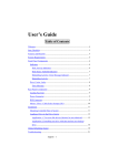
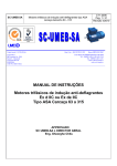
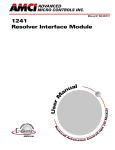
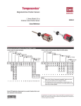
SERIES 7500 INTELLIGENT LDT INTERFACE MODULE
Overview
This manual explains the installation and operation of the
7551 LDT Interface Module.
Utilizing licensed Allen-Bradley SLC 500™ I/O interface technology, the one slot 7551 LDT Interface Module
accepts one transducer input and plugs directly into the
A-B SLC 500 rack. Communicating through I/O
registers assigned to the slot, the module supplies absolute position and velocity data to A-B SLC™ processors
from AMCI, Balluf or Temposonics™ II magnetostrictive linear displacement transducers (LDTs).
Front Panel Description
Two LEDs on the front panel shows the modules'
operating status.
LDT
INTERFACE
7551
RUN - This green LED is on
when the module is operational.
FAULT - This red LED is
blinking when there is a transducer fault, or on when there is a
module fault. There are four
major causes of a transducer
fault.
• Broken transducer cable.
• Non-compatible transducer.
• Improperly wired transducer
cable.
• Faulty transducer.
The transducer input connector, located behind the
module door, accepts the 8 pin Phoenix connector
(AMCI Part # MS-8) from the transducer cable. The
transducer cable wiring diagram is shown under "Cable
Installation". The 7551 uses the following transducers:
• AMCI LHT Series LDT
• MTS Temposonics II LDT with DPM or RPM
Personality Modules
• Balluff LDT with 'K2' output / power supply
option.
The 7551 module requires an external ±15 Vdc supply
for LDT operation. Power supply current rating is
based on the actual LDT.
ADVANCED
MICRO CONTROL S INC.
Table of Contents
Overview .................................................... 1
Front Panel Description.............................. 1
Installation .................................................. 2
Power Requirements
Velocity Response Setup
Rack Installation
Compatible Transducers
Temposonics DPM Setup
Transducer Mounting
LDT Power Supply
Cable Installation
Software Configuration ................................ 4
7551 Programmable Parameters ................ 4
Data Format ................................................ 5
Programming from the Processor .............. 6
Important User Information ....................... 8
Standard Warranty ...................................... 8
Returns Policy ............................................ 8
24 Hour Technical Support Number .......... 8
Revision History ......................................... 8
Plymouth Industrial Park, Terryville CT 06786
Tel: (203) 585-1254 Fax: (203) 584-1973
SERIES 7500 INTELLIGENT LDT INTERFACE MODULE
Installation
Power Requirements
Rack Installation
The 7551 requires 0.215A @ 5Vdc. Add this
to the current requirements of your system
when sizing the system power supply. Note
that this requirement excludes the use of some
modules with the 7551 in fixed SLC 500
systems.
Velocity Response Setup
A jumper on the 7551 determines how often
the module updates the velocity data. With the
jumper installed velocity data updates every
120 mSec. Removing the jumper sets the
velocity update to 32 mSec. The figure below
shows the placement of the jumper on the
7551 module.
Velocity Response Jumper
Installed: 120 mSec Update Time
Removed: 32 mSec Update Time
Shown with Jumper installed.
U2
JP1
JP1
You can install the 7551 in any free slot as
long as power requirements are met. Align the
modules' circuit board with the top and bottom
card guides in the rack and gently slide the
module into the rack until the top and bottom
latches secure the module in place.
To remove the module, depress the top and
bottom latches and slide the module out of the
rack.
Compatible Transducers
The 7551 is designed for use with AMCI's
LHT Series transducers and has been tested
with Temposonics II and Balluff LDTs.
Temposonics II LDTs must have an RPM or
DPM Personality Module and Balluff LDTs
must have the 'K2' output / power supply option.
Temposonics DPM Setup
The DPM Personality Module has switches
that set the number of recirculations and the
interrogation type. When using a DPM Module, set Switch SW1 to '4' (4 Recirculations)
and SW2 to '8' (External Interrogation).
Transducer Mounting
Refer to the documentation you recieved with
your LDT to properly mount the transducer.
LDT Power Supply
The 7551 requires a ±15 Vdc power supply for
LDT operation. MTS offers a ±15 Vdc @
0.8A supply for use with their transducers.
MTS Part Number is 380017.
UNDER NO CIRCUMSTANCES is the
-15 Vdc supply, commonly marked '-15 V', to
be connected to Power Supply or Earth Grounds.
Doing so can damage the power supply, the LDT,
and the 7551 module.
2
ADVANCED
MICRO CONTROL S INC.
SERIES 7500 INTELLIGENT LDT INTERFACE MODULE
Installation (cont'd)
Cable Installation
Cables can be ordered directly from the LDT manufacturer. Optionally, MTS specifies BELDEN #8105 for
use as an extention cable.
The following figures are wiring diagrams for Balluff and Temposonics II transducers. Follow the LDT
manufacturers' guidelines for maximum cable length and installation.
Overall Shield
8
7
6
5
4
3
2
1
+ STOP
- STOP
GRAY
GREEN
PINK
- INTERROGATE
YELLOW
+ INTERROGATE
SHIELDS
SHIELDS
WHITE
- 15 Vdc
BLUE
+ 15 Vdc
BROWN
SUPPLY GROUND
Module Connector
AMCI Part #: MS-8
Phoenix #: MSTB1.5/8-ST-5.08
+15V
GND
-15V
±15Vdc Power Supply
AMCI and Balluff LDT Cable Drawing
Overall Shield
Module Connector
AMCI Part #: MS-8
Phoenix #: MSTB1.5/8-ST-5.08
8
7
6
5
4
3
2
1
BELDEN CABLE #8105 or exact equ.
* + START/STOP
- START/STOP
ORANGE/WHT
WHITE/ORN
GRAY/WHT
- INTERROGATION
WHITE/GRY
+ INTERROGATION
SHIELDS
SHIELDS
GREEN/WHT
- 15 Vdc
WHITE/BLU
+ 15 Vdc
WHITE/GRN
DC GROUND
BLUE/WHT
FRAME GND
BROWN/WHT
WHITE/BRN
+15V
GND
* Cable for Transducers with RPM Personality Module is shown.
For Transducers with DPM Personality Module, the following pins are renamed:
+ Start/Stop renamed to + Gate Out
- Start/Stop renamed to - Gate Out.
-15V
±15Vdc Power Supply
Temposonics II LDT Cable Drawing
Plymouth Industrial Park, Terryville CT 06786
Tel: (203) 585-1254 Fax: (203) 584-1973
3
SERIES 7500 INTELLIGENT LDT INTERFACE MODULE
Software Configuration
Before the 7551 can communicate with the SLC processor, you must program the proper ID Code into the programmable controller's processor file using a Hand Held Terminal or APS software. The ID Code for the 7551 is
3515. This ID Code reserves 8 Input and 8 Output words for the module. Refer to your A-B manuals for explicit
instructions on entering ID Codes with the HHT or APS software.
If you are using ICOM's A.I. Series™ Programming Software it must be version 7.03 or above.
A lower version number will not allow you to set the ID Code as high as 3515.
7551 Programmable Parameters
The 7551 gives tremendous flexibility in scaling the position and velocity data to meaningful values for your
application. An example of a common application for LDTs is measuring the amount of liquid in a tank. With
the 7551 you can scale the position to read out directly in gallons, either in the tank or dispensed, and velocity
data to read out in gallons dispensed per second.
The 7551 has many programmable Parameters to achive this flexibility. Below is a listing with a brief
explanation and default values.
LDT Type - Specifies the type of LDT, AMCI, Balluff or Temposonics, attached to the 7551. Defaults
to AMCI.
Connection Type - Specifies the type of Personality Module, RPM or DPM, in the Temposonics LDT.
Default value of RPM.
Measurement Unit - Specifies the measurement unit for the Full Scale Length parameter and effects
the values that can be entered for Full Scale Count. If the LDT Type is Temposonics, this parameter
also effects the value of the LDT Gradient. Default value of Inches and Temposonics LDT Gradient
specified in µSec/inch. AMCI and Balluff LDT Gradients are always specified in meters/second.
LDT Gradient - This is a calibration parameter supplied by the LDT manufacturer. MTS specifies the
gradient in µSec/inch or µSec/mm while Balluff specifies it in meters/second. The gradient value
need not be programmed for operation but accuracy will suffer. Default value of 2813 meters/sec.
Full Scale Length - Most commonly set to the expected length of travel, the Full Scale Length can
actually be any value that simplifies the Full Scale Count value. Based on the Measurement Unit
setting, the range of values is 2 to 327 inches or 50 to 8305 millimeters. Default value of 16 inches.
Full Scale Count - Sets the number of counts over the specified Full Scale Length. The range of values
is 2 to (Full Scale Length * 1000) if Measurement Unit is inches or 2 to (Full Scale Length * 10) if
Measurement Unit is millimeters. Default value of 16000. (Resolution equals 0.001 inches)
Preset Value - Allows you to set the Position (starting count) of the LDT when at its home position.
The range of values is -999,999 to +999,999. Note that changing the Preset Value does not set the
Position to the specified value. The Position is preset only if the PRESET LDT Bit, Output Word 0 /
Bit 0, is set to '1' during a program transfer. Default value of zero.
Count Direction - Specifies the direction, relative to the head of the LDT, the magnet must travel to
increment the position count. Setting the direction positive forces the position count to increment as
the magnet travels away for the LDT head. Setting the direction negative forces the position count
to increment as the magnet travels toward the LDT head. Default direction is positive.
4
ADVANCED
MICRO CONTROL S INC.
SERIES 7500 INTELLIGENT LDT INTERFACE MODULE
Data Format
The format of the position, velocity, and fault diagnostics, is shown below. A fault diagnostic bit is set to '1' to
indicate an error. Errors can be Software Errors, set when parameters are incorrect, or Hardware Errors, set when
there is a hardware failure or a parameter is valid but will not work with the hardware. An example of this is setting
the Connection Type to RPM when there is a DPM Module in the LDT. Position and velocity data is transferred in
two words. The first word of data contains the upper three or four digits of the value, while the second word
contains the bottom three digits of the value. For example, let the position data equal 31,416. The first word of
position data contains the binary number 31, and the second word contains the binary number 416. If the position
data is negative, data is transfered in sign-magnitude format.
0
0
0
0
0
0
Lower 3 digits: Position Value
Word 3
0
0
0
0
0
0
Upper 3 digits: Velocity Value
Word 4
0
0
0
0
0
0
Lower 3 digits: Velocity Value
Word 2
LEN Err
0
0
Gradient
Err
0
0
FSC Err
0
0
DIR Err
0
Word 1
0
PRESET
Err
E² Err
0
Word 0
SPIOGA
ACK
LDT Err
0
POS Sign
MSG IGN
15 14 13 12 11 10 09 08 07 06 05 04 03 02 01 00
Upper 3 or 4 digits: Position Value
WORDS 5-7 RESERVED: Set to zero
Word 0:
Bit 0: Gradient Error - Set when Gradient Value is outside the expected range. Causes for this error are
incorrect gradient value or incorrect GRAD TYPE or Measurement UNIT bits in Output Word 0.
Bit 1: Length Error - The Full Scale Length is outside the expected range. Range of Length values are 2 to
327 inches or 50 to 8305 millimeters. Note that this error can be caused by setting the Length greater
than 327 mm and having the Measurement unit specified as inches.
Bit 2: Full Scale Count Error - The Full Scale Count is not in the range of 2 to (Length * 1000) if Measurement Unit is specified as inches or 2 to (Length * 10) if Measurement Unit is specified as millimeters.
Bit 3: Position Preset Error - Set when Preset Value is outside the range of -999,999 to 999,999.
Bit 4: Direction Error - Set when +DIR and -DIR bits are both set to '1'.
Bit 6: SPIOGA Error - Set on SPIOGA communications error.
Bit 7: Message Ignored - If an error bit is set, the error must be cleared by programming the effected
parameter. This bit is set if you attempt to program a different parameter before clearing the error.
Bit 12: E² Error - Set on EEPROM Memory Fault.
Bit 14: LDT Error - Set on Transducer Fault. This error can be caused by improperly programming the
Connection Type parameter, a faulty transducer or improper installation.
Bit 15: Acknowledge Bit - Used to acknowledge a program transfer.
Word 1:
Bit 15: Position Sign - Set when position value is negative.
Plymouth Industrial Park, Terryville CT 06786
Tel: (203) 585-1254 Fax: (203) 584-1973
5
SERIES 7500 INTELLIGENT LDT INTERFACE MODULE
Programming from the Processor
Use the eight Output Words assigned to the 7551 to control the module from the backplane. With these words
you can:
• Clear an EEPROM Memory Error
• Change the programmable parameters listed on page 4.
• Preset the position count.
The format of the 8 Output Words is shown below. To program the module, write the new values into the correct
registers, set the proper bits in Output Word 0, and set the Transmit bit (TRMT) to 1. The 7551 accepts new
parameters only on a 0Ž1 transition of the TRMT bit. LDT Gradient, Full Scale Count and Preset Value are
transferred in two words. The first word of data contains the upper one, two or three digits of the value, the second
word contains the bottom three digits of the value. For example, let the Full Scale Count equal 39,370. The first
word of position data contains the binary number 39, and the second word contains the binary number 370. If the
Preset Value is negative, set the Preset Sign bit (Word 6, Bit 15) and transfer the magnitude of the value in the
digits.
0
0
0
+ DIR
- DIR
Measure
UNIT
CONN
TYPE
LDT
TYPE
LDT
SETUP
PRESET
LDT
E² CLR
LENGTH
TRMT
0
0
0
0
0
0
0
0
0
0
0
0
0
0
0
Word 3
0
0
Word 4
0
0
0
0
0
0
0
Word 5
0
0
0
0
0
0
Lower 3 digits: Full Scale Count
Word 6
PRESET
SIGN
PRESET
VALUE
FS
COUNT
15 14 13 12 11 10 09 08 07 06 05 04 03 02 01 00
0
0
0
0
0
Upper 3 digits: Position Preset
Word 7
0
0
0
0
0
0
Lower 3 digits: Position Preset
Word 0
Word 1
Word 2
0
Upper 1 or 2 digits:
LDT Gradient
Lower 3 digits: LDT Gradient
Full Scale Length
Upper 3 digits:
Full Scale Count
Word 0:
Bit 0: PRESET LDT - Set the position count to the Preset Value.
Bit 1: LDT Setup - Set this bit to '1' to program the LDT Type (Bit 2), Connection Type (Bit 3), Measurement Unit (Bit 4) and LDT Gradient (Words 1 and 2). When set to '0', Bits 2,3,4 and LDT Gradient
are not read.
6
ADVANCED
MICRO CONTROL S INC.
SERIES 7500 INTELLIGENT LDT INTERFACE MODULE
Programming from the Processor (cont'd)
Word 0: (cont'd)
Bits 2/3: LDT Type and Connection Type - Set these bits according to the table below.
CONN
0
0
1
1
LDT
0
1
0
1
Temposonics LDT with DPM Module
AMCI LHT Series LDT
Temposonics LDT with RPM Module
Balluff LDT with K2 output / power supply option
Bit 4: Measurement Unit - Set to '0' when programming the Full Scale Length in Inches and Temposonics
LDT Gradient in µSec/inch. Set to '1' when programming the Full Scale Length in millimeters and the
Temposonics LDT Gradient in µSec/mm.
Bit 5: Full Scale Length - Set this bit to '1' to change the Full Scale Length to the value in Output Word 3.
Bit 6: Full Scale Count - Set this bit to '1' to change the Full Scale Count to the value in Output Words 4
and 5.
Bit 7: Preset Value - Set this bit to '1' to change the Preset Value to the number in Output Words 6 and 7.
Note that this does not preset the position count. (See PRESET LDT Bit 0.)
Bits 8/9: Negative Direction and Positive Direction - Set these bits according to the table below.
+ DIR
0
0
1
1
- DIR
0
1
0
1
Remain at last programmed value.
Count increase for travel towards LDT head.
Count increase for travel away from LDT head.
Error condition. DIR Err Bit set. (Input Word 0, Bit 4)
Bit 14: E²PROM Clear - Set to clear an E²PROM Memory Fault or reset all parameters to default values.
Bit 15: Transmit Bit - 0Ž1 transition on this bit initiates a program transfer.
On a 0 Ž1 transition of the TRMT bit the 7551 will process the commands in the following order shown
below. If the module encounters an error it will set the approprite bit and stop processing the commands.
1)
2)
3)
4)
5)
Clear EEPROM Memory Fault
LDT and Connection Type
Measurement Unit
LDT Gradient
Full Scale Length
6)
7)
8)
9)
Full Scale Count
Direction
Preset Value
Preset Position
Once the 7551 has accepted and processed the commands, it will set/reset the appropriate fault diagnostic bits
and then set the ACKnowledge Bit. Once the ACK bit is set, check the error bits in Word 0 of the Input
Registers and then write 0000 into Word 0 of the Output Registers. This resets the TRMT bit. The module
will respond by resetting the ACK bit. The programming cycle is now complete and a new cycle can begin.
The EEPROM is guaranteed for approximately 10,000 write cycles before writing to
it will cause a fault. Therefore continuously presetting the position or writing new
parameters should be avoided. If your application requires you to continuously
preset the position, consider calculating and applying the required position offset in
the PLC program.
Plymouth Industrial Park, Terryville CT 06786
Tel: (203) 585-1254 Fax: (203) 584-1973
7
SERIES 7500 INTELLIGENT LDT INTERFACE MODULE
Important User Information
This product incorporates technology which is licensed by Allen-Bradley Company, Inc. Allen-Bradley has not
technically approved, nor does it warrant or support this product. All warranty and support for this product and its
application is provided solely by Advanced Micro Controls, Inc.
The products and application data described in this manual are useful in a wide variety of different applications.
Therefore, the user and others responsible for applying these products described herein are responsible for determining
the acceptability for each application. While efforts have been made to provide accurate information within this
manual, AMCI assumes no responsibility for the application or the completeness of the information contained herein.
UNDER NO CIRCUMSTANCES WILL ADVANCED MICRO CONTROLS, INC. BE RESPONSIBLE OR LIABLE
FOR ANY DAMAGES OR LOSSES, INCLUDING INDIRECT OR CONSEQUENTIAL DAMAGES OR LOSSES,
ARISING FROM THE USE OF ANY INFORMATION CONTAINED WITHIN THIS MANUAL, OR THE USE OF
ANY PRODUCTS OR SERVICES REFERENCED HEREIN.
No patent liability is assumed by AMCI, with respect to use of information, circuits, equipment, or software described
in this manual.
The information contained within this manual is subject to change without notice.
™SLC and SLC 500 are trademarks of the Allen-Bradley Company. Temposonics is a trademark of MTS Systems
Corp.
Standard Warranty
ADVANCED MICRO CONTROLS, INC. warrants that all equipment manufactured by it will be free from defects,
under normal use, in materials and workmanship for a period of [1] year. Within this warranty period, AMCI shall, at
its option, repair or replace, free of charge, any equipment covered by this warranty which is returned, shipping charges
prepaid, within one year from date of invoice, and which upon examination proves to be defective in material or
workmanship and not caused by accident, misuse, neglect, alteration, improper installation or improper testing.
The provisions of the “STANDARD WARRANTY” are the sole obligations of AMCI and excludes all other warranties
expressed or implied. In no event shall AMCI be liable for incidental or consequential damages or for delay in performance of this warranty.
Returns Policy
All equipment being returned to AMCI for repair or replacement, regardless of warranty status, must have a Return
Merchandise Authorization number issued by AMCI. Call (860) 585-1254 with the model number and serial number
(if applicable) along with a description of the problem. A “RMA” number will be issued. Equipment must be shipped
to AMCI with transportation charges prepaid. Title and risk of loss or damage remains with the customer until shipment is received by AMCI.
24 Hour Technical Support Number
24 Hour technical support is available on this product. For technical support, call (860) 583-7271. Your call will be
answered by the factory during regular business hours, 8AM – 5PM EST, Monday through Friday. during non-business
hours, an automated system will ask you to enter the telephone number you can be reached at and a description of the
problem. Please remember to include your area code. The system will page the support engineer on call.
Revision History
This manual, 940-55060 is the first release of the electronic version of the 940-05060 manual. It was first released
10/12/98.
8
7500 Module Quick Start Guide
This supplement to the standard 7500 manual is a guide to setting up a 7500 LDT interface module.
It assumes that you are familiar with SLC500 processors and ladder logic programming. If you are
not, please see the appropriate Allen-Bradley literature, or contact your local AB representative.
1. Determine what kind of Linear Displacement Transducer, LDT, you are using. The following
table contains a list of compatible LDTs.
Manufacturer
AMCI
Balluff
Temposonic
LDT Part Number
LHTA-X, LHTB-X, or LHTC-X
BTL-2-K2-XXXX-X-XXXX-XX
TTS-XXXXXXXDE004
TTS-XXXXXXXR
LPXXSXXXXX
LHXXXXXXXXXXR0
LHXXXXXXXXXXDE-04
X = “don’t care”
2. Record the Gradient Value of the LDT. This calibration parameter is located on the transducer’s
head, and is necessary to calculate accurate position data. AMCI transducers will have a gradient
value in meters/second. Temposonic transducers will have a gradient value in msec/inch or
msec/millimeter. Depending on when it was manufactured, Balluff transducers may have their
gradient values in either meters/second or msec/inch. However, setting the 7500 module for
Balluff requires that the gradient be entered in meters/second. The following formula can be
used to convert from ms/in to m/s. Gradient in m/s = [1/(gradient in ms/in * 0.00003937)] The
result should be between 2541m/s and 3175m/s.
3. Determine your application requirements. This will include the required position resolution programmable up to 0.001”, the direction of travel - increasing position data as the magnet
moves away from or towards the head of the transducer, and the measurement unit - inches or
millimeters.
4. Wire the LDT and the external power supply into the MS-8 connector which plugs into the 7500
module. Please refer to page 3 of the manual for wiring information, and note that pin 1 is
located at the bottom of the connector when it is plugged into the module. AMCI, Balluff, and
Temposonic II transducers all require an external +15Vdc to operate. The Temposonic LP and
LH transducers require an external +15Vdc to +24Vdc to operate. The 7551 will operate
normally at the +24Vdc, but it is recommended that a +15Vdc supply be used. When wiring the
LP or LH transducers, pin three of 7551 module’s MS-8 connector, the -15Vdc input, should be
left open.
5. Configure the slot where the 7500 module will reside using your PLC programming software.
The 7500 module has an ID code of 3515.
6. The 7500 module is programmed from the output image table of the PLC. The data can either
be manually entered, or a ladder logic program can be generated to program the module. A
sample ladder logic program, with the module located in slot 1, is shown at the end of the Quick
Start guide. If you are using this program, and your module is located in a different slot, modify
the program to use your slot number.
7. With the 7500 module installed, power up your SLC500 rack and download your rack
configuration and ladder logic program to the PLC.
8. After verifying that the wiring is correct, plug the MS-8 connector into the 7500 module, and
power up the external supply. The unit’s green LED should be on solid, and the red LED either
off, or on flashing. The Red LED may be flashing because the transducer is improperly wired,
or the 7500 module has not yet been configured for the transducer type which you are using.
9. Enter the data that will be sent to the 7500 module. If you are using the sample program, the
following data should be entered in word N7:10.
Manufacturer
AMCI
Balluff
Temposonic
Temposonic
LDT Part Number
LHTA-X, LHTB-X, or LHTC-X
BTL-2-K2-XXXX-X-XXXX-XX
TTS-XXXXXXXDE004
LHXXXXXXXXXXDE-04
TTS-XXXXXXXR
LPXXSXXXXX
LHXXXXXXXXXXR0
N7:10 Data
(measurement
units in
inches)
6
14
2
N7:10 Data
(measurement
units in
millimeters)
22
30
18
10
26
X = “don’t care”
10. Enter the gradient value in words N7:11 and N7:12. If the gradient is in meters/second, its value
will be approximately 2813m/s. If this were the gradient, a 2 would be entered in word N7:11 and
813 in word N7:12. If the gradient value is in µsec/inch, its value will be approximately 9.0300
µs/in. If this were the gradient, a 90 would be entered in word N7:11 and 300 in word N7:12. If
the gradient value is in µsec/millimeter, its value will be approximately 0.3555 µs/mm. If this
were the gradient, a 3 would be entered in word N7:11 and 555 in word N7:12.
11. Once the data has been entered, initiate the transfer by manually setting word N7:0 to “1”. Once
the transfer is complete, the7500 module will respond by setting the ACKnowledge bit, input
word 0, bit 15, setting any error bits, and resetting N7:0 to 0. The programming cycle is now
complete, and the module is ready for operation.
12. The 7500 module has additional features which allow it to be configured for specific applications.
The users manual contains a complete description of these features and explains how to program
each of them. For example, the Full Scale Length and Full Scale Count Parameters (FSC) can be
used to program the module’s resolution. If you want 0.001” resolution, set the FSC to 1000
times the length. If you want 0.01” resolution, set the FSC to 100 times the length. The length
value is typically the transducer length, however, the module will not stop counting if the
position data exceeds the length value. When entering the FSC, please note that the value is
divided into two words. The upper word contains the 1000s places and the lower word contains
the 1s, 10s, and 100s places. For example, if the FSC value is 12,345, the upper word would be
12, and the lower word would the 345.
Programming Example
The three rung ladder logic program below can be, but does not have to be, used to program a 7500
module. This example assumes the module is located in slot 1 of the SLC rack and uses the following
addresses.
N7:0/0
N7:10 - N7:17
I:1.0/15
O:1.0/15
Manually set to initiate data transfer to the 7500 module.
Holds data written to the 7500 module at output words O:1.0 - O:1:7.
7500 ACKnowledge bit.
7500 Transmit bit.
Manually set bit N7:0/0 to initiate the transfer of data to the 7500 module. Note that the data in
N7:10 does not have transmit bit O:1/15 set. This rung is performed until acknowledge bit I:1/15 is
set.
Set to write to
7500 module
N7:0
7500
ACK bit
COP
I:1
0
15
COPY FILE
Source: #N7:10
Dest: #O:1.0
Length: 8
When bit N7:0/0 has been manually set, this rung sets transmit bit O:1/15, which tells the 7500
module to act on the data located in the output image table. This rung is true as long as bit N7:0/0 is
set, and the module has not responded by setting acknowledge bit I:1.0/15.
Set to write to
7500 Module
N7:0
0
7500
ACK bit
I:1
7500 Transmit
Bit
O:1
(
)
15
15
The following rung unlatches bit N7:0/0 when the 7500 module has set acknowledge bit I:1/15 in
response to the transmit bit being set in rung two. The Programming cycle is now complete.
Set to write to
7500 module
N7:0
0
7500
ACK bit
I:1
15
Document Number: 940-55010
Set to write to
7500 Module
N7:0
( U )
0