1
ORTEC
®
Model 921E
EtherNIM™ High-Rate
Multichannel Buffer
Hardware Manual
Printed in U.S.A.
ORTEC® Part No. 777610
Manual Revision F
0110
Advanced Measurement Technology, Inc.
a/k/a/ ORTEC®, a subsidiary of AMETEK®, Inc.
WARRANTY
ORTEC* warrants that the items will be delivered free from defects in material or workmanship. ORTEC makes no other
warranties, express or implied, and specifically NO WARRANTY OF MERCHANTABILITY OR FITNESS FOR A
PARTICULAR PURPOSE.
ORTEC’s exclusive liability is limited to repairing or replacing at ORTEC’s option, items found by ORTEC to be defective
in workmanship or materials within one year from the date of delivery. ORTEC’s liability on any claim of any kind, including
negligence, loss, or damages arising out of, connected with, or from the performance or breach thereof, or from the
manufacture, sale, delivery, resale, repair, or use of any item or services covered by this agreement or purchase order, shall in
no case exceed the price allocable to the item or service furnished or any part thereof that gives rise to the claim. In the event
ORTEC fails to manufacture or deliver items called for in this agreement or purchase order, ORTEC’s exclusive liability and
buyer’s exclusive remedy shall be release of the buyer from the obligation to pay the purchase price. In no event shall ORTEC
be liable for special or consequential damages.
Quality Control
Before being approved for shipment, each ORTEC instrument must pass a stringent set of quality control tests designed to
expose any flaws in materials or workmanship. Permanent records of these tests are maintained for use in warranty repair and
as a source of statistical information for design improvements.
Repair Service
If it becomes necessary to return this instrument for repair, it is essential that Customer Services be contacted in advance of
its return so that a Return Authorization Number can be assigned to the unit. Also, ORTEC must be informed, either in writing,
by telephone [(865) 482-4411] or by facsimile transmission [(865) 483-2133], of the nature of the fault of the instrument being
returned and of the model, serial, and revision ("Rev" on rear panel) numbers. Failure to do so may cause unnecessary delays
in getting the unit repaired. The ORTEC standard procedure requires that instruments returned for repair pass the same quality
control tests that are used for new-production instruments. Instruments that are returned should be packed so that they will
withstand normal transit handling and must be shipped PREPAID via Air Parcel Post or United Parcel Service to the designated
ORTEC repair center. The address label and the package should include the Return Authorization Number assigned.
Instruments being returned that are damaged in transit due to inadequate packing will be repaired at the sender's expense, and
it will be the sender's responsibility to make claim with the shipper. Instruments not in warranty should follow the same
procedure and ORTEC will provide a quotation.
Damage in Transit
Shipments should be examined immediately upon receipt for evidence of external or concealed damage. The carrier making
delivery should be notified immediately of any such damage, since the carrier is normally liable for damage in shipment.
Packing materials, waybills, and other such documentation should be preserved in order to establish claims. After such
notification to the carrier, please notify ORTEC of the circumstances so that assistance can be provided in making damage
claims and in providing replacement equipment, if necessary.
Copyright © 2010, Advanced Measurement Technology, Inc. All rights reserved.
*ORTEC® is a registered trademark of Advanced Measurement Technology, Inc. All other trademarks used herein are the
property of their respective owners.
TABLE OF CONTENTS
WARRANTY . . . . . . . . . . . . . . . . . . . . . . . . . . . . . . . . . . . . . . . . . . . . . . . . . . . . . . . . . . . . . . . . ii
Safety Instructions and Symbols . . . . . . . . . . . . . . . . . . . . . . . . . . . . . . . . . . . . . . . . . . . . . . . . . . iv
Safety Warnings and Cleaning Instructions . . . . . . . . . . . . . . . . . . . . . . . . . . . . . . . . . . . . . . . . . v
1. INTRODUCTION . . . . . . . . . . . . . . . . . . . . . . . . . . . . . . . . . . . . . . . . . . . . . . . . . . . . . . . . . . 1
1.1. About This Manual . . . . . . . . . . . . . . . . . . . . . . . . . . . . . . . . . . . . . . . . . . . . . . . . . . . . . 1
2. INSTALLATION . . . . . . . . . . . . . . . . . . . . . . . . . . . . . . . . . . . . . . . . . . . . . . . . . . . . . . . . . . . 3
2.1. Ethernet Connection (Not Supported by Vista) . . . . . . . . . . . . . . . . . . . . . . . . . . . . . . . 4
2.2. Cabling Up a System . . . . . . . . . . . . . . . . . . . . . . . . . . . . . . . . . . . . . . . . . . . . . . . . . . . . 4
3. TROUBLESHOOTING . . . . . . . . . . . . . . . . . . . . . . . . . . . . . . . . . . . . . . . . . . . . . . . . . . . . . . 7
3.1. Data or Settings Are Lost When Power Is Turned Off . . . . . . . . . . . . . . . . . . . . . . . . . . 7
4. SPECIFICATIONS . . . . . . . . . . . . . . . . . . . . . . . . . . . . . . . . . . . . . . . . . . . . . . . . . . . . . . . . . . 9
4.1. Front-Panel Indicators . . . . . . . . . . . . . . . . . . . . . . . . . . . . . . . . . . . . . . . . . . . . . . . . . . . 9
4.2. Connectors . . . . . . . . . . . . . . . . . . . . . . . . . . . . . . . . . . . . . . . . . . . . . . . . . . . . . . . . . . . . 9
4.3. Data Memory . . . . . . . . . . . . . . . . . . . . . . . . . . . . . . . . . . . . . . . . . . . . . . . . . . . . . . . . . . 9
4.4. Presets . . . . . . . . . . . . . . . . . . . . . . . . . . . . . . . . . . . . . . . . . . . . . . . . . . . . . . . . . . . . . . . 9
4.5. Interface Connectors (Rear-Panel) . . . . . . . . . . . . . . . . . . . . . . . . . . . . . . . . . . . . . . . . 10
4.6. ADC . . . . . . . . . . . . . . . . . . . . . . . . . . . . . . . . . . . . . . . . . . . . . . . . . . . . . . . . . . . . . . . . 10
4.7. Controls (Front-Panel) . . . . . . . . . . . . . . . . . . . . . . . . . . . . . . . . . . . . . . . . . . . . . . . . . 11
4.8. Digital Spectrum Stabilizer . . . . . . . . . . . . . . . . . . . . . . . . . . . . . . . . . . . . . . . . . . . . . . 11
4.9. Electrical and Mechanical . . . . . . . . . . . . . . . . . . . . . . . . . . . . . . . . . . . . . . . . . . . . . . . 11
4.10. Battery Backup . . . . . . . . . . . . . . . . . . . . . . . . . . . . . . . . . . . . . . . . . . . . . . . . . . . . . . 12
4.11. Feature Mask Bits . . . . . . . . . . . . . . . . . . . . . . . . . . . . . . . . . . . . . . . . . . . . . . . . . . . . 12
APPENDIX A. FIRMWARE COMMANDS AND RESPONSES . . . . . . . . . . . . . . . . . . . . . .
A.1. CONNECTIONS-32 . . . . . . . . . . . . . . . . . . . . . . . . . . . . . . . . . . . . . . . . . . . . . . . . . . . . .
A.2. Command Records . . . . . . . . . . . . . . . . . . . . . . . . . . . . . . . . . . . . . . . . . . . . . . . . . . . .
A.3. Percent Response Records . . . . . . . . . . . . . . . . . . . . . . . . . . . . . . . . . . . . . . . . . . . . . .
A.4. Dollar Response Records . . . . . . . . . . . . . . . . . . . . . . . . . . . . . . . . . . . . . . . . . . . . . . .
A.5. Command Catalog . . . . . . . . . . . . . . . . . . . . . . . . . . . . . . . . . . . . . . . . . . . . . . . . . . . .
15
15
15
16
19
19
APPENDIX B. DIGITAL SPECTRUM STABILIZATION . . . . . . . . . . . . . . . . . . . . . . . . . . . 55
B.1. Point Mode Stabilization . . . . . . . . . . . . . . . . . . . . . . . . . . . . . . . . . . . . . . . . . . . . . . . 55
B.2. Gauss Mode Correction . . . . . . . . . . . . . . . . . . . . . . . . . . . . . . . . . . . . . . . . . . . . . . . . 55
iii
Safety Instructions and Symbols
This manual contains up to three levels of safety instructions that must be observed in order to
avoid personal injury and/or damage to equipment or other property. These are:
DANGER
Indicates a hazard that could result in death or serious bodily harm if the safety
instruction is not observed.
WARNING Indicates a hazard that could result in bodily harm if the safety instruction is not
observed.
CAUTION Indicates a hazard that could result in property damage if the safety instruction is
not observed.
In addition, the following symbols may appear on the product:
DANGER–High Voltage!
ATTENTION–Refer to Manual
Please read all safety instructions carefully and make sure you understand them fully before
attempting to use this product.
iv
Safety Warnings and Cleaning Instructions
DANGER
Opening the cover of this instrument is likely to expose dangerous voltages.
Disconnect the instrument from all voltage sources before opening it.
WARNING Using this instrument in a manner not specified by the manufacturer may impair
the protection provided by the instrument.
Cleaning Instructions
To clean the instrument exterior:
! Remove loose dust on the outside of the instrument with a lint-free cloth.
! Remove remaining dirt with a lint-free cloth dampened in a general-purpose detergent and
water solution. Do not use abrasive cleaners.
CAUTION To prevent moisture inside of the instrument during external cleaning, use only
enough liquid to dampen the cloth or applicator.
v
vi
1. INTRODUCTION
The ORTEC Model 921E EtherNIM™ High-Rate Multichannel Buffer (MCB) is a two-wide
NIM module designed for high-rate and high-performance data acquisition in nuclear
spectroscopy applications. It offers the following functions:
! Digital Spectrum Stabilizer Ensures spectral stability over long counting periods and wide
ranges of count rate and temperature.
! Analog-to-Digital Circuit (ADC) High-speed, 16k-channel, successive-approximation
type with a conversion time of 1.5 µs at a rate of 100,000 counts/sec, measured at a 5-µs
shaping time with a Model 973 High-Rate Spectroscopy Amplifier.
! Data Memory The architecture of the Model 921E employs an 80386 microprocessor with
dual Direct Memory Access (DMA) channels to maximize system throughput. In data
memory, 1 bit is reserved for a region-of-interest (ROI) flag, leaving a net nonvolatile data
memory of 64,000 channels and 231!1 (over 2 billion) counts per channel.
! I/O Port TTL IN/TTL OUT primarily intended to facilitate interfacing to sample changers.
The Model 921E can be controlled with the accompanying MAESTRO®-32 MCA Emulation
Software or other ORTEC CONNECTIONS-32 compatible software packages. In addition, custom
control software can be developed with our CONNECTIONS-32 Programmers’ Toolkit (A11-B32).
The Model 921E occupies two slots of a NIM-standard bin and can be connected to the host PC
via the ORTEC Dual-Port Memory Interface or the legacy Ethernet interface. We recommend
using the ORTEC DPM-USB converter interface, which connects the 921E’s Dual-Port Memory
port to the PC’s high-speed USB port. Use an ac-powered USB hub to connect up to eight (8)
921Es as you wish (one USB-DPM per 921E) to a single PC.
Note that Microsoft® Windows® Vista™ does not support the 921E Ethernet interface.
1.1. About This Manual
This manual provides the information you will need to install and configure the Model 921E
hardware. For instructions on operating the 921E with ORTEC software applications, refer to
the software user manual.
! Chapter 2 tells how to install the software and hardware.
! Chapter 3 provides troubleshooting information.
! Chapter 4 lists the hardware specifications.
1
Model 921E EtherNIM™ High-Rate MCB
! The appendix of firmware commands and responses is intended for users who wish to write
custom software to control the Model 921E.
2
2. INSTALLATION
Do not connect the 921E to the PC until MAESTRO-32 has been installed.
1. Install the accompanying version of MAESTRO-32 (and the CONNECTIONS-32 Update Kit, if
included) according to its instructions. Depending on the 921E-to-PC interface(s) you will
use, mark the appropriate checkbox(es) on the installation wizard’s Instrument Family page
as follows:
! If using a DPM-USB interface converter to attach the 921E to the PC, mark the DPMUSB checkbox.
! If using only the Ethernet interface (and no ORTEC instruments with other types of
interfaces are connected to your PC), no selection is required in the installation wizard.
2. Turn off the bin power supply and install the Model 921E in the bin.
3. Cable the spectroscopy system components together.
! DPM-USB interface — Attach the DPM-USB converter’s 37-pin connector to the rear
panel of the 921E.
! Ethernet interface — If connecting via Ethernet, see Section 2.1.
4. Turn on the bin power. The µP Busy LED on the front panel of the Model 921E should light
brightly for a few seconds and then go out.
5. Connect the powered-on 921E to the system:
! DPM-USB interface — Connect to PC’s USB port or to an ac-powered hub hosted by
the PC. The Windows “found new hardware” wizard will open. Follow the prompts,
choosing to (a) not go to the Internet or the Microsoft website to find the driver, and (b)
automatically locate the driver. If the wizard cannot locate the driver, direct it to
C:\Program Files\Common Files\ORTEC Shared\UMCBI.
! Ethernet interface — Connect to either the PC’s LAN card or to a powered Ethernet
hub. This connection method does not open a Windows “found new hardware” wizard.
6. Run the MCB Configuration program to build the list of available detectors, according to the
MAESTRO User’s Manual.
DPM-USB users note: The 921E/DPM-USB combination you have just created is treated as
a distinct entity by MCB Configuration. If you disconnect this 921E from the system, then
3
Model 921E EtherNIM™ High-Rate MCB
reconnect via a different DPM-USB converter, you will have to re-run the MCB
Configuration program to reestablish communication between the 921E’s inputs and ORTEC
CONNECTIONS-32 software applications.
7. You are now ready to start MAESTRO-32 and use its Acquire/MCB Properties... dialog
and the 921E’s front-panel controls to set the data acquisition parameters for each input.
2.1. Ethernet Connection (Not Supported by Vista)
This option requires a PC running under Windows 2000 Professional SP4 or Windows XP
Professional SP2 or higher, and any Ethernet card that supports 10BASE2.
! Referring to the accompanying ORTEC MCB CONNECTIONS-32 Hardware Property Dialogs
Manual (P/N 931001, supplied either as hardcopy or in the \Manuals folder on the
installation disk), set the PC’s network protocol to IPX/SPX Compatible.
! Connect the Model 921E to the rear-panel ETHERNET connector using 50 Ω coaxial cable.
Be certain that a BNC T-connector and 50 Ω terminator are at each end of the cable.
! Power on the 921E.
! To control multiple 921Es from a single PC via the Ethernet interface, simply chain all
921Es together into a single LAN using BNC T-connectors at each 921E. (Don’t forget the
50 Ω terminator required at the last 921E in the chain and at the PC.) The MCB
Configuration program handles all the details of identifying each detector, and allows you
the option of modifying each one’s identification string.
2.2. Cabling Up a System
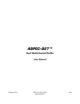
The standard cabling of a Model 921E system is shown in Fig. 1. If you have a detector that uses
a transistor-reset preamplifier (TRP) — that is, a “-Plus” model — all connections shown should
be made.
If using a resistive-feedback preamplifier (that is, a detector without a “-Plus” model
designation), the 132 INHIBIT GENERATOR does not exist, so do not make the connection to
TRP INH.
4
2.INSTALLATION
Figure 1. MERCURY (Models 973U/921E) System Interconnections.
5
Model 921E EtherNIM™ High-Rate MCB
6
3. TROUBLESHOOTING
3.1. Data or Settings Are Lost When Power Is Turned Off
The memory in the Model 921E has battery backup to maintain data when power is removed
from the module. It uses a lithium battery with a nominal voltage of 3.6 V specified in
Section 4.10.
To test the battery voltage, remove the left side panel (as viewed from the front). The voltage
can be measured at the battery cable connector near the top rear of the printed wiring board
(PWB). The voltage measured between the outer two pins of the 3-pin connector should be
>2 V. If <2 V, the battery needs be replaced to maintain battery back-up.
To replace the battery, locate the battery behind the top of the front panel. Twist or pry it loose
from the hook-and-loop fastener strip and unplug the wire connector. Replace with the new
battery (placing a strip of paper temporarily between the battery and the hook-and-loop fastener
strip may help in positioning the battery).
7
Model 921E EtherNIM™ High-Rate MCB
8
4. SPECIFICATIONS
4.1. Front-Panel Indicators
µP BUSY Red, busy-rate LED; intensity indicates the relative activity of the microprocessor.
STAB BUSY Red LED indicates when the stabilizer is active.
ADC BUSY Red, busy-rate LED flashes once for each pulse digitized by the ADC.
4.2. Connectors
INPUT Accepts positive-unipolar, positive-gated-integrator, or positive-leading-bipolar analog
pulses in the dynamic range from 0 to +10 V with a +12 V maximum; semi-Gaussian-shaped or
gated-integrator-shaped time constants from 0.25 to 30 µs, or delay-line-shaped with width
>0.25 µs. Zin >1 kΩ, dc-coupled. No internal delay. BNC connectors on front and rear panels.
ADC GATE Optional, slow-positive NIM input. Computer-selectable coincidence or anticoincidence. Signal must occur prior to and extend 0.5 µs beyond peak detect. Front-panel BNC
connector. The ADC GATE has no effect on the live-time correction circuitry.
PUR (Pileup Rejector) Rear-panel BNC connector accepts slow-positive NIM signal. Signal
must occur before ADC peak detect. Zin >1 kΩ.
BUSY Busy input used by live-time correction circuits. Accepts slow-positive NIM signal, Zin
>1 kΩ. BNC connector on rear panel.
CNG SMPL (Change Sample) TTL output signal, software addressable on rear-panel BNC.
SMPL RDY (Sample Ready) TTL input signal, software readable on rear-panel BNC.
4.3. Data Memory
16k channels of nonvolatile data memory; 231–1 (over 2 billion) counts per channel.
4.4. Presets
Real Time/Live Time Selectable in multiples of 20 ms.
Region-of-Interest Peak Peak count.
9
Model 921E EtherNIM™ High-Rate MCB
Region-of-Interest Integral Integral count selectable to a maximum value of 232–1 (over 4
billion).
Data Overflow Terminates acquisition when data in any channel exceeds 231–1 (over 2 billion)
counts.
Statistical Allows setting the required statistical accuracy on a key peak (for example, stop
counting when the activity of 60Co is known to be better than 5%).
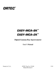
MDA Stops data collection when the value of the minimum detectable activity (MDA) for a
user-specified MDA nuclide reaches the needed value. The MDA preset is implemented in the
hardware. The formula for the MDA can be represented as follows:
The MDA value is calculated in the MCB given the constants a, b, and c. Counts is the gross
counts in the specified region and Live time is the live time. The constants a, b, and c, and the
total left-hand factor (expected value) are loaded into the MCB by the user. The calculated value
(right-hand side) is compared with the expected value and when it is lower, acquisition is
stopped.
4.5. Interface Connectors (Rear-Panel)
DUAL PORT MEMORY ORTEC dual-port interface, 37-pin D connector.
RS232C Standard, serial, male RS-232-C, 25-pin; wired as DTE to run at 38.4k baud
maximum, with modem control. (For diagnostics.)
ETHERNET Rear-panel BNC connector, accepts IEEE 802.3 10BASE2 (thin-wire coax).
4.6. ADC
Successive-approximation ADC with sliding-scale linearization, 16,000-channel resolution;
software selectable as 16k, 8k, 4k, 2k, 1k, and 512 channels.
Dead Time per Event 1.5 µs, including memory transfer (measured at 5-µs shaping with
ORTEC Model 973 High-Rate Spectroscopy Amplifier at 100,000 counts/sec input count rate).
Integral Nonlinearity #±0.025% over 99% dynamic range.
10
4. SPECIFICATIONS
Differential Nonlinearity #±1% (typical).
Gain Instability #±50 ppm/EC.
Dead-time Correction Extended live-time correction according to the Gedcke-Hale method.1
4.7. Controls (Front-Panel)
ADC LLD Screwdriver potentiometer adjust lower-level discriminator from 0–10% full scale.
ADC ZERO Screwdriver potentiometer adjusts ADC zero offset ±250 mV.
4.8. Digital Spectrum Stabilizer
ADC Data Word Size 14 bits (16k channels) maximum.
Stabilization Peak centroid (zero and gain) channel 2 to 16384; stabilization window width
(zero and gain) from ±1 to ±256 channels.
Correction Resolution At 16k ADC resolution: 0.04 channels for gain; <0.08 channels for
zero.
Setup/Enable/Disable From computer.
4.9. Electrical and Mechanical
Dimensions NIM-standard two-wide 6.90 × 22.13 cm (2.70 × 8.714 in.) front panel per
DOE/ER-0457T.
Weight
Net 2.25 kg (5 lb).
Shipping 3.1 kg (7 lb).
Power Requirements +24 V, 160 mA; !24 V, 240 mA; +12 V, 900 mA; !12 V, 260mA;
+6 V, 1.0 A. An ORTEC Model 4001A/4002D NIM Bin/Power Supply is recommended for up
to five Model 921E units. The ORTEC Model 495 Power Supply is available for NIM bins that
do not have 6 V power.
1
Ron Jenkins, R. W. Gould, and Dale Gedcke, Quantitative X-Ray Spectrometry (New York: Marcel Dekker,
Inc.), 1981, pp. 266–267.
11
Model 921E EtherNIM™ High-Rate MCB
4.10. Battery Backup
The memory in the Model 921E has battery backup to maintain data when power is removed
from the module.
Battery High-energy lithium, 3.6 V, ORTEC P/N 739460.
4.11. Feature Mask Bits
The following table describes the feature bits from the SHOW_FEATURES command discussed
on page 39. If the feature is supported in the Model 921E, the bit will be set to 1; if the feature is
not supported, the bit will be 0.
Bit
0
1
2
3
4
5
6
7
8
9
10
11
12
13
14
15
16
17
18
19
20
12
Meaning
Software-selectable conversion gain
Software-selectable coarse gain
Software-selectable fine gain
Gain stabilizer
Zero stabilizer
PHA mode functions available
MCS mode functions available
List mode functions available
Sample mode functions available
Digital Offset (e.g., 920)
Software-selectable Fine Offset (e.g., DART®)
HV power supply
Enhanced HV (SET_HV, SET/SHOW_HV_POL, SHOW_HV_ACT)
Software-selectable HV range (ENA_NAI, DIS_NAI)
Auto PZ (START_PZ_AUTO)
Software-selectable manual PZ (SET/SHOW_PZ)
Internal clock (SHOW_DATE/TIME, SHOW_DATE/TIME_START)
Sample Changer support (SET/SHOW_OUTPUT, SHOW_INPUT)
One-button acquisition (ENA/DIS/SHOW_TRIG_SPEC, MOVE)
Nomadic (likely to move between opens)
Local app data (SET_DATA_APP, SHOW_DATA_APP)
APPENDIX C. FEATURE MASK BITS
Bit
21
22
23
24
25
26
27
28
29
30
31
32
33
34
35
36
37
38
39
40
41
42
43
44
45
46
47
48
49
50
51
52
Meaning
Software-retrievable serial number
Power management commands
Battery status support
Software-selectable AMP polarity (SET/SHOW_GAIN_POLAR)
Support for flattop optimization (ENA/DIS_OPTI)
Stoppable AutoPZ
Network support (i.e., 92X-II)
Multi-drop serial support (e.g., RS-485)
Software-selectable DPM address
Multiple devices (e.g., 919)
Software-selectable ADC gate mode (SET_GATE...)
Downloadable firmware
Time histogram functions available (e.g., 9308)
Software-selectable Lower level disc
Software-selectable Upper level disc
MCS-mode SCA input available
MCS-mode positive TTL input available
MCS-mode fast-negative NIM input available
MCS-mode discriminator input available
Software-switchable discriminator edge
Software-programmable discriminator level
Software-programmable SCA upper and lower thresholds
Software-selectable MCS-mode input sources
Statistical preset
Features vary by input (SHOW_FEATURES depends on device/segment)
Software-selectable HV shutdown mode
Software-selectable shaping time constants
Explorable shaping time constants (SHOW_CONFIG_SHAP)
Advanced shaping time (SET_SHAP_RISE, SET_SHAPE_FLAT, etc.)
Software-selectable BLR (ENA/DIS/SHO_BLR_AUTO SET/SHO/VERI_BLR)
SHOW_STATUS command supported (returns $M record)
Overflow preset (ENA/DIS/SHO_OVER_PRES)
13
Model 921E EtherNIM™ High-Rate MCB
Bit
53
54
55
56
57
58
59
60
61
62
63
64
65
66
67
68
69
70
127
14
Meaning
Software-enabled audio clicker (ENA/DIS_CLICK)
Software-readable thermistor (SHOW_THERM)
Fine Gain is float number (SET/SHO/VERI/LIST_GAIN_FINE)
Software-enabled Pile-up Rejector. (ENA/DIS/SHO_PUR, SET_WIDT_REJ)
Alpha-style HV power (SHOW_HV_CURRENT)
Software-readable vacuum (SHOW_VACUUM)
Acquisition alarms (ENA/DIS_ALARM)
Hardware acquisition trigger (ENA/DIS_TRIG)
Ordinal shaping times (SET_SHAP 0, SET_SHAP 1, ...)
Query gain ranges (LIST/VERI_GAIN_FINE, ..._COAR, ..._CONV)
Routable inputs (SET/SHOW_INPUT_ROUTE)
External dwell support (ENA/DIS_DWELL_EXT)
Selectable SUM or REPLACE MCS modes (ENA/DIS_SUM)
External Start support (ENA/DIS/SHO_START_EXT)
Explorable MCS (LIST_SOURCE, LIST_LLSCA & LIST_ULSCA)
Device support the MDA preset (DSPEC and 92X-II)
Software-selectable ADC type (Matchmaker™)
Has ability to daisy-chain MCBs (DART®)
Extended feature mask available (SH_FEAT_EXT)
APPENDIX A. FIRMWARE COMMANDS AND
RESPONSES
Software communication with the 921E takes place through the CONNECTIONS-32 software
layer. CONNECTIONS-32 is used by all ORTEC software and is available for other software
development with our CONNECTIONS-32 Programmer’s Toolkit with Microsoft® ActiveX®
Controls (A11-B32).
A.1. CONNECTIONS-32
In CONNECTIONS-32, the communication consists of sending command records to the MCB API
and receiving response records from the MCB API. Both command and response records consist
of a sequence of printable ASCII characters followed by an ASCII carriage return. The single
exception to this rule is the “#B” response record for the WRITE command, which contains
binary integer numbers. All commands eventually respond with a percent response record (so
named because the response begins with an ASCII percent sign “%”) which signifies the
completion of the command. SHOW and STEP commands respond with a dollar response record
(which begins with an ASCII dollar sign “$”) followed by a percent response record. The
WRITE command can respond with multiple pound sign records (which begin with an ASCII
pound sign “#”) but eventually completes by sending a percent response record. All other
commands result in a single percent response record upon completion.
A.2. Command Records
Model 921E commands consist of a command header, which may be followed by numeric
parameter values. The header consists of a verb or a verb and noun separated by an underscore
or a verb, noun, and modifier, each separated by underscores. The verbs, nouns, and modifiers in
the command header are mnemonic words such as the verb ENABLE or the noun OVERFLOW
that relate to the function performed by the MCB when it executes the command. The first four
letters of any word will always be enough to uniquely identify the word when composing
commands for an MCB. For example, the command ENABLE_OVERFLOW_PRESET can be
abbreviated to ENAB_OVER_PRES.
Numeric parameters are unsigned integer numbers that follow the command header separated by
one or more spaces. Specific commands require up to three parameters, separated by commas,
which specify numeric quantities related to the operation of the MCB, such as live time or
conversion gain. The command SET_WINDOW 0,16384 has two parameters, 0 and 16384,
which set the window of interest to start at channel 0 and continue for 16384 channels.
15
Model 921E EtherNIM™ High-Rate MCB
Some parameters listed in the command dictionary are considered optional and are distinguished
from mandatory parameters by being surrounded by brackets in the command prototype line
(e.g., SET_WINDOW [start,length]). Commands that have optional parameters may be sent to
the MCB without the optional parameters, in which case the behavior will be changed as
explained in the command description.
An optional checksum can be added to the end of any command sent to an MCB. The checksum
is a 1-byte unsigned integer sum of all of the characters in a command, treated as unsigned
integers, up to and including the comma or space(s) that separates the checksum from the
command. The checksum simply appears as an extra parameter added to the end of the command
parameter list. For commands that do not normally have parameters, the checksum appears as the
only parameter separated from the header by one or more spaces. All optional parameters must
be included in a command if a checksum is to be provided so that the checksum is not mistaken
by the MCB as a parameter. For example, the SET_WINDOW command must include the two
optional parameters, start and length, if the checksum is provided (e.g., SET_WINDOW
0,16384,209).
A.3. Percent Response Records
Model 921E MCBs respond to all commands with a percent response record that signifies the
completion of the command. Percent response records contain two error code numbers and a 1byte checksum as follows:
%aaabbbccc<CR>
where % represents the ASCII % character, aaa represents the macro error code, bbb represents
the micro error code, ccc represents the checksum and <CR> represents the ASCII carriage
return character signifying the end of the record. The macro error code represents the general
class of error with 0 meaning no error, and the micro error code represents the sub-class of error
with 0 meaning no error. The following table lists all percent responses for a Model 921E:
Unconditional Success:
%000000069<CR>
START and STOP Warnings:
%000005074<CR>
%000006075<CR>
16
No errors detected. Command executed as specified.
Device already started or stopped. The START or
STOP command was ignored.
Device preset already exceeded. The START
command was ignored.
APPENDIX A. FIRMWARE COMMANDS AND RESPONSES
Power-Up Alert:
Power-up just occurred and the selftest results are:
%001000070<CR>
All power-up selftest passed.
%003000072<CR>
Battery backed-up data lost.
%005002076<CR>
ROM1 failed selftest.
%005004078<CR>
ROM2 failed selftest.
%005006080<CR>
ROM1 and ROM2 failed selftest.
%005008082<CR>
Processor memory failed selftest.
%005010075<CR>
ROM1 and processor memory failed selftest.
%005012077<CR>
ROM2 and processor memory failed selftest.
%005014079<CR>
ROM1, ROM2 and processor memory failed selftest.
%007002078<CR>
Battery backed-up data lost and ROM1 failed
selftest.
%007004080<CR>
Battery backed-up data lost and ROM2 failed
selftest.
%007006082<CR>
Battery backed-up data lost, ROM1 and ROM2
failed selftest.
%007008084<CR>
Battery backed-up data lost and processor memory
failed selftest.
%007010077<CR>
Battery backed-up data lost, ROM1 and processor
memory failed selftest.
%007012079<CR>
Battery backed-up data lost, ROM2 and processor
memory failed selftest.
%007014081<CR>
Battery backed-up data lost, ROM1, ROM2 and
processor memory failed selftest.
TEST command Results:
%004002075<CR>
%004004077<CR>
%004008081<CR>
%004016080<CR>
%004032078<CR>
%004064083<CR>
ROM1 failed test.
ROM2 failed test.
Processor Memory failed test.
Spectral Data Memory or Mailbox Memory failed
test.
RESERVED.
Serial Line failed test.
Note that the above responses can be combined to indicate a combination of errors such as:
%004006079<CR>
ROM1 and ROM2 both failed test.
%004010074<CR>
Processor Memory and ROM both failed test.
17
Model 921E EtherNIM™ High-Rate MCB
Command Syntax Errors:
%129001082<CR>
%129002083<CR>
%129003084<CR>
%129004085<CR>
%129005086<CR>
%129006087<CR>
%129007088<CR>
%129132087<CR>
Communication Errors:
%130001074<CR>
%130002075<CR>
%130003076<CR>
%130004077<CR>
%130005078<CR>
%130006079<CR>
%130007080<CR>
%130008081<CR>
%130128084<CR>
%130129085<CR>
%130131078<CR>
%130132079<CR>
%130133080<CR>
Execution Errors:
%131128085<CR>
%131129086<CR>
%131130078<CR>
%131132080<CR>
%131134082<CR>
%131135083<CR>
%131136084<CR>
%131137085<CR>
18
Invalid command verb.
Invalid command noun.
Invalid command verb and noun.
Invalid command modifier.
Invalid command verb and modifier.
Invalid command noun and modifier.
Invalid command verb, noun and modifier.
Invalid command (verb, noun and modifier valid but
not together).
Serial line buffer overrun.
Serial line parity error.
Serial line buffer overrun and parity error.
Serial line framing error.
Serial line buffer overrun and framing error.
Serial line parity error and framing error.
Serial line buffer overrun, parity error and framing
error.
Serial line break detected.
Command checksum incorrect (only when optional
checksum provided).
Command (or WRITE handshake) record too long.
WRITE command aborted by “HA” handshake.
WRITE command aborted by timeout.
WRITE command aborted by invalid handshake.
Invalid 1st command parameter.
Invalid 2nd command parameter.
Invalid 3rd command parameter.
Invalid number of command parameters.
Invalid device or segment selected.
Command not allowed while acquisition in progress.
Command not allowed in current mode of operation.
Hardware failure detected while processing
command.
APPENDIX A. FIRMWARE COMMANDS AND RESPONSES
A.4. Dollar Response Records
SHOW and STEP commands respond with a single dollar response record followed immediately
by a percent response record. All valid dollar response records for each command are listed in
the command dictionary.
The following table lists the general form of each dollar response record for a Model 921E. In
this table lower case letters represent numeric values. The letters “ccc” always represent an 8-bit
unsigned checksum of all characters on the record up to but not including the checksum
characters, and <CR> represents the ASCII carriage return character.
$Axxxccc<CR>
$Cxxxxxccc<CR>
$Dxxxxxyyyyyccc<CR>
$Exxxxxccc<CR>
$Fssss...<CR>
$Gxxxxxxxxxxccc<CR>
$IT<CR>
$IF<CR>
$Jxxxxxyyyyy...ccc<CR>
$Mxxxxxxxxxx...ccc<CR>
$Nxxxyyyzzzccc<CR>
xxx is a single 8-bit unsigned number.
xxxxx is a single 16-bit unsigned number.
xxxxx and yyyyy are 16-bit unsigned numbers.
xxxxx is a single 16-bit alarm mask.
ssss... is a variable length ASCII character sequence
(no checksum is sent with this record).
xxxxxxxxxx is a single 32-bit unsigned number.
True response to a SHOW command (no checksum).
False response to a SHOW command (no checksum).
Response to SHOW_CONFIGURATION command.
Response to SHOW_STATUS command.
xxx, yyy and zzz are 8-bit unsigned numbers.
A.5. Command Catalog
This section lists each Model 921E command with a description of its operation. The
descriptions include a list of any unusual responses that may result. As described in previous
sections, the usual response from a command is a %000000069<CR> response, which represents
a macro error code of 0 and a micro error code of 0 (no errors).
All execution error responses, if any, are listed for each command. Though syntax and
communication error responses may result from any command, in practice, these error responses
rarely occur on systems with reliable communication hardware running debugged software.
Refer to Section A.3 for information about error responses.
In the following catalog the commands are listed in alphabetical order, each starting with a
command prototype line. Upper-case letters, numeric digits, blank space and special symbols
such as the underscore “_” and comma “,” in the prototype line are literal text to be sent to the
MCB exactly as it appears. Lower-case letters in the prototype line represent numeric values as
described in the accompanying text and should not be sent literally to the MCB but should be
19
Model 921E EtherNIM™ High-Rate MCB
replaced by an appropriate numeric value. Items in the command prototype that are surrounded
by brackets “[...]” are optional items and are not always required.
In this section the term <CR> represents the ASCII carriage return character, decimal value 13,
and the character “_” represents the ASCII underscore character, decimal value 95.
CLEAR
The channels of spectral data in the window of interest (see SET_WINDOW command) for
the Model 921E (see SET_DEVICE command) are set to zero. The live time and true time
counters for the MCB are also set to zero. This command is equivalent to the combination of
CLEAR_COUNTERS and CLEAR_DATA commands.
CLEAR_ALL
This command is equivalent to the combination of CLEAR_COUNTERS, CLEAR_DATA,
CLEAR_PRESETS and CLEAR_ROI commands.
Execution Errors:
%131135083<CR>
The command was attempted while spectrum acquisition was
in progress. No action was taken.
CLEAR_COUNTERS
The live-time and true-time counters for the MCB (see SET_DEVICE command) are set to
zero.
CLEAR_DATA
The channels of spectral data in the window of interest (see SET_WINDOW command) for
the MCB (see SET_DEVICE command) are set to zero. The ROI flags are not changed, nor
are the presets changed.
CLEAR_PRESETS
The live time, true time, ROI integral, ROI peak and overflow presets are all set to zero
(disabled) for the MCB (see SET_DEVICE command).
Execution Errors:
%131135083<CR>
The command was attempted while spectrum acquisition was
in progress. No action was taken.
CLEAR_ROI
The region-of-interest flags for the channels in the window of interest (see SET_WINDOW
command) in the MCB (see SET_DEVICE command) are cleared.
Execution Errors:
%131135083<CR>
The command was attempted while spectrum acquisition was
in progress. No action was taken.
20
APPENDIX A. FIRMWARE COMMANDS AND RESPONSES
CLOSE_FILE “filename”
Completes download of file to RAM Disk in the MCB. See OPEN_FILE and WRITE_FILE.
This command may also be used to terminate a download to the FLASH without
reprogramming the FLASH.
CLOSE_FILE_FLASH crc
Completes download of FLASH data. crc is the CRC checksum of the data which was
downloaded. See OPEN_FILE_FLASH and WRITE_FILE_FLASH.
Execution Errors:
%131132080<CR>
Invalid number of command parameters.
COMPUTER
Prepares the serial line for communication with a computer. In computer mode, text sent to
the 921E does not echo back to the host, and response records sent to the host by the 921E
are terminated only with a carriage return (no accompanying line feed). This command has
no effect when sent via the mailbox. See also TERMINAL.
DELETE_FILE “filename.ext”
Removes the specified file from the RAM Disk. This is not normally used.
Execution Errors:
%131128085<CR>
Filename required.
%131137085<CR>
Hardware failure.
DISABLE_ALARM
Ends the transmission of alarm responses when the MCB stops counting. Alarm responses
are disabled for the serial line and the mailbox communication paths independently. See also
ENABLE_ALARM and SHOW_ALARM.
DISABLE_GAIN_STABILIZATION
Stops stabilization of the gain peak while data is being acquired. The gain stabilization
adjustment is held at its current value until either gain stabilization is reenabled with the
ENABLE_GAIN_STABILIZATION command or reinitialized with the INITIALIZE_
GAIN_STABILIZATION, SET_GAIN_PEAK, or SET_GAIN_WIDTH command. See
Appendix B for more information. See also SHOW_GAIN_STABILIZATION.
DISABLE_OVERFLOW_PRESET
Disables the overflow preset for the MCB. Channels that receive a count when they contain
2147483647 counts, the maximum number of counts, will roll over to zero counts if the
overflow preset is disabled. See also ENABLE_OVERFLOW_PRESET and
SHOW_OVERFLOW_PRESET.
21
Model 921E EtherNIM™ High-Rate MCB
DISABLE_REMOTE
Disables the recognition of commands on the alternate communication paths. If this
command is sent to the Model 921E via the mailbox communication path, it disables
command recognition on the serial path. If this command is sent via the serial path, it
disables command recognition on the mailbox communication path. See also
ENABLE_REMOTE and SHOW_REMOTE.
DISABLE_TRIGGER
Disables the data acquisition trigger that was enabled by the ENABLE_TRIGGER command.
See TRIGGER, ENABLE_TRIGGER, and SHOW_TRIGGER.
DISABLE_ZERO_STABILIZATION
Stops stabilization of the zero peak while data is being acquired. The zero stabilization
adjustment is held at its current value until either zero stabilization is reenabled with the
ENABLE_ZERO_STABILIZATION command or reinitialized with the INITIALIZE_
ZERO_STABILIZATION, SET_ZERO_CHANNEL or SET_ZERO_WIDTH commands. See
Appendix B for more information. See also SHOW_ZERO_STABILIZATION.
ENABLE_ALARM
Begins the transmission of alarm responses, $E records, when an input stops counting. A $E
response record will be transmitted only when no host commands are being processed (after
a % response from a previous command and before another ckmmand is sent). Alarm
responses are enabled for the serial line and the mailbox communication paths
independently. If the command is sent to the MCB via the mailbox, then alarms will be sent
to the mailbox. If the command is sent via the serial line, then alarms will be sent via the
serial line. Alarms can be enabled for both communication paths at the same time. See also
DISABLE_ALARM and SHOW_ALARM.
ENABLE_GAIN_STABILIZATION
Enables the stabilization of the gain peak by the previously selected method, either Gauss
mode or point mode (see SET_MODE_GAUSS and SET_MODE_POINT). See Appendix B
for more information. See also DISABLE_GAIN_STABILIZATION, SHOW_GAIN_
STABILIZATION, and INITIALIZE_GAIN_STABILIZATION.
ENABLE_OVERFLOW_PRESET
Enables the overflow preset for the MCB. Channels that receive a count when they contain
2147483647 counts, the maximum number of counts, will stop the acquisition for that
channel if the overflow preset is disabled. The channel that caused the preset to complete
will contain 214783647 counts. An alarm response record will be sent to the host if alarms
22
APPENDIX A. FIRMWARE COMMANDS AND RESPONSES
are enabled for the MCB whose acquisition is stopped (see ENABLE_ALARM command).
See also DISABLE_OVERFLOW_PRESET and SHOW_OVERFLOW_PRESET
commands.
ENABLE_REMOTE
Enables the recognition of commands on the alternate communication path. If this command
is sent to the Model 921E via the mailbox, it enables command recognition on the serial line.
If this command is sent via the serial line it enables command recognition in the mailbox.
ENABLE_TRIGGER
Prepares for the start of data acquisition but does not actually start acquisition. After the
successful execution of this command, the MCB is armed for data acquisition. While the
MCB is armed, it will report that it is active (SHOW_ACTIVE). The acquisition may be
started by an edge on the SAMPLE READY connector or by the TRIGGER command.
ENABLE_ZERO_STABILIZATION
Enables the stabilization of the zero peak by the previously selected method, either Gauss
mode or point mode (see SET_MODE_GAUSS and SET_MODE_POINT). See Appendix B
for more information. See also DISABLE_ZERO_STABILIZATION, SHOW_ZERO_
STABILIZATION, and INITIALIZE_ZERO_STABILIZATION.
INITIALIZE
Resets the Model 921E to initial conditions as though the following commands had been
issued:
COMPUTER
SET_RADIX_BINARY
DISABLE_GAIN_STABILIZATION
SET_SEGMENT 1
DISABLE_ZERO_STABILIZATION
SET_WIDTH 512
SET_DEVICE 1
SET_WINDOW 0,16384
SET_GAIN_ADJUST 2048
SET_ZERO_ADJUST 2048
SET_GAIN_PRESET 10
SET_ZERO-PRESET 10
SET_GATE_OFF
TEST 1
SET_MODE_POINT
The following commands are issued for both Mailbox and Serial communication paths:
DISABLE_ALARM
ENABLE_REMOTE
The following commands are issued for the MCB:
CLEAR_ALL
SET_GAIN_CONVERSION 16384
STOP
23
Model 921E EtherNIM™ High-Rate MCB
In addition, the INITIALIZE command resets all internal hardware and internally marks the
stabilizer gain channel, gain width, zero channel and zero width as undefined. After an
INITIALIZE command the SET_GAIN_CHANNEL and SET_GAIN_WIDTH commands
must be issued before gain stabilization can be enabled with the
ENABLE_GAIN_STABILIZATION command. Likewise, the SET_ZERO_CHANNEL and
SET_ZERO_WIDTH commands must be issued before zero stabilization can be enabled
with the ENABLE_ZERO_STABILIZATION command.
Execution Errors:
The INITIALIZE command simulates a power-down/power-up cycle for the MCB after a
simulated loss of battery backed-up memory. Thus the % response record is the response
from the TEST 1 command as listed above.
%003000072<CR>
MCB Power-up occurred/Memory lost/No selftest errors
(normal response for INITIALIZE command).
%007002078<CR>
All of above but selftest failed/ROM1 failed.
%007004080<CR>
All of above but ROM2 failed.
%007006082<CR>
All of the above but ROM1 and ROM2 both failed selftest.
INITIALIZE_GAIN_STABILIZATION
Resets the gain peak stabilization adjustment to unity (no adjustment). This value is reported
as 2048 by the SHOW_GAIN_ADJUSTMENT command. See Appendix B for more
information. See also SET_GAIN_ADJUSTMENT, ENABLE_GAIN_STABILIZATION,
and DISABLE_GAIN_STABILIZATION.
INITIALIZE_ZERO_STABILIZATION
Resets the zero peak stabilization adjustment po unity (no adjustment). This value is reported
as 2048 by the SHOW_ZERO_ADJUSTMENT command. See Appendix B for more
information. See also SET_ZERO_ADJUSTMENT, ENABLE_ZERO_STABILIZATION,
and DISABLE_ZERO_STABILIZATION.
LIST_GAIN_ADJUST
Returns a string that gives the minimum and maximum values of the gain stabilizer settings
in “real-world” values and DAC values. DAC values are appropriate for the
SET_GAIN_ADJUSTMENT command.
Example Response:
!100 100 0 4095
Zero is !100% of the allowable range and 4095 is +100%;
2048 is 0% or no adjustment.
24
APPENDIX A. FIRMWARE COMMANDS AND RESPONSES
LIST_GAIN_CONVERSION
Returns a string that enumerates each legal conversion gain setting separated by a space.
Example Response:
GAIN_CONV 512 1024 2048 4096 8192 16384
LIST_GATE
Returns a string that lists the legal gate settings.
Example Response:
GATE OFF COINCIDENT ANTICOINCIDENT
LIST_ZERO_ADJUST
Returns a string that gives the minimum and maximum values of the zero stabilizer settings
in “real-world” values and DAC values. DAC values are appropriate for the
SET_ZERO_ADJUSTMENT command.
Example Response:
!100 100 0 4095
Zero is !100% of the allowable range and 4095 is +100%;
2048 is 0% or no adjustment.
OPEN_FILE “filename.ext”
A filename is needed to open a file. Begins the download of a file to the RAM Disk by
opening filename.ext on the RAM Disk. See WRITE_FILE and CLOSE_FILE.
OPEN_FILE_FLASH
Begins the download of a new FLASH (ROM DISK). This command removes all files on the
RAM Disk except autoexec.bat and ini83905.exe to make room for ROMDISK.ABS. It also
stops all acquisitions which are in progress. See WRITE_FILE_FLASH and
CLOSE_FILE_FLASH.
PAUSE_INPUT [input-num]
Waits for the next transition on the Sample Ready input or the beginning of the next
command before responding with a % response record. If input-num is present, it must be 0.
This parameter is provided for compatibility with other ORTEC modules.
Responses:
%000000069<CR>
Transition on Sample Ready input occurred
%130131041<CR>
Command was aborted by beginning of next command
PAUSE_INPUT_HIGH [input-num]
Waits for a high level to be detected on the Sample Ready input or for the beginning of the
next command before responding with a % response record. The input level must remain
high until the MCB responds; otherwise, it may not be detected. If input-num is provided, it
must be zero. This parameter is provided for compatibility with other ORTEC modules.
25
Model 921E EtherNIM™ High-Rate MCB
Responses:
%000000069<CR>
%130131041<CR>
High level was detected on the input
Command was aborted by beginning of next command
PAUSE_INPUT_LOW [input-num]
Waits for a low level to be detected on the Sample Ready input or for the beginning of the
next command before responding with a % response record. The input level must remain low
until the MCB responds; otherwise, it may not be detected. If input-num is provided, it must
be zero. This parameter is provided for compatibility with other ORTEC modules.
Responses:
%000000069<CR>
Low level was detected on the input
%130131041<CR>
Command was aborted by beginning of next command
REBOOT
Reboots the MCB. This command is not normally used and may terminate communication.
MCB returns a 000130.
RESET
Resets the 921E to the state just after power is applied. This command responds with a %
response that indicates power-up just occurred.
RESET_REMOTE
Resets any UART error conditions when sent to the 921E via the mailbox. Resets mailbox
communications when sent to the 921E via the serial communications path.
SET_ADC_HOLDOFF holdoff
Prevents data acquisition from monopolizing the microprocessor, so the microprocessor can
perform other tasks such as communication with the host computer. Holdoff can be from 0
to 65535. This command is not normally used. See also SHOW_ADC_HOLDOFF.
SET_CONFIGURATION_UART “bbbbbpds”
A syntax error. See also SHOW_CONFIGURATION_UART. Sets the baud rate, parity,
number of data bits and the number of stop bits for serial port communication. The parameter
is an ASCII string which specifies the settings where bbbbb is the baud rate with leading
zeros if necessary, p is replaced with O, E, or N to indicate odd, even, or no parity, d is
replaced with the number of data bits (5–8), and s is replaced with the number of stop bits
(1–2). For example SET_CONFIG_UART “09600N81" sets the baud rate to 9600, disables
parity checking, sets the number of bits to 8 and the number of stop bits to 1.
26
APPENDIX A. FIRMWARE COMMANDS AND RESPONSES
SET_DATA count
Sets all channels of spectral data in the window of interest (see SET_WINDOW command)
for the MCB to the specified count. ROI flags are not affected.
SET_DATA_APP “entry”,”data”
Stores information such as sample descriptions and energy calibrations in the MCB internal
memory that can be used by other programs. Entry (32 characters maximum) specifies the
type of information to store with data (128 characters maximum).
SET_DATE day,month,year
Sets the date stored in the battery backed-up system clock to the specified values. Day can be
any value from 1 to 31. Month can be any value from 1 through 12. Year can be any value
from 0 through 99. The current date and time are stored for the MCB when an acquisition is
started. See also SHOW_DATE, SET_TIME and SHOW_TIME.
SET_DATE day,month,year
Sets the date stored in the battery backed-up system clock to the specified values. Day can be
any value from 1 to 31. Month can be any value from 1 through 12. Year can be any value
from 0 through 99. The current date and time are stored for the MCB when an acquisition is
started. See also SHOW_DATE, SET_TIME, and SHOW_TIME.
SET_DATE_START day,month,year
Sets the start date for the MCB to the specified values. Normally the start date and time are
set automatically whenever the MCB is started with the START command. See also
SHOW_DATE_START, SET_TIME_START, and SHOW_TIME_START.
SET_DEBUG level
Sets the debug level to level, which must be between 0 and 255. Setting level to a non-zero
value causes debugging information to be transmitted to the serial port. See also
SHOW_DEBUG.
SET_DEVICE device
Included for compatibility with other MCBs. Only device number 1 is valid for a
Model 921E.
Execution Errors:
%131128085<CR>
An invalid device number was given.
27
Model 921E EtherNIM™ High-Rate MCB
SET_GAIN_ADJUSTMENT value
Sets the gain stabilization adjustment to an arbitrary value from 0 to 4095. The total range of
the adjustment value represents a ±0.5% change in the signal gain, with a value of 2048
representing unity gain. This adjustment is usually made only by the gain stabilizer and reset
to unity with the INITIALIZE_GAIN_STABILIZATION command. See Appendix B for
more information. See also SHOW_GAIN_ADJUSTMENT.
SET_GAIN_CHANNEL chan
Sets the center channel for the stabilizer gain peak for the MCB. If a gain channel is chosen
such that the beginning channel or ending channel would be below channel 0 or above the
maximum channel as determined by the conversion gain, the gain peak width is reduced until
the peak fits the MCB boundaries. A gain channel and width must be set before gain
stabilization can be enabled. See Appendix B for more information.
Execution Errors:
%131128085<CR>
The specified channel number would create a peak that was
less than the minimum (3 channel) width or would be outside
the MCB’s range.
%131136084<CR>
The command was attempted while gain stabilization was
enabled.
SET_GAIN_CONVERSION chans
Sets the conversion gain for the MCB. The conversion gain defines the number of channels
within the MCB that will used for spectral data. This has the effect of altering the resolution
of the ADC from 14 bits (conversion gain = 16384) to 9 bits (conversion gain = 512) for the
MCB. See also SHOW_GAIN_CONVERSION.
Legal Commands:
SET_GAIN_CONVERSION 0<CR>
Conversion gain set to default (16384).
SET_GAIN_CONVERSION 512<CR>
Conversion gain set to 512 channels.
SET_GAIN_CONVERSION 1024<CR>
Conversion gain set to 1024 channels.
SET_GAIN_CONVERSION 2048<CR>
Conversion gain set to 2048 channels.
SET_GAIN_CONVERSION 4096<CR>
Conversion gain set to 4096 channels.
SET_GAIN_CONVERSION 8192<CR>
Conversion gain set to 8192 channels.
SET_GAIN_CONVERSION 16384<CR>
Conversion gain set to 16384 channels.
SET_GAIN_PRESET count
Sets the Gauss mode stabilization preset for the gain peak. The preset represents the
minimum number of incremental counts that must be collected in any one channel of the gain
peak before the gain is evaluated by the stabilizer and potentially adjusted. See Appendix B
for more information. See also SHOW_GAIN_PRESET.
28
APPENDIX A. FIRMWARE COMMANDS AND RESPONSES
SET_GAIN_WIDTH chans
Sets the width in channels for the stabilizer gain peak for the MCB. The gain width must be
chosen such that the beginning channel is no lower than channel 0 and the ending channel is
no higher than the maximum channel as determined by the conversion gain. The gain channel
and width must be set before gain stabilization can be enabled. The absolute minimum width
for the gain peak is 3 channels, and the absolute maximum width for the gain peak is 256
channels in Gauss mode. In point mode there is no maximum peak width, though the chosen
width must allow the peak to fit within the MCB’s channel limits as stated above. See
Appendix B for more information. See also SHOW_GAIN_WIDTH,
SET_GAIN_CHANNEL and SHOW_GAIN_CHANNEL.
Execution Errors:
%131128085<CR>
The specified number of channels would create a peak that
was less than the minimum (3 channel) width or would be
outside the MCB’s range.
%131136084<CR>
The command was attempted while gain stabilization was
enabled.
SET_GATE_ANTICOINCIDENT
Causes the 921E to expect the ADC gate input signal in anticoincident mode. See Section 4.2
for more information on the ADC GATE input. See also SET_GATE_OFF,
SET_GATE_COINCIDENT, and SHOW_GATE.
SET_GATE_COINCIDENT
Causes the 921E to expect the ADC gate input signal in coincident mode. See Section 4.2 for
more information on the ADC GATE input. See also SET_GATE_OFF,
SET_GATE_ANTICOINCIDENT, and SHOW_GATE.
SET_GATE_OFF
Causes the 921E to ignore the state of the ADC gate input signal. See Section 4.2 for more
information on the ADC GATE input. See also SET_GATE_COINCIDENT,
SET_GATE_ANTICOINCIDENT and SHOW_GATE.
SET_INTEGRAL_PRESET count
Sets the ROI integral preset for the MCB to the specified count. During data acquisition
when the sum of the counts contained in the channels of the MCB that have the ROI flag set
reaches the integral preset count, the preset is complete and the acquisition is stopped. The
actual number of counts in the ROI integral may exceed the preset value by up to 512 counts
due to the pipelined architecture of the Model 921E. Setting an integral preset to 0 counts
disables the preset. The integral preset can be set to from 0 (disabled) to 4294967295 counts.
See also CLEAR_PRESETS and SHOW_INTEGRAL_PRESET.
29
Model 921E EtherNIM™ High-Rate MCB
Execution Errors:
%131135083<CR>
The command was attempted while spectrum acquisition was
in progress. No action was taken.
SET_LIVE ticks
Sets the live-time counter for the MCB to the specified number of ticks. The number
represents live time in units of 20 ms (50 ticks per second). Normally this value is set by the
Model 921E during data acquisition. See also CLEAR_COUNTERS and SHOW_LIVE.
Execution Errors:
%131135083<CR>
The command was attempted while spectrum acquisition was
in progress. No action was taken.
SET_LIVE_PRESET ticks
Sets the live-time preset for the MCB to the specified number of ticks. During data
acquisition when the live-time counter reaches the preset number of ticks, the preset is
complete and the
acquisition is stopped. Setting a live-time preset to 0 ticks disables the preset. See also
CLEAR_PRESETS and SHOW_LIVE_PRESET.
Execution Errors:
%131135083<CR>
The command was attempted while spectrum acquisition was
in progress. No action was taken.
SET_MDA_COEF a,b,c
Sets the coefficients in the MDA preset calculation to the specified values; a, b, and c are
floating-point values. The MDA preset stops the calculation when the following condition is
met:
The MDA preset calculation is performed once per minute.
SET_MDA_PRESET preset
Sets the MDA preset to the specified value. The preset is the product of the desired MDA,
the efficiency, and the yield.
30
APPENDIX A. FIRMWARE COMMANDS AND RESPONSES
SET_MODE_GAUSS
Sets the method of stabilization for both gain and zero stabilization peaks to Gauss mode.
The maximum peak width is 256 channels in Gauss mode, so that either the gain or zero (or
both) peak(s) can be reduced in width. See Appendix B for more information. See also
SET_MODE_POINT.
SET_MODE_PHA
The mode is set to PHA, the only mode for the Model 921E. This command is included for
compatibility with other MCBs.
SET_MODE_POINT
Sets the method of stabilization for both gain and zero stabilization peaks to point mode. See
Appendix B for more information. See also SET_MODE_GAUSS.
SET_NETWORK_ID id
Establishes a new network identifier which is to be used by the MCB for ethernet
communication. The setting only takes effect after a REBOOT. Id should be no more than 15
characters. See also SHOW_NETWORK_ID.
SET_NETWORK_ADDRESS [company,]addr
Establishes the Ethernet address used by the 83905 Ethernet chip. The company portion of
the address is usually not included causing the EG&G ID (41020) to be used. The addr
portion should not be the same on any two MCBs connected to the network. This address is
assigned at the factory and should normally never be changed. See also
SHOW_NETWORK_ADDRESS.
Execution Errors:
%131128085<CR>
The number must be between 0 and 16777215.
SET_OUTPUT port, value
This sends the value to the port. The port number can be 0 or 1; 0 is the change sample
output and 1 is the serial port. Value must be between 0 and 255. See also SHOW_OUTPUT.
SET_OUTPUT_HIGH [output-num]
Sets the Change Sample output to a high level. If output-num is provided, it must be zero.
This parameter is provided for compatibility with other ORTEC modules.
SET_OUTPUT_LOW [output-num]
Sets the Change Sample output to a low level. If output-num is provided, it must be zero.
This parameter is provided for compatibility with other ORTEC modules.
31
Model 921E EtherNIM™ High-Rate MCB
SET_PAGE num
Debugging command that maps the DPM to page num; num can range from 1 to 4. See also
SHOW_PAGE.
SET_PEAK_PRESET count
Sets the ROI peak preset for the MCB to the specified count. During data acquisition when
the contents of any channel that has the ROI flag set reaches the peak preset count, the preset
is complete and the acquisition is stopped. The actual number of counts in the ROI peak may
exceed the preset value by a small number of counts due to the pipelined architecture of the
Model 921E. Setting a peak preset to 0 counts disables the preset. The peak preset can be set
to from 0 (disabled) to 2147483647 counts. See also CLEAR_PRESETS and
SHOW_PEAK_PRESET.
Execution Errors:
%131135083<CR>
The command was attempted while spectrum acquisition was
in progress. No action was taken.
SET_RADIX_BINARY
This command is provided for compatibility with other ORTEC MCBs. It specifies that
binary records are to be used by the WRITE command for sending spectral data to the host
computer via the serial line. This is the only radix supported by the Model 921E MCBs.
SET_ROI start_chan,number_of_chans
Sets the ROI flags for the specified channels in the MCB. This command can be used
multiple times to set ROI flags without affecting previously set flags. ROI flags specify
channels within the MCB that are considered for ROI integral and ROI peak presets.
SET_ROI_MDA start,chans
Sets the region to be used for the MDA preset calculation.
SET_ROI_UNCERTAINTY start, chans
Sets the region to be used for the uncertainty preset calculation. See also
SHOW_ROI_UNCERTAINTY.
SET_SEGMENT number
Provided for compatibility with Model 918-type MCBs. This command has no effect for
Model 921E MCBs. The segment number can be any value from 1 through 16.
Execution Errors:
%131128085<CR>
The specified segment number was either zero or a value
>16.
32
APPENDIX A. FIRMWARE COMMANDS AND RESPONSES
SET_TIME hour,min,sec
Sets the time stored in the battery backed-up system clock to the specified values. Hour can
be any value from 0 to 23. Min and sec can be any value from 0 through 59. The current date
and time are stored for the MCB when an acquisition is started. See also SHOW_TIME,
SET_DATE, SHOW_DATE, SET_TIME_START, and SHOW_TIME_START.
Execution Errors:
%131137085<CR>
The time could not be set due to a hardware
malfunction. Hardware service may be required.
SET_TIME_START hour,min,sec
Sets the start time for the MCB to the specified values. Normally the start date and time are
set automatically whenever the MCB is started with the START command. See also
SHOW_TIME_START, SET_DATE_START, SHOW_DATE_START, SET_DATE and
SET_TIME.
SET_TRUE ticks
Sets the true-time counter for the MCB to the specified number of ticks. The number
represents true time in units of 20 ms (50 ticks per second). Normally this value is set by the
Model 921E during data acquisition. See also CLEAR_COUNTERS and SHOW_TRUE.
Execution Errors:
%131135083<CR>
The command was attempted while spectrum
acquisition was in progress. No action was taken.
SET_TRUE_PRESET ticks
Sets the true-time preset for the MCB to the specified number of ticks. During data
acquisition when the true-time counter reaches the preset number of ticks, the preset is
complete and the acquisition is stopped. Setting a true-time preset to 0 ticks disables the
preset. See also CLEAR_PRESETS and SHOW_TRUE_PRESET.
Execution Errors:
%131135083<CR>
The command was attempted while spectrum
acquisition was in progress. No action was taken.
SET_UNCERTAINTY_PRESET percent
Sets the uncertainty preset to the specified value in percent. percent is a floating point value
from 0 to 99.9999. See also SHOW_UNCERTAINTY_PRESET.
Execution Errors
%131128085<CR>
The value is incorrect.
%131132080<CR>
A value must be included.
33
Model 921E EtherNIM™ High-Rate MCB
SET_WIDTH bytes
Sets the maximum number of bytes that can be sent to the host computer by the WRITE
command.
Legal Commands:
SET_WIDTH 0<CR>
Width set to default (512).
SET_WIDTH 12<CR>
Width set to minimum value of 12 bytes.
SET_WIDTH 512<CR>
Width set to maximum value of 512 bytes.
SET_WINDOW [start, length]
Sets the window of interest for the MCB to the specified start channel and number of
channels. The channels of spectral data in the window of interest are affected by commands
such as CLEAR, SET_DATA, and WRITE. If neither start or length is provided, the window
is set to the maximum size allowed by the conversion gain specified for the MCB. The
window of interest is always set to the maximum size after a SET_DEVICE command or a
SET_SEGMENT command.
Execution Errors:
%131128085<CR>
The start channel was too high for the MCB’s
conversion gain.
%131129086<CR>
The length specified one or more channels that were
too high for the MCB’s conversion gain.
%131132080<CR>
The start channel was specified without a length. If
one value is given the other must be also given.
SET_ZERO_ADJUSTMENT value
Sets the zero stabilization adjustment to an arbitrary value from 0 to 4095. The total range of
the adjustment value represents a ±50 mV change in the signal offset with a value of 2048
representing unity offset. This adjustment is usually only made by the gain stabilizer and
reset to unity with the INITIALIZE_ZERO_STABILIZATION command. See Appendix B
for more information. See also SHOW_ZERO_ADJUSTMENT.
SET_ZERO_CHANNEL chan
Sets the center channel for the stabilizer zero peak for the Model 921E. If a zero channel is
chosen such that the beginning channel or ending channel would be below channel 0 or
above the maximum channel as determined by the conversion gain, the zero peak width is
reduced until the peak fits the MCB’s boundaries. A zero channel and width must be set
before zero stabilization can be enabled (see ENABLE_ZERO_STABILIZATION). See
Appendix B for more information.
34
APPENDIX A. FIRMWARE COMMANDS AND RESPONSES
Execution Errors:
%131128085<CR>
%131136084<CR>
The specified channel number would create a peak that was
less than the minimum (3 channel) width or would be outside
the MCB’s range.
The command was attempted while zero stabilization was
enabled.
SET_ZERO_PRESET count
Sets the Gauss mode stabilization preset for the zero peak. The preset represents the
minimum number of incremental counts that must be collected in any one channel of the zero
peak before the zero offset is evaluated by the stabilizer and potentially adjusted. See
Appendix B for more information. See also SHOW_ZERO_PRESET.
SET_ZERO_WIDTH chans
Sets the width in channels for the stabilizer zero peak for the MCB. The zero width must be
chosen such that the beginning channel is no lower than channel 0 and the ending channel is
no higher than the maximum channel as determined by the conversion gain. The zero channel
and width must be set before zero stabilization can be enabled. The absolute minimum width
for the zero peak is 3 channels, and the absolute maximum width for the zero peak is 256
channels in
Gauss mode. In point mode there is no maximum peak width, though the chosen width must
allow the peak to fit within the MCB’s channel limits as stated above. See Appendix B for
more information.
Execution Errors:
%131128085<CR>
The specified number of channels would create a peak that
was less than the minimum (3 channel) width or would be
outside the MCB’s range.
%131136084<CR>
The command was attempted while zero stabilization was
enabled.
SHOW_ACTIVE
Returns a 1 if the ADC is active, acquiring spectral data, or 0 if it is not active.
Responses:
$C00000087<CR>
The ADC is not active.
$C00001088<CR>
The ADC is active.
SHOW_ACTIVE_DEVICES
Included for compatibility with other MCBs. Returns a bit mask of the currently active
devices as follows:
35
Model 921E EtherNIM™ High-Rate MCB
Responses:
$C00000087<CR>
$C00001088<CR>
921E ADC is not active.
921E ADC is active.
SHOW_ADC_CONVERSION
Debugging command that returns the most recent conversion from the ADC. Returns 0 if no
conversion is available. See also SET_ADC_CONVERSION command.
Responses:
$C00000087<CR>
No conversion available.
$C00405096<CR>
405 was the most recent conversion.
SHOW_ALARM
Returns a record that indicated whether the alarm responses are enabled or disabled for a
communication path. If SHOW_ALARM is received on the serial line, the response
represents whether alarms are enabled for the serial line. If SHOW_ALARM is received by
the mailbox, the response represents whether alarms are enabled for the mailbox.
Responses:
$IT<CR>
Alarms are enabled for the specified communication path.
$IF<CR>
Alarms are disabled for the specified communication path.
SHOW_CONFIGURATION
Returns a record that indicates the hardware configuration of the MCB. The record contains
information about the number of segments in an MCB (always one for the Model 921E), and
the current conversion gain for each segment. The record is organized as follows:
$J1638400001aaaaa00000[65 zeros here for total of 75 zeros]00000ccc
where aaaaa represents the conversion gain for the one and only segment in the MCB, and
ccc represents the record checksum. See Section A.2 for more information about response
records and checksums.
SHOW_CONFIGURATION_MASK
Returns two masks, the first of which may be “anded” with data from the MCB to clear the
ROI bit from the data. When the second mask value is “anded” with data from the MCB, the
data bits are removed and only the ROI bit remains.
Response:
CONF_MASK 02147483647 02147483648
SHOW_CONFIGURATION_UART
Reports the baud rate, parity option, number of data bits, and number of stop bits for the
serial interface.
36
APPENDIX A. FIRMWARE COMMANDS AND RESPONSES
Responses:
$F09600N81
$F19200E82
$F02400O71
9600 baud, No parity, 8 data bits, 1 stop bit.
19200 baud, Even parity, 8 data bits, 2 stop bits.
2400 baud, Odd parity, 7 data bits, 1 stop bits.
SHOW_DATA_APPLICATION “entry”
If entry matches entry from a previous SET_DATA_APPLICATION command, the data
from the SET_DATA_APPLICATION command is returned in a $F record.
Execution Errors:
%131138085
Entry could not be matched.
SHOW_DATE
Returns the day, month and year of the current date as maintained in the 921E battery
backed-up real time clock in the form dddmmmyy. The day is returned as a 3-digit integer
number from 001 through 031. The month is returned as a 3-digit integer number from 001
through 012. And the year is returned as a 3-digit integer number from 000 through 099. See
also SET_DATE_START.
Responses:
$N001001088052<CR>
Date reported as Jan 1, 1988.
$N031012009959<CR>
Date reported as Dec 31, 1999.
$N001001000036<CR>
Date reported as Jan 1, 2000.
$N031012008756<CR>
Date reported as Dec 31, 2087.
SHOW_DATE_START
Returns the day, month and year of the acquisition start date for the MCB in the form
dddmmmyyy. The day is returned as a 3-digit integer number from 001 through 031. The
month is returned as a 3-digit integer number from 001 through 012. And the year is returned
as a 3-digit integer number from 000 through 099. See also SET_DATE_START.
Responses:
$N001001088052<CR>
Start date reported as Jan 1, 1988.
$N031012009959<CR>
Start date reported as Dec 31, 1999.
$N001001000036<CR>
Start date reported as Jan 1, 2000.
$N031012008756<CR>
Start date reported as Dec 31, 2087.
SHOW_DATE_TRIGGER
Responds with the date that the last valid trigger occurred either via the TRIGGER command
or the Sample Ready input. If no valid trigger has occurred since power-up or if
ENABLE_TRIGGER is sent followed by DISABLE_TRIGGER without a valid trigger, the
command returns all zeros.
37
Model 921E EtherNIM™ High-Rate MCB
Example Responses:
$N000000000ccc
$N011002097ccc
No valid triggers have occurred.
Trigger occurred February 11, 1997.
SHOW_DEBUG
Shows the debug level. See also SET_DEBUG.
Responses:
$A003248
Returns the debug state as $Axxxccc where xxx is the debug
level and ccc is the checksum.
SHOW_DEVICE
Included for compatibility with other MCBs. Always returns 1 as the number of the MCB.
Responses:
$A001246<CR>
Device number 1 is currently selected device.
SHOW_DIRECTORY [”filename.ext”]
Responds with the first item in the RAM disk or ROM disk directory that matches the
specified file name. Wildcards are permissible, and if a drive letter is included, A: should be
used for the ROM disk and C: should be used for the RAM disk. If no drive letter is
included, C: is used. If no filename is included, C:*.* is used. SHOW_DIRECTORY_NEXT
returns the next entry in the directory list.
Responses:
MCBLOCAL.INI
97 01-10-1997 04:24
SHOW_DIRECTORY_ALL [”filename.ext”]
Responds with the directory entries on the RAM disk or ROM disk directory that match the
specified filename. Wildcards are permissible, and if a drive letter is included, A: should be
used for the ROM disk and C: should be used for the RAM disk. If no drive letter is
included, C: is used. If no filename is included, C:*.* is used. This command returns multiple
response records until all matching directory entries have been returned.
Responses:
MCBLOCAL.INI
97 01-10-1997 04:24
SHOW_DIRECTORY_NEXT
Responds with the next matching directory entry which matches the filename specified in a
SHOW_DIRECTORY command. If there are no more matching entries, a %131137 response
is returned.
Execution Errors:
%131137085<CR>
No more matching entries.
38
APPENDIX A. FIRMWARE COMMANDS AND RESPONSES
SHOW_FEATURES
Responds with four 32-bit masks that indicate which features are present in the MCB. See
Section 4.11 for a complete description of each bit in the mask.
Example Response:
FEATURES 02285062207 02014941185 00000000000 00000000000
SHOW_GAIN_ADJUSTMENT
Returns the current gain peak stabilization adjustment as a number from 0 to 4096. This
value changes dynamically when gain stabilization is enabled. See Appendix B for more
information. See also SET_GAIN_ADJUSTMENT.
Responses:
$C00000087<CR>
Gain adjustment reported as 0 (!.49971%).
$C00001088<CR>
Gain adjustment reported as 1 (!.49947%).
$C02047100<CR>
Gain adjustment reported as 2047 (!.000244%).
$C02048101<CR>
Gain adjustment reported as 2048 (0.0%).
$C02049102<CR>
Gain adjustment reported as 2049 (+.000244%).
$C04094104<CR>
Gain adjustment reported as 4094 (+.49947%).
$C04095105<CR>
Gain adjustment reported as 4095 (+.49971%).
SHOW_GAIN_CHANNEL
Reports the current center channel for the stabilizer gain peak for the MCB. See Appendix B
for more information. See also SET_GAIN_CHANNEL.
Responses:
$C00000087<CR>
Gain channel has not been set.
$C00002089<CR>
Gain channel is channel 2 (lowest possible channel).
$C16382107<CR>
Gain channel is channel 16382 (highest possible
channel).
SHOW_GAIN_CONVERSION
This command returns the conversion gain for the MCB.
Responses:
$C00512095<CR>
Conversion gain reported as 512 channels.
$C01024094<CR>
Conversion gain reported as 1024 channels.
$C02048101<CR>
Conversion gain reported as 2048 channels.
$C04096106<CR>
Conversion gain reported as 4096 channels.
$C081921E07<CR>
Conversion gain reported as 8192 channels.
$C16384109<CR>
Conversion gain reported as 16384 channels.
SHOW_GAIN_PRESET
Reports the Gauss mode stabilization preset for the gain peak. The preset represents the
minimum number of incremental counts that must be collected in any one channel of the gain
39
Model 921E EtherNIM™ High-Rate MCB
peak before the gain is evaluated by the stabilizer and potentially adjusted. See Appendix B
for more information. See also SET_GAIN_PRESET and CLEAR_PRESETS.
Responses:
$G0000000010076<CR>
Gain preset currently 10 counts (minimum).
$G0000000011076<CR>
Gain preset currently 11 counts.
$G2147483647121<CR>
Gain preset currently 2147483647 counts (maximum).
SHOW_GAIN_STABILIZATION
Reports the state of gain peak stabilization. See Appendix B for more information. See also
ENABLE_GAIN_STABILIZATION and DISABLE_GAIN_STABILIZATION.
Responses:
$IT<CR>
Gain stabilization is currently enabled.
$IF<CR>
Gain stabilization is currently disabled.
SHOW_GAIN_WIDTH
Reports the current width for the stabilizer gain peak for the MCB. See Appendix B for more
information. See also SET_GAIN_WIDTH, SET_GAIN_CHANNEL, and
SHOW_GAIN_CHANNEL.
Responses:
$C00001088<CR>
Gain width has not been set.
$C00003089<CR>
Gain width is 3 channels (lowest possible width).
$C00256100<CR>
Gain width is 256 channels (highest possible width in
Gauss mode).
$C16383108<CR>
Gain width is 16383 channels (highest possible width
in point mode with gain channel set to 8192).
SHOW_GATE
Reports the current mode of operation of the ADC gate input. See Section 4.2 for more
information on the ADC GATE input. See also SET_GATE_OFF,
SET_GATE_COINCIDENT, and SET_GATE_ANTICOINCIDENT.
Responses:
$FOFF<CR>
Reports the ADC gate is off or ignored.
$FCOI<CR>
Reports the ADC gate is in coincident mode.
$FANT<CR>
Reports the ADC gate is in anticoincident mode.
SHOW_INPUT [0]
Reports the state of the Sample Ready input. See also PAUSE_INPUT,
PAUSE_INPUT_HIGH, and PAUSE_INPUT_LOW.
Responses:
$C00000087<CR>
Sample Ready input is low.
$C00001088<CR>
Sample Ready input is high.
40
APPENDIX A. FIRMWARE COMMANDS AND RESPONSES
SHOW_INTEGRAL [start_chan,number_of_chans]
Reports the sum of the specified group of spectral data channels for the MCB. If start_chan
and number_of_chans is not provided, SHOW_INTEGRAL reports the sum of all channels
in the currently selected segment that have their ROI flag set.
Responses:
$G0000000000075<CR>
Integral reported as 0.
$G4294967294131<CR>
Integral reported as 4294967294.
$G4294967295132<CR>
Integral reported as greater than or equal to 4294967295
(maximum reportable value).
SHOW_INTEGRAL_PRESET
Reports the current ROI integral preset value for the MCB. See SET_INTEGRAL_PRESET
for more information about the ROI integral preset. See also SHOW_INTEGRAL.
Responses:
$G0000000000075<CR>
Integral preset reported as 0.
$G4294967295132<CR>
Integral reported as 4294967295.
SHOW_INTEGRAL_REMAINING
Reports the current ROI integral remaining value. For more information about the ROI
integral remaining, see SET_INTEGRAL_REMAINING. See also SHOW_INTEGRAL.
Responses:
$G0000000000075<CR>
Integral remaining reported as 0.
...
...
$G4294967295132<CR>
Integral reported as 4294967295.
SHOW_LIVE
Reports the contents of the live-time counter for the MCB in units of 20 ms (50 ticks per
second). See also CLEAR_COUNTERS and SET_LIVE.
Responses:
$G0000000000075<CR>
Live time reported as 0 ticks.
$G0000000001076<CR>
Live time reported as 1 tick (20 ms).
$G4294967295132<CR>
Live time reported as 4294967295 ticks.
SHOW_LIVE_PRESET
Reports the current live-time preset for the MCB in units of 20 ms (50 ticks per second). See
also CLEAR_PRESETS and SET_LIVE_PRESET.
Responses:
$G0000000000075<CR>
Live-time preset reported as disabled.
$G0000000001076<CR>
Live-time preset reported as 1 tick.
$G4294967295132<CR>
Live-time preset reported as 4294967295 ticks.
41
Model 921E EtherNIM™ High-Rate MCB
SHOW_LIVE_REMAINING
Reports the current live-time remaining in units of 20 ms (50 ticks per second). See also
SET_LIVE_REMAINING.
Responses:
$G0000000000075<CR>
Live time remaining reported as disabled.
$G0000000001076<CR>
Live time remaining reported as 1 tick.
...
...
$G4294967295132<CR>
Live time remaining reported as 4294967295 ticks.
SHOW_MDA
Returns the uncorrected MDA in gammas/s by calculating the right half of the MDA
equation (see SET_MDA_COEF) and returns that value.
Example Responses:
MDA 000000000000.85
MDA = 0.85.
SHOW_MDA_COEFFICIENTS
Returns the coeffficients used for the MDA calculation. See SET_MDA_COEFFICIENTS.
Example Responses:
MDA_COEF 000000000002.71 000000000000000 0000000000021.7
Coefficient a = 2.71, b = 0, and c = 21.7.
SHOW_MDA_PRESET
Returns the current MDA preset setting.
Example Responses:
MDA 000000000000000
No preset.
MDA 0000000000008.5
Preset set to 8.5%.
SHOW_MODE
This command is for compatibility with Model 918 systems. It always reports that the 921E
operates in PHA mode.
Responses:
$FPHA<CR>
SHOW_MODE_STAB
Reports the current stabilization mode of operation. See Appendix B for more information.
See also SET_MODE_POINT and SET_MODE_GAUSS.
Responses:
$FPOINT<CR>
$FGAUSS<CR>
42
APPENDIX A. FIRMWARE COMMANDS AND RESPONSES
SHOW_NETWORK_ADDRESS
Returns in a $H record the Ethernet address used by the 83905 Ethernet chip. The address is
composed of a 32-bit company portion of the address which is usually set to the ORTEC ID
(41020) followed by the address portion. See also SET_NETWORK_ADDRESS.
Responses:
$H00000410200000000016058 Company ID=41020, Address=16
SHOW_NETWORK_ID
Responds with a $F record indicating the network identifier which will be used by the MCB
for all network communication. The default host name is 921-xxxx, where xxxx is the serial
number of the MCB. See also SET_NETWORK_ID.
Responses:
$F921-0100
SHOW_NEXT
Used in conjunction with the SHOW_ROI command, SHOW_NEXT reports the next
continuous group of channels in the MCB that have the ROI flag set. The response is of the
form:
$Dsssssnnnnnccc<CR>
where sssss represents an integer number that is the number of the first channel of the
“next” group of channels that all have their ROI bit set, and nnnnn represents an integer
number that is the number of channels in the group. If no more channels have their ROI
bit set, SHOW_NEXT returns a first channel of 0 and a number of channels of 0. The
SHOW_ROI command is used to report the “first” group of channels that all have their
ROI bit set.
Example Responses:
$D0100000050078<CR>
Next ROI group starts at chan 1000 and is 50 channels
long.
$D0215000150086<CR>
Next ROI group starts at chan 2150 and is 150
channels long.
$D0000000000072<CR>
No other ROI groups to report.
SHOW_OUTPUT [0]
Reports the status of the “Change Sample” output port. The output port status is reported as a
16-bit number that is either 0 or 1, depending on the level last set by a SET_OUTPUT_HIGH
or SET_OUTPUT_LOW command.
Responses:
$C00000087<CR>
Change Sample output currently at a low level.
$C00001088<CR>
Change Sample output currently at a high level.
SHOW_OVERFLOW_PRESET
Reports the state of the overflow preset for the MCB.
43
Model 921E EtherNIM™ High-Rate MCB
Responses:
$IT<CR>
$IF<CR>
SHOW_PAGE
See also SET_PAGE.
Responses:
$A001246
Overflow preset enabled for the MCB.
Overflow preset disabled for the MCB.
Page Number 1.
SHOW_PEAK
This command returns the contents of the ROI channel with the largest number of counts. An
ROI channel is a channel that has the ROI flag set. The maximum possible value is
2147483647, which is the maximum number of counts that can be stored in a 31-bit channel.
Responses:
$G0000000000075<CR>
Maximum count in an ROI channel is zero or no ROI
channels were found.
$G0000000001076<CR>
Maximum count in an ROI channel is 1.
$G2147483646120<CR>
Maximum count in an ROI channel is 2147483646.
$G2147483647121<CR>
Maximum count in an ROI channel is 2147483647.
SHOW_PEAK_CHANNEL
This command returns the number of the ROI channel with the largest number of counts. An
ROI channel is a channel that has the ROI flag set. The lowest number ROI channel with the
largest count is reported if more that one channel contains the largest number of counts.
Channel 16383 is the highest numbered channel in the MCB.
Responses:
$C00000087<CR>
Maximum count was found in channel 0 or no ROI
channels were found (see errors below).
$C00001088<CR>
Maximum count was found in channel 1.
$C16382107<CR>
Maximum count was found in channel 16382.
$C16383108<CR>
Maximum count was found in channel 16383.
SHOW_PEAK_PRESET
Reports the value of the ROI peak preset for the MCB. See SET_PEAK_PRESET for
information about the ROI peak preset.
Responses:
$G0000000000075<CR>
Peak preset disabled.
$G0000000001076<CR>
Peak preset set to 1 count.
$G2147483646120<CR>
Peak preset set to 2147483646 counts.
$G2147483647121<CR>
Peak preset set to 2147483647 counts.
44
APPENDIX A. FIRMWARE COMMANDS AND RESPONSES
SHOW_RADIX
This command is for compatibility with other ORTEC MCBs. It always reports that the
number base radix for the WRITE command is binary.
Responses:
$FBIN<CR>
Number base set to binary radix.
SHOW_REMOTE
See also SET_REMOTE.
Responses:
$IT<CR>
$IF<CR>
The remote is enabled.
The remote is disabled.
SHOW_ROI
Used in conjunction with the SHOW_NEXT command, SHOW_ROI reports the first
continuous group of channels in the MCB that have the ROI flag set. The response is of the
form:
$Dsssssnnnnnccc<CR>
where sssss represents an integer number that is the number of the first channel of the “first”
group of channels that all have their ROI bit set, and nnnnn represents an integer number that
is the number of channels in the group. The SHOW_NEXT command is used to report the
“next” group of channels that all have their ROI bit set.
Responses:
$D0100000050078<CR>
First ROI group starts at channel 1000 and is 50
channels long.
$D0215000150086<CR>
First ROI group starts at channel 2150 and is 150
channels long.
$D0000000000072<CR>
No ROI groups to report.
SHOW_ROI_MDA
Reports the start channel and number of channels used in the MDA preset calculation.
Example Response:
$D0700000050ccc
Calculation is performed on channels 7000–7049.
SHOW_ROI_UNCERTAINTY
Reports the start channel and number of channels used in the uncertainty preset calculation.
See also SET_ROI_UNCERTAINTY.
Response:
$D0700000050ccc
Calculation is performed on channels 7000–7049.
45
Model 921E EtherNIM™ High-Rate MCB
SHOW_SEGMENT
This command is for compatibility with other ORTEC MCBs. It reports the last value that
was set with the SET_SEGMENT command. Segments have no meaning in 921E MCBs.
Responses:
$A001246<CR>
Segment last set to 1.
$A002247<CR>
Segment last set to 2.
$A016252<CR>
Segment last set to 16.
SHOW_SNUM
Responds with a $F record indicating the serial number of the MCB. See SET_SNUM.
Responses:
$F100
Serial Number = 100.
SHOW_STATUS
Returns system status information in the following format:
$Mllllllllllttttttttttaaaaahhhhhccc<CR>
where llllllllll represents the live time as returned by the SHOW_LIVE command, tttttttttt
represents the true time for the MCB as returned by the SHOW_TRUE command, aaaaa
represents the active device mask as returned by the SHOW_ACTIVE_DEVICES command,
and hhhhh represents the hardware status, which is an ASCII representation of a 16-bit
decimal number with the following bit definitions:
Bit 0 (LSB):
Bias Supply Polarity (0=positive, 1=negative).
Bit 1:
Bias Supply Overload (0=overload, 1=normal).
Bit 2:
High Voltage Enabled (0=disabled, 1=enabled).
Bit 3:
Unused.
Bit 4:
Amplifier pole-zeroed since initialization.
(0=normal, 1=needs pole zeroing).
Bits 5–7:
Unused.
Bit 8:
Amplifier Automatic Pole Zero (1 = Auto Pole Zero in
progress, 0 = normal).
Bits 9–14:
Unused.
Bit 15 (MSB):
Reserved.
SHOW_TIME
Reports the time from the battery backed-up system clock in the form:
$Nhhhmmmsssccc<CR> where hhh represents a 3-digit integer hour (0 through 23), mmm
represents a 3-digit integer minute (0 through 59), and sss represents a 3-digit integer second
(0 through 59). See also SET_TIME, SET_DATE, and SHOW_DATE.
46
APPENDIX A. FIRMWARE COMMANDS AND RESPONSES
Example Responses:
$N010054017052<CR>
$N020013037050<CR>
Time returned 10:54:17 (10 hours, 54 min, 17 sec).
Time returned 20:13:37 (20 hours, 13 min, 37 sec).
SHOW_TIME_START
Reports the time of the last START command for the MCB in the form:
$Nhhhmmmsssccc<CR> where hhh represents a 3-digit integer hour (0 through 23), mmm
represents a 3-digit integer minute (0 through 59), and sss represents a 3-digit integer second
(0 through 59). See also SET_TIME_START, SET_DATE_START, and
SHOW_DATE_START.
Example Responses:
$N010054017052<CR>
Time returned 10:54:17 (10 hours, 54 min, 17 sec).
$N020013037050<CR>
Time returned 20:13:37 (20 hours, 13 min, 37 sec).
SHOW_TIME_TRIGGER
Responds with the time that the last valid trigger occurred either via the TRIGGER command
or the Sample Ready input. If no valid trigger has occurred since power-up or if
ENABLE_TRIGGER is sent followed by DISABLE_TRIGGER without a valid trigger, the
command returns all zeros.
Example Responses:
$N000000000ccc<CR>
No valid triggers have occurred.
$N013011012ccc<CR>
Trigger occurred at 1:11:12 p.m.
SHOW_TRIGGER
Reports if the trigger is enabled or disabled. See also ENABLE_TRIGGER and
DISABLE_TRIGGER.
Responses:
$IF<CR>
Trigger disabled.
$IT<CR>
Trigger enabled.
SHOW_TRUE
Reports the contents of the true-time counter for the MCB in units of 20 ms (50 ticks per
second). See also CLEAR_COUNTERS and SET_TRUE.
Responses:
$G0000000000075<CR>
True time reported as 0 ticks.
$G0000000001076<CR>
True time reported as 1 tick (20 ms).
$G4294967295132<CR>
True time reported as 4294967295 ticks (over 23,000
days).
47
Model 921E EtherNIM™ High-Rate MCB
SHOW_TRUE_PRESET
Reports the current true-time preset for the MCB in units of 20 ms (50 ticks per second). See
also CLEAR_PRESETS and SET_TRUE_PRESET.
Responses:
$G0000000000075<CR>
True-time preset reported as disabled.
$G0000000001076<CR>
True-time preset reported as 1 tick.
$G4294967295132<CR>
True-time preset reported as 4294967295 ticks.
SHOW_TRUE_REMAINING
Reports the current true time remaining in units of 20 ms (50 ticks per second). See also
SET_TRUE_REMAINING.
Responses:
$G0000000000075<CR>
True time remaining reported as disabled.
$G0000000001076<CR>
True
...
... time remaining reported as 1 tick.
$G4294967295132<CR>
True time remaining reported as 4294967295 ticks.
SHOW_UNCERTAINTY
Returns the current value of the uncertainty for the peak in the uncertainty preset. See also
SET_UNCERTAINTY.
Responses:
UNCE 0000000000008.5
Uncertainty of the peak is 8.5%
SHOW_UNCERTAINTY_PRESET
Returns the current uncertainty preset setting. See also SET_UNCERTAINTY_PRESET.
Responses:
UNCE_PRES 000000000000000
No preset.
UNCE_PRES 0000000000008.5
Preset set to 8.5%.
SHOW_VERSION
Reports the 921E firmware version number in the form:
Fmmmm-vvv<CR>
where mmmm is a 4-character model designator and vvv is a 3-character version designator.
Example Responses:
$FE921-005<CR>
Model 921E firmware version 5 reported.
SHOW_WIDTH
Reports the maximum number of bytes that can be sent by the 921E to the host computer as a
result of the WRITE command. See also SET_WIDTH and WRITE.
48
APPENDIX A. FIRMWARE COMMANDS AND RESPONSES
Responses:
$C00012090<CR>
$C00013091<CR>
$C00512095<CR>
Width reported as 12 bytes (minimum width).
Width reported as 13 bytes.
Width reported as 512 bytes (maximum width).
SHOW_WINDOW
Reports the start channel and number of channels that are in the window of interest for the
MCB in the form:
$Dxxxxxyyyyyccc<CR>
where xxxxx is the start channel (0 through 16383) and yyyyy is the number of channels (1
through 16384). See SET_WINDOW for more information about the window of interest.
Example Responses:
$D0000016384094<CR>
Window of interest reported as starting at channel 0 and
continuing for 16384 channels.
$D0000008192092<CR>
Window of interest reported as starting at channel 0 and
continuing for 8192 channels (first 1/2).
$D08192081921E12<CR>
Window of interest reported as starting at channel 8192 and
continuing for 8192 channels (last 1/2).
SHOW_ZERO_ADJUSTMENT
Returns the current zero peak stabilization adjustment as a number from 0 to 4095. This
value changes dynamically when zero stabilization is enabled. See Appendix B for more
information. See also SET_ZERO_ADJUSTMENT and
INITIALIZE_ZERO_STABILIZATION.
Responses:
$C00000087<CR>
Zero adjust reported 0 or !50.00 mV.
$C00001088<CR>
Zero adjust reported 1 or !49.98 mV.
$C02047100<CR>
Zero adjust reported 2047 or !0.024 mV.
$C02048101<CR>
Zero adjust reported 2048 or 0.0 mV.
$C02049102<CR>
Zero adjust reported 2049 or 0.024 mV.
$C04094104<CR>
Zero adjust reported 4094 or 49.98 mV.
$C04095105<CR>
Zero adjust reported 4095 or 50.00 mV.
SHOW_ZERO_CHANNEL
Reports the center channel for the stabilizer zero peak for the MCB. See Appendix B for
more information. See also SET_ZERO_CHANNEL, SET_ZERO_WIDTH and
SHOW_ZERO_WIDTH.
49
Model 921E EtherNIM™ High-Rate MCB
Responses:
$C00000087<CR>
$C00002089<CR>
$C16382107<CR>
Zero channel has not been set.
Zero channel is channel 2 (lowest possible channel).
Zero channel is channel 16382 (highest possible channel).
SHOW_ZERO_PRESET
Reports the Gauss mode stabilization preset for the zero peak. The preset represents the
minimum number of incremental counts that must be collected in any one channel of the zero
peak before the zero offset is evaluated by the stabilizer and potentially adjusted. See
Appendix B for more information. See also SET_ZERO_PRESET and CLEAR_PRESETS.
Responses:
$G0000000010076<CR>
Zero preset currently 10 counts (minimum).
$G0000000011076<CR>
Zero preset currently 11 counts.
$G2147483647121<CR>
Zero preset currently 2147483647 counts (maximum).
SHOW_ZERO_STABILIZATION
Reports the state of zero peak stabilization. See Appendix B for more information. See also
ENABLE_ZERO_STABILIZATION and DISABLE_ZERO_STABILIZATION.
Responses:
$IT<CR>
Zero stabilization is currently enabled.
$IF<CR>
Zero stabilization is currently disabled.
SHOW_ZERO_WIDTH
Reports the current width for the stabilizer zero peak for the MCB. See Appendix B for more
information. See also SET_ZERO_WIDTH, SET_ZERO_CHANNEL, and
SHOW_ZERO_CHANNEL.
Responses:
$C00001088<CR>
Zero width has not been set.
$C00003089<CR>
Zero width is 3 channels (lowest possible width).
$C00256100<CR>
Zero width is 256 channels (highest possible width in Gauss
mode).
$C16383108<CR>
Zero width is 16383 channels (highest possible width in
point mode with zero channel set to 8192).
START [seg-mask]
Starts the acquisition of spectral data in the MCB. The optional segment mask is provided for
compatibility with other MCBs and can be any value from 0 to 65535, but is ignored by the
Model 921E.
Execution Warnings:
%000005074<CR>
The acquisition is already started (no changes made).
%000006075<CR>
A preset was exceeded (acquisition was not started).
50
APPENDIX A. FIRMWARE COMMANDS AND RESPONSES
STEP_OUTPUT [0]
Causes a pulse to be output on the Change Sample output port. The level of the Change
Sample output is changed then returned to the level present when the STEP_OUTPUT
command is received. The duration of the intermediate level varies but is never less than 2
µs. Use the SET_OUTPUT_HIGH or SET_OUTPUT_LOW commands to establish an initial
output level.
Responses:
$C00000087<CR>
The initial and final level on Change Sample was low.
$C00001088<CR>
The initial and final level on Change Sample was high.
STOP [seg-mask]
Stops the acquisition of spectral data in the MCB. The optional segment mask is provided for
compatibility with other MCBs and can be any value from 0 to 65535, but is ignored by the
Model 921E.
Execution Warnings:
%000005074
Acquisition already stopped (no changes made).
TERMINAL
Prepares the serial line for communication with a terminal. In terminal mode, text sent to the
921E echoes back to the host and response records sent to the host by the 921E are
terminated with a carriage return and line feed. This command has no effect when sent via
the mailbox. See also COMPUTER.
TEST mask
Performs any combination of the 921E internal selftests where mask represents a 16 bit
integer with each bit set specifying a test as follows:
Bit 0 (LSB):
ROM checksum test (nondestructive).
Bit 1:
Spectral data memory test (destroys spectral data).
Bit 2:
Processor memory test (destroys spectral data).
Bit 3:
Serial line test (serial loop-back connector required).
Bit 4:
RESERVED.
Bit 5:
Mailbox memory test (may cause mailbox comm error).
Execution Errors:
%004002075<CR>
ROM1 failed test.
%004004077<CR>
ROM2 failed test.
%004008081<CR>
Processor Memory failed test.
%004016080<CR>
Spectral Data Memory or Mailbox Memory failed test.
%004032078<CR>
RESERVED.
%004064083<CR>
Serial Line failed test.
51
Model 921E EtherNIM™ High-Rate MCB
The actual response record can be a combination of any of the above records depending on
the selftests performed. For example:
%004006079<CR>
ROM1 and ROM2 both failed test.
%004010074<CR>
Processor Memory and ROM1 both failed test.
TRIGGER
Triggers the data acquisition as if an edge occurs on the Change Sample connector. See
ENABLE_TRIGGER and DISABLE_TRIGGER.
WRITE
Starts the transmission of the spectral data in the window of interest (see SET_WINDOW
command) for the MCB from the 921E to the host computer. The WRITE command
responds with a binary data record as follows:
#Bllcc?111122223333 ... nnnns
In this record ll represents a 16-bit binary integer that is the record length, cc represents a 16bit binary integer that is the number of the first channel in the record, ? is an unused byte,
1111 represents a 32-bit binary integer that is the contents of the first channel in the record,
2222 represents the second channel in the record, etc., nnnn represents the nth channel in the
record, and s represents an 8-bit binary checksum of the entire record up to the checksum
byte itself.
After the 921E MCB responds with a binary data record, the host computer must prompt for
the next record with one of the following handshake prompts: GO<CR>, RE<CR>, or
HA<CR>. GO causes the next binary data record to be sent by the 921E or the % response if
the last record has already been sent. RE causes the previous binary data record to be resent
exactly as it was the last time. HA causes the WRITE command to be halted and responds
with a %130131078<CR> record.
The number of channels that are sent on a binary data record depends on the record width as
set by the SET_WIDTH command and the number of channels remaining in the window of
interest to be sent. If the record is the last record to be sent, it will contain the number of
channels remaining in the window of interest. This may or may not be the same number of
channels as the previous record(s). If the record is not the last record to be sent, it will
contain as many channels as will fit without creating a binary data record that is longer than
the limit set by the SET_WIDTH command. The following formula can be used to determine
the number of channels that will be sent on a record that isn’t the last record:
52
APPENDIX A. FIRMWARE COMMANDS AND RESPONSES
In the above formula CHANS is the integer number of channels that will be sent on the
record and WIDTH is the current record width as set by the SET_WIDTH command
(maximum value is 512 bytes).
WRITE_FILE “aabbccddeeff”
Writes a block of data to the file which was opened with the OPEN_FILE command. Each
byte of data is encoded as a two hexadecimal character. In the example above, 5 bytes are
sent. Multiple WRITE_FILE commands can be used to send a long file to the MCB.
WRITE_FILE_FLASH “aabbccddeeff”
Writes a block of data to be written to the flash memory beginning with the first byte in the
flash memory. The OPEN_FILE_FLASH command must be set before using this command.
Each byte of data is encoded as two hexadecimal characters. In the example above, 5 bytes
are sent. Multiple WRITE_FILE_FLASH commands are used to send the entire block of
data.
53
Model 921E EtherNIM™ High-Rate MCB
54
APPENDIX B. DIGITAL SPECTRUM
STABILIZATION
The purpose of digital spectrum stabilization is to reduce the effects of peak drift on a
spectroscopy system. A digital spectrum stabilizer serves as a feedback element in a
spectroscopy system. The location of a peak (channel number) is given to the spectrum
stabilizer. The stabilizer then starts “watching” the output of the ADC. If the stabilizer detects a
drift in the system, the gain and/or offset of the amplifier output is adjusted to keep the peak at
the desired channel.
Two algorithms are provided in the Model 921E. The first is the well known method used in
most stabilizers where the gain and/or offset of the amplifier is adjusted by a small amount after
each data point. This algorithm is referred to as Point Mode in this document. The second
algorithm consists of collecting a set amount of data and fitting a Gaussian to the data to
determine if any peak shift has occurred and to correct for it.
B.1. Point Mode Stabilization
In Point Mode the gain and/or offset of the unit is changed on every data point that falls within
the window of interest. The basic setup algorithm is as follows:
When gain conversion is active, the user selects a peak to stabilize on. The highest energy peak
in the spectrum is generally chosen as gain shifts are more prominent on higher energy peaks.
Next, the width of the window to stabilize on is selected. The width should be chosen large
enough so that there is little chance that the peak will get shifted out of the window by a sudden
peak shift. However, it should be chosen small enough that only a single peak is in the window.
Now the ADC and stabilizer can be started. The Model 921E intercepts ADC conversions and
compares them to the window selected earlier. If the conversion falls outside the window, no
corrections are made. If the conversion falls in the high half of the window, the gain of the
stabilizer is decreased by a small amount. If the conversion falls in the low half of the window,
the gain of the stabilizer is increased by a small amount.
Zero correction is very similar to gain correction except the peak of interest is generally the
lowest energy peak in the spectrum. At low energies the gain adjustments have little effect on
the peak location, so the adjustments made by the gain corrections have little effect on the zero
corrections.
B.2. Gauss Mode Correction
In Gauss Mode, data is collected in the Model 921E until a peak preset expires. When the preset
expires, the microprocessor in the Model 921E fits a Gaussian to the data to determine the
55
Model 921E EtherNIM™ High-Rate MCB
centroid of the peak. This information is then used to determine how much, if any the gain
and/or offset must be adjusted to keep the gain and/or zero peaks in their nominal position.
When in Gauss Mode, setup is very similar to Point Mode except a few more pieces of
information are required. The information required are the peak presets for the gain and zero
peak. These values specify the value which any channel in the window must reach before a
correction is made.
56