1
Model 926
ADCAM Multichannel Buffer
Hardware Manual
®
Printed in U.S.A.
ORTEC® Part No. 761630
Manual Revision G
0210
ii
Advanced Measurement Technology, Inc.
a/k/a/ ORTEC®, a subsidiary of AMETEK®, Inc.
WARRANTY
ORTEC* warrants that the items will be delivered free from defects in material or workmanship. ORTEC makes
no other warranties, express or implied, and specifically NO WARRANTY OF MERCHANTABILITY OR FITNESS
FOR A PARTICULAR PURPOSE.
ORTEC’s exclusive liability is limited to repairing or replacing at ORTEC’s option, items found by ORTEC to be
defective in workmanship or materials within one year from the date of delivery. ORTEC’s liability on any claim
of any kind, including negligence, loss, or damages arising out of, connected with, or from the performance or
breach thereof, or from the manufacture, sale, delivery, resale, repair, or use of any item or services covered by
this agreement or purchase order, shall in no case exceed the price allocable to the item or service furnished or
any part thereof that gives rise to the claim. In the event ORTEC fails to manufacture or deliver items called for
in this agreement or purchase order, ORTEC’s exclusive liability and buyer’s exclusive remedy shall be release
of the buyer from the obligation to pay the purchase price. In no event shall ORTEC be liable for special or
consequential damages.
Quality Control
Before being approved for shipment, each ORTEC instrument must pass a stringent set of quality control tests
designed to expose any flaws in materials or workmanship. Permanent records of these tests are maintained for
use in warranty repair and as a source of statistical information for design improvements.
Repair Service
If it becomes necessary to return this instrument for repair, it is essential that Customer Services be contacted
in advance of its return so that a Return Authorization Number can be assigned to the unit. Also, ORTEC must
be informed, either in writing, by telephone [(865) 482-4411] or by facsimile transmission [(865) 483-2133], of the
nature of the fault of the instrument being returned and of the model, serial, and revision ("Rev" on rear panel)
numbers. Failure to do so may cause unnecessary delays in getting the unit repaired. The ORTEC standard
procedure requires that instruments returned for repair pass the same quality control tests that are used for
new-production instruments. Instruments that are returned should be packed so that they will withstand normal
transit handling and must be shipped PREPAID via Air Parcel Post or United Parcel Service to the designated
ORTEC repair center. The address label and the package should include the Return Authorization Number
assigned. Instruments being returned that are damaged in transit due to inadequate packing will be repaired at
the sender's expense, and it will be the sender's responsibility to make claim with the shipper. Instruments not
in warranty should follow the same procedure and ORTEC will provide a quotation.
Damage in Transit
Shipments should be examined immediately upon receipt for evidence of external or concealed damage. The
carrier making delivery should be notified immediately of any such damage, since the carrier is normally liable
for damage in shipment. Packing materials, waybills, and other such documentation should be preserved in order
to establish claims. After such notification to the carrier, please notify ORTEC of the circumstances so that
assistance can be provided in making damage claims and in providing replacement equipment, if necessary.
Copyright © 2010, Advanced Measurement Technology, Inc. All rights reserved.
*ORTEC® is a registered trademark of Advanced Measurement Technology, Inc. All other trademarks used herein are
the property of their respective owners.
iii
CONTENTS
SAFETY INSTRUCTIONS AND SYMBOLS . . . . . . . . . . . . . . . . . . . . . . . . . . . . . . . . . . . . . . . . . . . . . . . . . . iv
SAFETY WARNINGS AND CLEANING INSTRUCTIONS . . . . . . . . . . . . . . . . . . . . . . . . . . . . . . . . . . . . . . . iv
1. DESCRIPTION . . . . . . . . . . . . . . . . . . . . . . . . . . . . . . . . . . . . . . . . . . . . . . . . . . . . . . . . . . . . . . . . . . . . . . 1
1.1. GENERAL . . . . . . . . . . . . . . . . . . . . . . . . . . . . . . . . . . . . . . . . . . . . . . . . . . . . . . . . . . . . . . . . . . . . . . 1
1.2. INTENDED AUDIENCE . . . . . . . . . . . . . . . . . . . . . . . . . . . . . . . . . . . . . . . . . . . . . . . . . . . . . . . . . . . 1
2. SPECIFICATIONS . . . . . . . . . . . . . . . . . . . . . . . . . . . . . . . . . . . . . . . . . . . . . . . . . . . . . . . . . . . . . . . . . . .
2.1. PERFORMANCE . . . . . . . . . . . . . . . . . . . . . . . . . . . . . . . . . . . . . . . . . . . . . . . . . . . . . . . . . . . . . . . .
2.2. INDICATORS AND CONTROLS . . . . . . . . . . . . . . . . . . . . . . . . . . . . . . . . . . . . . . . . . . . . . . . . . . . .
2.3. INPUTS . . . . . . . . . . . . . . . . . . . . . . . . . . . . . . . . . . . . . . . . . . . . . . . . . . . . . . . . . . . . . . . . . . . . . . . .
2.4. INTERFACE CONNECTORS . . . . . . . . . . . . . . . . . . . . . . . . . . . . . . . . . . . . . . . . . . . . . . . . . . . . . . .
2.5. ELECTRICAL AND MECHANICAL . . . . . . . . . . . . . . . . . . . . . . . . . . . . . . . . . . . . . . . . . . . . . . . . . . .
1
1
1
2
2
2
3. INSTALLATION . . . . . . . . . . . . . . . . . . . . . . . . . . . . . . . . . . . . . . . . . . . . . . . . . . . . . . . . . . . . . . . . . . . . . .
3.1. LIVE-TIME MODE . . . . . . . . . . . . . . . . . . . . . . . . . . . . . . . . . . . . . . . . . . . . . . . . . . . . . . . . . . . . . . . .
3.2. MCB ADDRESS . . . . . . . . . . . . . . . . . . . . . . . . . . . . . . . . . . . . . . . . . . . . . . . . . . . . . . . . . . . . . . . . .
3.3. MCB/PRN JUMPER FOR PRINTER-PORT CONNECTIONS . . . . . . . . . . . . . . . . . . . . . . . . . . . . . .
3.4. PRINTER-PORT VS DUAL-PORT MEMORY INTERFACE . . . . . . . . . . . . . . . . . . . . . . . . . . . . . . .
3.4.1. Installing the Printer-Port Interface . . . . . . . . . . . . . . . . . . . . . . . . . . . . . . . . . . . . . . . . . . . . .
3.4.2. Installing the Dual-Port Memory Interface . . . . . . . . . . . . . . . . . . . . . . . . . . . . . . . . . . . . . . . .
3.5. CABLING A SYSTEM . . . . . . . . . . . . . . . . . . . . . . . . . . . . . . . . . . . . . . . . . . . . . . . . . . . . . . . . . . . . .
3.6. ADJUSTING THE LOWER-LEVEL DISCRIMINATOR . . . . . . . . . . . . . . . . . . . . . . . . . . . . . . . . . . .
3.7. SETTING THE ZERO ADJUSTMENT . . . . . . . . . . . . . . . . . . . . . . . . . . . . . . . . . . . . . . . . . . . . . . . .
3.8. ENABLING THE GATE INPUT . . . . . . . . . . . . . . . . . . . . . . . . . . . . . . . . . . . . . . . . . . . . . . . . . . . . . .
2
3
3
3
6
6
6
6
8
8
8
4. MCA BASICS . . . . . . . . . . . . . . . . . . . . . . . . . . . . . . . . . . . . . . . . . . . . . . . . . . . . . . . . . . . . . . . . . . . . . . . 9
4.1. MCB OPERATION . . . . . . . . . . . . . . . . . . . . . . . . . . . . . . . . . . . . . . . . . . . . . . . . . . . . . . . . . . . . . . . 9
4.2. DEAD TIME IN MCA AND AMPLIFIER . . . . . . . . . . . . . . . . . . . . . . . . . . . . . . . . . . . . . . . . . . . . . . 10
5. TROUBLESHOOTING GUIDE . . . . . . . . . . . . . . . . . . . . . . . . . . . . . . . . . . . . . . . . . . . . . . . . . . . . . . . . . 11
5.1. DUAL-PORT MEMORY DOES NOT EXIST . . . . . . . . . . . . . . . . . . . . . . . . . . . . . . . . . . . . . . . . . . . 11
5.2. BATTERY BACKUP FAILS . . . . . . . . . . . . . . . . . . . . . . . . . . . . . . . . . . . . . . . . . . . . . . . . . . . . . . . . 11
APPENDIX A. FIRMWARE COMMANDS AND RESPONSES . . . . . . . . . . . . . . . . . . . . . . . . . . . . . . . . . . .
A.1. CONNECTIONS-32 . . . . . . . . . . . . . . . . . . . . . . . . . . . . . . . . . . . . . . . . . . . . . . . . . . . . . . . . . . . . . . . .
A.2. COMMAND RECORDS . . . . . . . . . . . . . . . . . . . . . . . . . . . . . . . . . . . . . . . . . . . . . . . . . . . . . . . . . .
A.3. PERCENT RESPONSE RECORDS . . . . . . . . . . . . . . . . . . . . . . . . . . . . . . . . . . . . . . . . . . . . . . . .
A.4. DOLLAR RESPONSE RECORDS . . . . . . . . . . . . . . . . . . . . . . . . . . . . . . . . . . . . . . . . . . . . . . . . . .
A.5. COMMAND CATALOG . . . . . . . . . . . . . . . . . . . . . . . . . . . . . . . . . . . . . . . . . . . . . . . . . . . . . . . . . .
11
11
11
12
13
13
APPENDIX B. GLOSSARY . . . . . . . . . . . . . . . . . . . . . . . . . . . . . . . . . . . . . . . . . . . . . . . . . . . . . . . . . . . . . . 21
INDEX . . . . . . . . . . . . . . . . . . . . . . . . . . . . . . . . . . . . . . . . . . . . . . . . . . . . . . . . . . . . . . . . . . . . . . . . . . . . . . 24
iv
SAFETY INSTRUCTIONS AND SYMBOLS
This manual contains up to three levels of safety instructions that must be observed in order to avoid personal
injury and/or damage to equipment or other property. These are:
DANGER
Indicates a hazard that could result in death or serious bodily harm if the safety instruction is
not observed.
WARNING
Indicates a hazard that could result in bodily harm if the safety instruction is not observed.
CAUTION
Indicates a hazard that could result in property damage if the safety instruction is not
observed.
Please read all safety instructions carefully and make sure you understand them fully before attempting to
use this product. In addition, the following symbol may appear on the product:
ATTENTION – Refer to Manual
DANGER – High Voltage
Please read all safety instructions carefully and make sure you understand them fully before attempting to
use this product.
SAFETY WARNINGS AND CLEANING INSTRUCTIONS
DANGER
Opening the cover of this instrument is likely to expose dangerous voltages. Disconnect the
instrument from all voltage sources while it is being opened.
WARNING Using this instrument in a manner not specified by the manufacturer may impair the protection
provided by the instrument.
Cleaning Instructions
To clean the instrument exterior:
! Unplug the instrument from the ac power supply.
! Remove loose dust on the outside of the instrument with a lint-free cloth.
! Remove remaining dirt with a lint-free cloth dampened in a general-purpose detergent and water solution.
Do not use abrasive cleaners.
CAUTION To prevent moisture inside of the instrument during external cleaning, use only enough liquid
to dampen the cloth or applicator.
!
Allow the instrument to dry completely before reconnecting it to the power source.
v
vi
1
ORTEC MODEL 926
ADCAM MULTICHANNEL BUFFER
1. DESCRIPTION
1.1. GENERAL
The ORTEC Model 926 Multichannel Buffer (MCB)
is a NIM module designed for high-performance
data acquisition in nuclear spectroscopy
applications. ORTEC offers MCA emulation
software and quantitative analysis software for
almost every application.
The Model 926 can be configured to connect to a
PC with our DPM-USB Dual-Port-Memory-to-USB
Interface Converter, or via the legacy parallel printerport interface. The DPM-USB converter (one
converter per 926 unit) makes it simple to connect
multiple 926s and other ORTEC USB MCBs to the
host PC’s native USB ports and/or powered USB
hubs. You can also connect a daisy chain of 926s to
the PC’s printer port.
1.2. INTENDED AUDIENCE
This manual describes the initial installation and
setup of the Model 926. Section 2 gives the Model
926 specifications for reference. Section 3 tells how
to install and configure the Model 926. Section 4
describes the basics of MCA operation. Section 5
gives some troubleshooting information. The
appendix is intended for the user who wishes to
write custom software to control the Model 926. IT
explains the commands used to control the system.
2. SPECIFICATIONS
2.1. PERFORMANCE
ADC Successive-approximation type with slidingscale linearization.
Max Resolution Software selectable as 8192,
4096, 2048, 1024, and 512.
Dead Time per Event
transfer.
Integral Nonlinearity
of the dynamic range.
8 µs, including memory
#±0.025% over the top 99%
Differential Nonlinearity <±1% over the top 99%
of the dynamic range.
Gain Instability
#±50 ppm/EC.
Dead-Time Correction
Printed wiring board
jumper selects either Extended Live-time correction
according to the Gedcke-Hale method,1 or Simple
Live-Time correction with the clock turned off during
the conversion time.
Data Memory 8K channels of battery backed-up
memory; 231-1 counts per channel (over 2 billion).
Presets
Real Time/Live Time: Multiples of 20 ms.
Region-of-Interest: Peak count/Integral count.
Data Overflow: Terminates acquisition when
any channel exceeds 231-1.
!
!
!
Microprocessor
Intel 80C188; 32K Dual-Port
RAM with battery backup; 16K "scratchpad" RAM
with battery backup. 32K program memory.
2.2. INDICATORS AND CONTROLS
CPU BUSY Red, busy-rate LED; intensity indicates
the relative activity of the microprocessor.
ADC BUSY Red, busy-rate LED flashes once for
each pulse digitized by the ADC.
ADC ZERO Front-panel screwdriver potentiometer,
±250 mV.
ADC LLD Front-panel screwdriver potentiometer,
from 0 to 10% full scale.
1
Ron Jenkins, R.W. Gould, and Dale Gedcke, Quantitative
X-Ray Spectrometry (New York: Marcel Dekker, Inc.), 1981,
pp. 266–267.
2
2.3. INPUTS
2.4. INTERFACE CONNECTORS
INPUT Accepts positive unipolar, positive gated
integrator, or positive-leading bipolar analog pulses
in the dynamic range from 0 to +10 V; +12 V
maximum; semi-Gaussian-shaped or gatedintegrator-shaped time constants from 0.25 to 30 µs,
or delay-line-shaped with width >0.25 µs. Zin . 1 kΩ,
dc-coupled. No internal delay. BNC connectors on
front and rear panels.
PARALLEL PORT
Provides for control of the
instrument and access to the data memory from a
standard PC printer port. Rear-panel mounted,
25-pin D-shaped male connector.
ADC GATE
Optional, slow-positive NIM input.
Computer-selectable Coincidence or
Anticoincidence. Signal must occur prior to and
extend 0.5 µs beyond the peak of the pulse; frontpanel BNC connector. Zin - 1 kΩ.
PUR Pile-up rejection input; accepts slow-positive
NIM signal; signal must occur prior to peak detect.
Zin > 1 kΩ. BNC connector on rear panel.
BUSY Busy input used by live-time correction
circuits. Accepts slow-positive NIM signal; signal
must occur prior to peak detect. Zin > 1 kΩ. BNC
connector on rear panel.
PRINTER Optional connection provided to either
connect to another 926 MCB or a printer to the
system. Rear-panel mounted, 25-pin D-shaped
female connector.
DUAL-PORT MEMORY
Optional 37-pin
D connector provides the PC with a communication
link and direct access to the Model 926's internal
data memory. The DUAL-PORT MEMORY
connector replaces the PRINTER connector on the
rear panel when installed.
2.5. ELECTRICAL AND MECHANICAL
POWER REQUIRED
+12 V, 200 mA; -12 V,
200 mA; +6 V, 600 mA.
WEIGHT Net 0.9 kg (2 lb), Shipping 2.25 kg (5 lb).
DIMENSIONS NIM-standard single-wide 3.43 x
22.13 cm (1.35 x 8.714 in.) front panel per DOE/ER-0457T.
3. INSTALLATION
1. Install the accompanying version of our
MAESTRO®-32 MCA Emulation Software (and
the CONNECTIONS-32 Update Kit, if included)
according to its instructions. Depending on the
926-to-PC interface you will use, mark the
appropriate checkbox on the installation wizard’s
Instrument Family page as follows:
!
!
If using a DPM-USB interface converter to
attach the 926 to the PC, mark the DPMUSB checkbox.
If connecting via the printer port, mark the
DART or any other printer-port based
device checkbox.
2. Select the
(Section 3.1).
live-time
correction
mode
3. If using a DPM-USB interface converter, the
MCB address must be set to the factory default
of 1. If this is a new instrument, it is ready to use
without modification. Install the DPM-USB
converter according to its instructions.
4. If connecting via the printer port, see Section 3.3
for instructions on setting the MCB/PRN
addressing jumper.
5. To switch between the DPM and printer-port
interfaces, see Section 3.4.
6. Cable the spectroscopy system together and
connect it to the PC.
7. Power on the 926. If the Windows “found new
hardware” wizard opens, follow the prompts,
choosing (a) to not go to the internet to find
the driver, and (b) to automatically locate the
driver. If the wizard cannot locate the driver,
direct it to C:\Program Files\Common
Files\ORTEC Shared\UMCBI.
3
8. Run the MCB Configuration program to build the
list of available MCBs, according to the
MAESTRO User’s Manual.
sure each unit is set to address 1. MAESTRO and
other CONNECTIONS-32 programs support a
maximum of 127 USB connections.
9. To adjust the lower-level discriminator and the
zero level, see Sections 3.6 and 3.7,
respectively. Section 3.8 describes the gate
input.
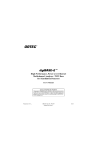
If connecting multiple 926s via the printer port, every
MCB in the system must be assigned a unique MCB
address. (You may find it useful to mark the front
panel of each instrument with its MCB address.)
Figures 3 and 4 show two printer-port systems with
the jumper settings for the various 926s.
3.1. LIVE-TIME MODE
The Model 926 has two different live-time correction
modes: Extended and Simple. The Extended mode
is the Gedcke-Hale correction mode which corrects
for losses caused by pileup in the shaping amplifier.
This is the default setting and is usually the correct
setting for energy spectroscopy systems. The
Simple Live-Time correction mode simply stops the
live-time clock when the BUSY signal is active, the
Model 926 detects that a pulse is arriving at its input,
or the 926 is busy digitizing data. The Simple LiveTime mode is appropriate only in very specialized
situations and is not the correct setting for most
users.
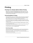
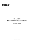
To change the live-time correction mode, remove
the right side plate of the Model 926 by removing the
four screws. Figure 2 shows the location of the livetime correction mode jumper. Place the jumper
across the lower two pins for Extended Live-Time
correction and across the upper two pins for Simple
Live-Time correction.
Once an address is established for each MCB in the
system, the hardware must be set to that address.
On the Model 926 the address is set with the rotary
switch highlighted in Fig. 2. To access this switch,
remove the right side plate. The switch should be
set to 1 less than the MCB address. For example if
the MCB address is 1, set the switch to 0.
3.3. MCB/PRN JUMPER FOR PRINTERPORT CONNECTIONS
The MCB/PRN jumper must be correctly set when
the printer-port interface is used.
To connect an MCB only — If the jumper is in the
MCB position, an MCB can be connected to the
PRINTER connector.
To connect a printer and MCB — If the jumper is
in the PRN position, a printer can be connected to
the PRINTER connector on the rear panel of the
Model 926.
3.2. MCB ADDRESS
The Model 926 can be installed in a system with
multiple ORTEC MCBs. However, to prevent
hardware conflicts when using older MCBs it might
be necessary for you to manually change the MCB
address for one or more instruments.
If connecting to your PC with a DPM-USB interface
converter, no MCB address change is needed; leave
the unit’s address at the factory default setting of 1.
If changing older 926s from the legacy DPM ribbon
cable interface to the DPM-USB converter, make
The jumper is set to MCB when the Model 926
leaves the factory. To change the MCB/PRN jumper,
remove the right side plate of the Model 926 by
removing the four screws. Figure 1 shows the
location of the jumper. Place the jumper across the
right two pins for PRN and across the left two pins
for MCB.
Figures 3 and 4 show how the MCB/PRN jumper
should be set for a single-MCB and a multi-MCB
system.
4
Fig. 2. Model 926 Address Switch and Jumpers.
Fig. 3. Single Model 926 Using Printer-Port Interface.
5
Fig. 4. Printer Port System with Four 926s.
6
3.4. PRINTER-PORT VS DUAL-PORT
MEMORY INTERFACE
You can purchase the Model 926 pre-set for use
with either the DPM-USB Dual-Port-Memory-to-USB
Interface Converter or the printer-port interface. The
DPM-USB converter requires that the Dual-PortMemory Interface option be installed. If your 926 is
configured for the Dual-Port Memory Interface and
you wish to convert to the printer-port interface, see
Section 3.4.1. If the unit is configured for the printerport interface and you wish to convert to the DualPort Memory Interface, see Section 3.4.2.
3.4.1. Installing the Printer-Port Interface
If the Dual-Port Memory Option has been installed in
the 926, the Printer Option must be reinstalled if a
printer or second MCB is to be connected to the
926. To install the Printer Option do the following:
1.
2.
3.
4.
5.
6.
7.
8.
Remove the right side plate by removing the
four screws which hold it in place.
Using a 3/16" nut driver, remove the two hex
nuts which hold the Dual-Port Memory (DPM)
connector to the rear panel.
Slide the connector out of the rear-panel slot.
Disconnect the DPM cable from the Model 926
board by pulling straight up on the header which
connects the DPM cable to the board.
Store the cable, hex nuts, and washers in a
safe place.
Carefully plug the Printer Option in to the row of
pins close to the rear panel (see Figure 4). The
connector is keyed for proper installation.
Slide the other end of the cable into the rear
panel of the 926. Secure the connector with two
screws.
Replace the side plate.
Figures 3 and 4 show wiring diagrams for several
printer port systems. The cables used are 25-pin
shielded male-female cables. The cable from the
computer to the first Model 926 should be no longer
than 10 feet (3 meters). Cables connecting
additional 926s should be no longer than 2 feet
(0.6 meters). These cables are available from
ORTEC by ordering Model 926-C-10 for a 10-foot
cable and Model 926-C-2 for a 2-foot cable. The
cable used to connect a Model 926 to a printer is a
standard printer cable which normally connects a
computer to a printer.
3.4.2. Installing the Dual-Port Memory
Interface
If your 926 is configured for the printer-port interface
and you wish to use the Dual-Port Memory interface
instead, two steps are necessary: the instrument
must be reconfigured and you must purchase either
the DPM-USB Dual-Port-Memory-to-USB Interface
Converter or the classic Dual-Port Memory Interface
ribbon cable from ORTEC.
To reconfigure the 926, you must install the DualPort Memory Option, which is included with each
926. It is a 37-pin ribbon cable with a 37-pin D
connector on one end and a 40-pin header on the
other end. To install the Dual-Port Memory Option,
do the following, referring to Fig. 5:
Fig. 5. Location of Option Connectors.
1.
2.
3.
4.
5.
6.
7.
8.
Remove the right side plate by removing the
four screws which hold it in place.
Remove the two Phillips screws that hold the
PRINTER panel in place.
Slide the PRINTER panel out of the rear-panel
slot.
Disconnect the PRINTER option from the
Model 926 board by pulling straight up on the
header which connects the ribbon cable to the
board.
Store the cable and screws in a safe place.
Carefully plug the Dual-Port Memory option
Slide the connector into the rear panel of the
926. Secure the connector with 3/16" hex nuts
and washers provided.
Replace the side plate.
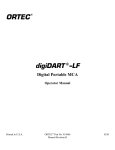
3.5. CABLING A SYSTEM
The standard cabling of a 926 in a HPGe detector
system is shown in Fig. 6.
7
Fig. 6. HPGe Cabling Diagram.
8
If the detector has a TRP preamplifier ("-PLUS"
model), all connections shown should be made. If
the preamplifier is a resistive-feedback preamplifier,
the INHIBIT OUTPUT does not exist, so the
connection to INHIBIT is not made. (INHIBIT is left
open.)
amplifiers have very little dc offset. Should offset
adjustment be necessary, turn the screwdriver
adjustment clockwise to move peaks in the
spectrum to the right and counterclockwise to move
them to the left.
3.8. ENABLING THE GATE INPUT
3.6. ADJUSTING THE LOWER-LEVEL
DISCRIMINATOR
The Lower-Level Discriminator (LLD) adjustment is
used to prevent small noise pulses from being
converted by the ADC. Converting the noise pulses,
causes the ADC to incur a large amount of dead
time, thereby preventing the ADC from converting
the actual pulses of interest. When the Model 926 is
shipped from the factory, the LLD setting is
approximately 75 mV, so no pulses smaller than
75 mV are converted or histogrammed. This setting
is adequate for most systems.
If the system has high noise or there is a very low
energy peak in the spectrum, it may be
advantageous to adjust the LLD setting. In the high
noise system, start collecting data and observe the
dead time on the screen along with the number of
counts arriving at the low end of the spectrum. With
a small screwdriver, turn the LLD adjustment on the
front panel clockwise, until the dead time drops or
the peaks due to noise at the low end of the
spectrum stop getting new counts. If there is a low
energy peak in the spectrum, it may be necessary to
lower the LLD setting to prevent the peak from being
rejected. Start data acquisition and observe the low
end of the spectrum while turning the LLD
adjustment on the front panel counterclockwise.
Continue the adjustment until the peak is in the
spectrum. Caution: Do not lower the adjustment
such that the dead time goes to 100%.
3.7. SETTING THE ZERO ADJUSTMENT
The Zero Adjustment is provided to add or subtract
a dc level from the input signal. The Zero
Adjustment is on the front panel of the Model 926.
Usually no zero adjustment is required or
recommended, since most modern spectroscopy
The Gate on the front panel operates in one of three
modes:
!
!
!
Off — The Gate Input does nothing.
Coincidence — For a pulse to be converted, the
Gate Input must be active (>2.5 V) when the
pulse reaches its peak and for 0.5 µs thereafter.
Anticoincidence — For a pulse to be converted,
the Gate Input must be inactive (<0.8 V) when the
pulse reaches its peak and for 0.5 µs thereafter.
When the Model 926 is shipped from the factory, the
Gate Input is set Off. To change the Gate Input
mode, a SET_GATE command must be sent to
the 926. This command can be sent within
MAESTRO-32 by creating an ASCII-text .JOB file.
Create a .JOB file as follows to set the gate to
Coincidence:
1.
2.
3.
4.
Go to the Services menu.
Select Job Control.
Select Edit File (takes you to Notepad).
Type:
SEND_MESSAGE “SET_GATE_COIN” 5
5.
6.
7.
Save as COIN.JOB then exit Notepad.
Refresh display by reentering Job Control.
Select COIN.JOB and click on OK.
To set gate to Anticoincidence or to disable the
GATE, replace COIN in Steps 4 and 5 with ANTI or
OFF. Refer to the MAESTRO User’s Manual for
more information on creating .JOB files. The Gate
Mode setting is stored in the 926’s memory, so the
command or .JOB file need only be executed once,
unless the battery fails.
9
4. MCA BASICS
value which is applied to the input. The Peak
Stretcher also has a Peak Detect output which
goes active when its output is greater than the
value at its input.
The first half of this section describes the circuitry
found on the Model 926 board (MCB) while the
second half describes the dead-time effects
encountered in an MCA.
4.1. MCB OPERATION
!
This section contains a very basic description of the
input circuitry and the chain of events that occurs in
the Model 926 when an input pulse arrives to be
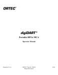
histogrammed. Figure 7 shows the basic block
diagram of the input section of the Model 926. First
a description of each block in the circuit:
!
!
!
!
Buffer — The buffer is provided to properly
match impedances between the input and the
Model 926 circuitry.
Linear Gate — The Linear Gate protects the
peak stretcher during conversion of an event.
When the Linear Gate is "open," its output is
identical to its input. When the Linear Gate is
"closed," its output is always zero.
Peak Stretcher — The peak stretcher operates
in one of two modes: Track or Hold. In Track
mode, the output of the peak stretcher is identical
to its input. In Hold mode, the peak stretcher acts
like a maximum function. It outputs the maximum
!
Analog-to-Digital Converter — The Analog-toDigital Converter (ADC) takes an analog signal
and converts it to a digital equivalent.
Zero-Level, Lower-Level, and Upper-Level
Discriminators — The discriminators provide 3
control signals which help control the conversion
process. The Zero-Level Discriminator (ZLD) is
active, when the input signal is greater than 1/2 of
the Lower-Level Discriminator setting. The
Lower-Level Discriminator (LLD) is active, when
the input signal is greater than the Lower-Level
Discriminator setting. The Upper-Level
Discriminator (ULD) is active when the input
signal is greater than the maximum possible ADC
output. The Lower-Level Discriminator settings is
set with a screwdriver adjustment on the front
panel.
ADC Control — This circuit accepts all of the
various status signals and provides the control
signals required to complete a conversion.
Fig. 7. Model 926 Input Block Diagram.
!
Microprocessor — The microprocessor accepts
the digital data and adds it to the spectrum.
Upon arrival of an input pulse, the sequence of
events is as follows:
!
!
ZLD goes active when the input reaches 1/2 of
the LLD setting.
When ZLD goes active, the peak stretcher is
switched to Hold mode.
10
!
!
When Peak Detect goes active, LLD, PUR,
GATE, and ULD are sampled. If any of these
signals rejects the pulse, then the Peak Stretcher
is returned to Track mode. If the pulse is
accepted, the Linear Gate is closed and the ADC
is given the convert signal.
obtain the overall system dead time. For accurate
live time, the PUR and BUSY signals must be
connected from the amplifier to the 926.
When the ADC is finished converting, the data is
transferred to the microprocessor for
histogramming, the Linear Gate is opened, and
the Peak Stretcher is returned to Track mode.
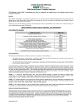
4.2. DEAD TIME IN MCA AND AMPLIFIER
When a detector, preamplifier, spectroscopy
amplifier, and MCA are combined to form a
spectroscopy system, the dead times of the
amplifier and the MCA are in series (see Fig. 8). The
combination of the amplifier extending dead time
followed by the MCA non-extending dead time TM
yields a throughput described by:
The rate of events arriving at the detector is ri, and
ro is the rate of analyzed events in the MCA
spectrum. TW is the width of the amplifier pulse at
the noise discriminator threshold (Figure 7). TP is the
time from the start of the amplifier pulse to the point
at which the MCA detects peak amplitude and
closes the linear gate. U[TM!(TW !TP)] is a unit step
function that changes from 0 to 1 when TM is greater
then (TW !TP). TM is the conversion time of the ADC
and includes the time required to transfer the data to
the subsequent memory.
The 926 Extended Live Timer utilizes the GedckeHale method to correct for the dead-time losses
implied by the equation above. When the counts in
a full-energy peak are divided by the live time, the
resulting counting rate is an accurate estimate of the
true counting rate for that gamma-ray energy at the
detector output. The Gedcke-Hale method uses the
amplifier analog output, BUSY and PUR (Pile-UpReject) signals. The amplifier dead time is combined
with the ADC conversion and readout dead time to
Fig. 8. The Sources of Dead Time with an Amplifier and
MCA.
The Gedcke-Hale live-time clock works as follow:
!
!
!
Either the leading edge of the amplifier BUSY
signal or the crossing of the ADC Lower-Level
Discriminator (LLD) by the ADC input causes the
live-time clock to start counting backwards.
The live-time clock is turned off by the ADC peak
detect or by the amplifier PUR signal.
The live-time clock resumes counting forward
after all of the following signal conditions are
satisfied:
— The ADC conversion and readout is
complete.
— The ADC input has returned below the LLD
threshold.
— The PUR and BUSY signals have returned
to the inactive state.
Turning off the live-time clock compensates for the
probability of losing a second pulse during the
processing of the first pulse. Subtracting live time
compensates for the probability of losing two pulses
when the second pulse distorts the amplitude of the
first pulse.
11
5. TROUBLESHOOTING GUIDE
This section of the manual contains some
troubleshooting hints to help when something goes
wrong. Below are listed several common problems
and possible solutions:
5.1. DUAL-PORT MEMORY DOES
NOT EXIST
!
Carefully review the instructions in Section 3.2
and ensure that the MCB address has been
properly set.
5.2. BATTERY BACKUP FAILS
used is a lithium battery with a nominal voltage of
3 V.
To replace battery: Remove the right-side plate.
Locate battery on the top right corner of the 926
(see Figure 1). Remove the old battery from the
holder and slide a new one in. It may be necessary
to bend the battery holder down after removing the
old battery to get good contact with the new battery.
BATTERY SPECIFICATION:
P/N 739480.
Lithium coin cell,
The memory in the Model 926 has battery backup to
maintain data when power is turned off. The battery
APPENDIX A. FIRMWARE COMMANDS AND RESPONSES
Software communication with the DSPEC Pro takes
place through the CONNECTIONS-32 software layer.
CONNECTIONS-32 is used by all ORTEC software and
can be accessed for other software development
with our CONNECTIONS-32 Programmer’s Toolkit with
Microsoft ActiveX® Controls (A11-B32).
A.1. CONNECTIONS-32
In CONNECTIONS-32, the communication consists of
sending command records to the MCB API and
receiving response records from the MCB API. Both
command and response records consist of a
sequence of printable ASCII characters followed by
an ASCII carriage return. The single exception to
this rule is the “#B” response record for the WRITE
command, which contains binary integer numbers.
All commands eventually respond with a percent
response record (so named because the response
begins with an ASCII percent sign “%”) which
signifies the completion of the command. SHOW
and STEP commands respond with a dollar
response record (which begins with an ASCII dollar
sign “$”) followed by a percent response record. The
WRITE command can respond with multiple pound
sign records (which begin with an ASCII pound sign
“#”) but eventually completes by sending a percent
response record. All other commands result in a
single percent response record upon completion.
A.2. COMMAND RECORDS
The Model 926 commands consist of a command
header, which may be followed by numeric
parameter values. The header consists of a verb or
a verb and noun separated by an underscore or a
verb, noun, and modifier, each separated by
underscores. The verbs, nouns, and modifiers in the
command header are mnemonic words such as the
verb ENABLE or the noun OVERFLOW that relate
to the function performed by the MCB when it
executes the command. The first four letters of
any word will always be enough to uniquely
identify the word when composing commands for an
MCB. For example, the command
ENABLE_OVERFLO W _PRESET can be
abbreviated to ENAB_OVER_PRES.
Numeric parameters are unsigned integer numbers
that follow the command header separated by one
or more spaces. Specific commands require up to
three parameters, separated by commas, which
specify numeric quantities related to the operation of
the MCB, such as live time or conversion gain. The
command SET_WINDOW 0,8192 has two
parameters, 0 and 8192, which set the window-ofinterest to start at channel 0 and continue for 8192
channels.
Some parameters listed in the command dictionary
are considered optional and are distinguished from
mandatory parameters by being surrounded by
brackets in the command prototype line (e.g.,
12
SET_WINDOW [start,length]). Commands that
have optional parameters may be sent to the MCB
without the optional parameters, in which case the
behavior will be changed as explained in the
command description.
An optional checksum may be added to the end of
any command sent to an MCB. The checksum is a
1-byte unsigned integer sum of all of the characters
in a command, treated as unsigned integers, up to
and including the comma or space(s) that separates
the checksum from the command. The checksum
simply appears as an extra parameter added to the
end of the command parameter list. For commands
that do not normally have parameters, the
checksum appears as the only parameter separated
from the header by one or more spaces. All optional
parameters must be included in a command if a
checksum is to be provided so that the checksum is
not mistaken by the MCB as a parameter. For
example, the SET_WINDOW command must
include the two optional parameters, start and
length, if the checksum is
SET_WINDOW 0,8192,159).
provided
A.3. PERCENT RESPONSE RECORDS
The 926 MCBs respond to all commands with a
percent response record that signifies the
completion of the command. Percent response
records contain two error code numbers and a
1-byte checksum as follows:
%aaabbbccc<CR>
where % represents the ASCII % character, aaa
represents the macro error code, bbb represents
the micro error code, ccc represents the checksum,
and <CR> represents the ASCII carriage return
character signifying the end of the record. The
macro error code represents the general class of
error with 0 meaning no error, and the micro error
code represents the sub-class of error with 0
meaning no error. The following table lists all
percent responses for a Model 926:
Unconditional Success:
%000000069
No Errors Detected.
START/STOP Warnings:
%000005074
MCB already started or stopped.
%000006075
Preset already exceeded.
%001000070
All power-up selftests passed.
%003000072
Battery backed-up data lost
%005002076
ROM failed selftest
%004002075
ROM failed selftest
%004008081
Processor memory failed selftest
%004016080
Dual-Port memory failed selftest
%004010074
ROM and Processor memory failed selftest
%004018082
ROM and Dual-Port memory failed selftest
%004024079
Processor and Dual-Port memory failed
%004026081
ROM, processor memory, and Dual-Port failed
%129001082
Invalid verb in command
%129002083
Invalid noun in command
%129003084
Invalid verb and noun in command
%129004085
Invalid modifier in command
%129005086
Invalid verb and modifier in command
%129006087
Invalid noun and modifier in command
%129007088
Invalid verb, noun and modifier in command
Power-Up Alert:
TEST Command Results:
Command Syntax Errors:
(e.g.,
13
Communication Errors:
Execution Errors:
%129132087
Invalid command (verb, noun, and modifier valid, but not
together)
%130128084
Incorrect checksum (only if checksum provided)
%130129085
Command record too long
%131128085
Invalid 1st parameter
%131129086
Invalid 2nd parameter
%131130078
Invalid 3rd parameter
%131132080
Invalid number of parameters
%131135083
Illegal command while acquisition is in progress
%131136084
Illegal command in current mode of operation
A.4. DOLLAR RESPONSE RECORDS
SHOW commands respond with a single dollar
response record followed immediately by a percent
response record. All valid dollar response records
for each command are listed in the command
dictionary.
The following table lists the general form of each
dollar response record for a 926 MCB. In this table
lowercase letters represent numeric values. The
letters "ccc" always represent an 8-bit unsigned
checksum of all characters on the record up to but
not including the checksum characters, and <CR>
represents the ASCII carriage return character.
Response
Description
$Axxxccc
xxx is an 8-bit unsigned number
$Cxxxxxccc
xxxxxx is a 16-bit unsigned number
$Dxxxxxyyyyyccc
xxxxx and yyyyy are 16-bit unsigned numbers
$Exxxxxccc
xxxxx is a 16-bit alarm mask
$Fsssss...
ssss... is a variable length ASCII character sequence (No checksum is sent with
this record)
$Gxxxxxxxxxxccc
xxxxxxxxxx is a 32-bit number
$IT
True response to a SHOW command (no checksum)
$IF
False response to a SHOW command (no checksum)
$Jxxxxxyyyyy...ccc
Response to SHOW_CONFIG command.
$Mxxxxxxxxxx...ccc
Response to SHOW_STATUS command.
$Nxxxyyyzzzccc
xxx,yyy and zzz are 8-bit unsigned numbers.
A.5. COMMAND CATALOG
This section lists each Model 926 command with a
description of its operation. The descriptions include
a list of any unusual responses that may result. As
described in previous sections, the usual response
from a command is a %000000069<CR> response,
which represents a macro error code of 0 and a
micro error code of 0 (no errors).
All execution error responses, if any, are listed for
each command. Though syntax and communication
error responses may result from any command, in
practice, these error responses rarely occur on
systems with reliable communication hardware
running debugged software. Refer to the section on
Percent Response Records in this Appendix for
information about error responses.
14
In the following catalog the commands are listed in
alphabetical order, each starting with a command
prototype line. Uppercase letters, numeric digits,
blank space, and special symbols such as the
underscore "_" and comma "," in the prototype line
are literal text to be sent to the MCB exactly as it
appears. Lowercase letters in the prototype line
represent numeric values as described in the
accompanying text and should not be sent literally to
the
MCB but should be replaced by an appropriate
numeric value. Items in the command prototype that
are surrounded by brackets "[...]" are optional items
and are not always required.
In this section the term <CR> represents the ASCII
carriage return character, decimal value 13, and the
character "_" represents the ASCII underscore
character, decimal value 95.
CLEAR
The channels of spectral data in the window-of-interest (see SET_WINDOW command) are set to
zero. The live-time and true-time counters are also set to zero. This command is equivalent to the
combination of CLEAR_COUNTERS and CLEAR_DATA commands.
CLEAR_ALL
This command is equivalent to the combination of CLEAR_COUNTERS, CLEAR_DATA,
CLEAR_PRESETS, and CLEAR_ROI commands.
Execution Errors:
%131135083<CR> The command was attempted while spectrum acquisition was in progress.
No action was taken.
CLEAR_COUNTERS
The live-time and true-time counters are set to zero.
CLEAR_DATA
The channels of spectral data in the window-of-interest (see SET_WINDOW command). The ROI
flags are not changed, nor are the presets changed.
CLEAR_PRESETS
The live time, true time, ROI integral, ROI peak, and overflow presets are all set to zero (disabled).
Execution Errors:
%131135083
The command was attempted while spectrum acquisition was in progress.
No action was taken.
CLEAR_ROI
The region-of-interest flags for the channels in the window-of-interest (see SET_WINDOW
command) are cleared.
Execution Errors:
%131135083
The command was attempted while spectrum acquisition was in progress.
No action was taken.
DISABLE_ALARM
Ends the transmission of alarm responses when acquisition stops. See also ENABLE_ALARM
and SHOW_ALARM.
DISABLE_OVERFLOW_PRESET
Disables the overflow preset. Channels that receive a count when they contain 2147483647
counts, the maximum number of counts, will roll over to zero counts if the overflow preset is
disabled. See also ENABLE_OVERFLOW_PRESET and SHOW_OVERFLOW_PRESET.
15
ENABLE_ALARM
Begins the transmission of alarm responses, $E records, when an input stops counting. A $E
response record will be transmitted only when no host commands are being processed (after a %
response from a previous command and before another command is sent). See also
DISABLE_ALARM and SHOW_ALARM.
ENABLE_OVERFLOW_PRESET
Enables the overflow preset. Channels that receive a count when they contain 2147483647
counts, the maximum number of counts, will stop the acquisition for that channel's device if the
overflow preset is disabled. The channel that caused the preset to complete will contain
214783647 counts. An alarm response record will be sent to the host if alarms are enabled (see
ENABLE_ALARM command). See also DISABLE_OVERFLOW_PRESET and
SHOW_OVERFLOW_PRESET commands.
INITIALIZE
Resets the Model 926 hardware and software as though the following commands had been
issued:
STOP
SET_WINDOW 0,8192
SET_GATE_OFF
TEST 1
CLEAR_ALL
SET_GAIN_CONVERSION 0
Execution Errors:
The INITIALIZE command simulates a power-down/power-up cycle for the MCB after a simulated
loss of battery backed-up memory. Thus the % response record is the response from the PowerUp Alert.
%003000072<CR>
MCB Power-up occurred/Memory lost/No selftest errors
(Normal Response for INITIALIZE command)
%007002078<CR>
All of above but selftest failed/ROM failed.
RESET
Resets the 926 to the state just after power is applied. This command responds with a %
response that indicates power-up just occurred.
SET_DATA count
Sets all channels of spectral data in the window-of-interest (see SET_WINDOW command) for the
currently selected device (see SET_DEVICE command) to the specified count. ROI flags are not
affected.
SET_GAIN_CONVERSION chans
Sets the conversion gain. The conversion gain defines the number of channels within the device
that will used for spectral data. This has the effect of altering the resolution of the ADC from 13/11
bits (conversion gain = 8192/2048) to 9 bits (conversion gain = 512) for the device.
Legal Commands:
SET_GAIN_CONVERSION 0<CR>
Conversion gain set to default (8192)
SET_GAIN_CONVERSION 512<CR>
Conversion gain set to 512 channels
SET_GAIN_CONVERSION 1024<CR> Conversion gain set to 1024 channels
SET_GAIN_CONVERSION 2048<CR> Conversion gain set to 2048 channels
SET_GAIN_CONVERSION 4096<CR> Conversion gain set to 4096 channels
SET_GAIN_CONVERSION 8192<CR> Conversion gain set to 8192 channels
SET_GATE_ANTICOINCIDENT
Causes the MCB to expect the ADC gate input signal in anticoincident mode. See the section on
the ADC gate input for more information. See also SET_GATE_OFF, SET_GATE_COINCIDENT,
and SHOW_GATE.
16
SET_GATE_COINCIDENT
Causes the MCB to expect the ADC gate input signal in coincident mode. See the section on the
ADC gate input for more information. See also SET_GATE_OFF,
SET_GATE_ANTICOINCIDENT, and SHOW_GATE.
SET_GATE_OFF
Causes the MCB to ignore the state of the ADC gate input signal. See the section on the ADC
gate input for more information. See also SET_GATE_COINCIDENT,
SET_GATE_ANTICOINCIDENT, and SHOW_GATE.
SET_INTEGRAL_PRESET count
Sets the ROI integral preset to the specified count. During data acquisition when the sum of the
counts contained in the channels of a device that have the ROI flag set reaches the integral preset
count, the preset is complete and the acquisition is stopped. The actual number of counts in the
ROI integral may exceed the preset value by up to 512 counts due to the pipelined architecture of
the 926. Setting an integral preset to 0 counts disables the preset. The integral preset may be set
to from 0 (disabled) to 4294967295 counts. See also CLEAR_PRESETS and
SHOW_INTEGRAL_PRESET.
Execution Errors:
%131135083<CR> The command was attempted while spectrum acquisition was in progress.
No action was taken.
SET_LIVE_PRESET ticks
Sets the live-time preset to the specified number of ticks. During data acquisition when the livetime counter reaches the preset number of ticks, the preset is complete and the acquisition is
stopped. Setting a live-time preset to 0 ticks disables the preset. See also CLEAR_PRESETS and
SHOW_LIVE_PRESET.
Execution Errors:
%131135083<CR> The command was attempted while spectrum acquisition was in progress.
No action was taken.
SET_PEAK_PRESET count
Sets the ROI peak preset to the specified count. During data acquisition when the contents of any
channel of a device that has the ROI flag set reaches the peak preset count, the preset is
complete and the acquisition is stopped. The actual number of counts in the ROI peak may
exceed the preset value by a small number of counts due to the pipelined architecture of the 926.
Setting a peak preset to 0 counts disables the preset. The peak preset may be set to from 0
(disabled) to 2147483647 counts. See also CLEAR_PRESETS and SHOW_PEAK_PRESET.
Execution Errors:
%131135083<CR> The command was attempted while spectrum acquisition was in progress.
No action was taken.
SET_ROI start_chan,number_of_chans
Sets the ROI flags for the specified channels. This command can be used multiple times to set
ROI flags without affecting previously set flags. ROI flags specify channels within a device that are
considered for ROI integral and ROI peak presets.
SET_TRUE_PRESET ticks
Sets the true-time preset to the specified number of ticks. During data acquisition when the truetime counter reaches the preset number of ticks, the preset is complete and the acquisition is
stopped. Setting a true-time preset to 0 ticks disables the preset. See also CLEAR_PRESETS and
SHOW_TRUE_PRESET.
Execution Errors:
%131135083<CR> The command was attempted while spectrum acquisition was in progress.
No action was taken.
17
SET_WINDOW [start, length]
Sets the window-of-interest to the specified start channel and number of channels. The channels
of spectral data in the window-of-interest are affected by commands such as CLEAR and
SET_DATA. If neither start or length is provided, the window is set to the maximum size allowed
by the conversion gain specified for the currently selected device. The window-of-interest is
always set to the maximum size after a SET_DEVICE command or a SET_SEGMENT command.
Execution Errors:
%131128085<CR> The start channel was too high for the conversion gain.
%131129086<CR> The length specified one or more channels that were too high for the
currently selected device's conversion gain.
%131132080<CR> The start channel was specified without a length. If one value is given the
other must be also given.
SHOW_ACTIVE
Returns a 1 if the ADC is active, acquiring spectral data, or 0 if it is not active.
Responses:
$C00000087<CR> The ADC is not active.
$C00001088<CR> The ADC is active.
SHOW_ALARM
Returns a record that indicated whether the alarm responses are enabled or disabled.
Responses:
$IT<CR>
Alarms are enabled.
$IF<CR>
Alarms are disabled.
SHOW_CONFIGURATION
Returns a record that indicates the hardware configuration of the MCB. The record contains
information about the number of segments in an MCB device (always one for the 926), and the
current conversion gain for each segment. The record is organized as follows:
$J0819200001aaaaa00000" 65 zeros here for total of 75 zeros "00000ccc for 8K
$J0204800001aaaaa00000" 65 zeros here for total of 75 zeros "00000ccc for 2K
Where aaaaa represents the conversion gain for the one and only segment in the currently
selected device, and ccc represents the record checksum. See the section on response records
in this appendix for more information about response records and checksums.
SHOW_GAIN_CONVERSION
This command returns the conversion gain.
Responses:
$C00512095<CR> Conversion gain reported as 512 channels
$C01024094<CR> Conversion gain reported as 1024 channels
$C02048101<CR> Conversion gain reported as 2048 channels
$C04096106<CR> Conversion gain reported as 4096 channels (8K only)
$C08192107<CR> Conversion gain reported as 8192 channels (8K only)
SHOW_GATE
Reports the current mode of operation of the ADC gate input. See also SET_GATE_OFF,
SET_GATE_COINCIDENT, and SET_GATE_ANTICOINCIDENT.
Responses:
$FOFF<CR>
Reports the ADC gate is off or ignored.
$FCOI<CR>
Reports the ADC gate is in coincident mode.
$FANT<CR>
Reports the ADC gate is in anticoincident mode.
18
SHOW_INTEGRAL [start_chan,number_of_chans]
Reports the sum of the specified group of spectral data channels. If start_chan and
number_of_chans is not provided, SHOW_INTEGRAL reports the sum of all channels that have
their ROI flag set.
Responses:
$G0000000000075<CR>
Integral reported as 0
...
...
$G4294967294131<CR>
Integral reported as 4294967294
$G4294967295132<CR>
Integral reported as greater than or equal to 4294967295
(maximum reportable value)
SHOW_INTEGRAL_PRESET
Reports the current ROI integral preset value. See SET_INTEGRAL_PRESET for more
information about the ROI integral preset. See also SHOW_INTEGRAL.
Responses:
$G0000000000075<CR>
Integral preset reported as 0
...
...
$G4294967295132<CR>
Integral reported as 4294967295
SHOW_LIVE
Reports the contents of the live-time counter in units of 20 milliseconds (50 ticks per second). See
also CLEAR_COUNTERS and SET_LIVE.
Responses:
$G0000000000075<CR>
Live time reported as 0 ticks
$G0000000001076<CR>
Live time reported as 1 tick (20 milliseconds)
...
...
$G4294967295132<CR>
Live time reported as 4294967295 ticks (over 23000 days)
SHOW_LIVE_PRESET
Reports the current live-time preset in units of 20 milliseconds (50 ticks per second). See also
CLEAR_PRESETS and SET_LIVE_PRESET.
Responses:
$G0000000000075<CR>
Live-time preset reported as disabled
$G0000000001076<CR>
Live-time preset reported as 1 tick
...
...
$G4294967295132<CR>
Live-time preset reported as 4294967295 ticks
SHOW_MODE
This command is for compatibility with Model 918 systems. It always reports that the 926 operates
in pulse-height analysis mode.
Responses:
$FPHA<CR>
19
SHOW_NEXT
Used in conjunction with the SHOW_ROI command, SHOW_NEXT reports the next continuous
group of channels that have the ROI flag set. The response is of the form:
$Dsssssnnnnnccc<CR> where sssss represents an integer number that is the number of the
first channel of the "next" group of channels that all have their ROI bit set, and nnnnn represents
an integer number that is the number of channels in the group. If no more channels have their ROI
bit set, SHOW_NEXT returns a first channel of 0 and a number of channels of 0. The SHOW_ROI
command is used to report the "first" group of channels that all have their ROI bit set.
Example Responses:
$D0100000050078<CR>
Next ROI group starts at chan 1000 and is 50 chans
long.
$D0215000150086<CR>
Next ROI group starts at chan 2150 and is 150 chans
long.
$D0000000000072<CR>
No other ROI groups to report
SHOW_OVERFLOW_PRESET
Reports the state of the overflow preset.
Responses:
$IT<CR>
Overflow preset enabled
$IF<CR>
Overflow preset disabled
SHOW_PEAK
This command returns the contents of the ROI channel with the largest number of counts. An ROI
channel is a channel that has the ROI flag set. The maximum possible value is 2147483647,
which is the maximum number of counts that can be stored in a 31-bit channel.
Responses:
$G0000000000075<CR>
Maximum count in an ROI channel is zero or no ROI
channels were found.
$G0000000001076<CR>
Maximum count in an ROI channel is 1.
...
...
$G2147483646120<CR>
Maximum count in an ROI channel is 2147483646.
$G2147483647121<CR>
Maximum count in an ROI channel is 2147483647.
SHOW_PEAK_CHANNEL
This command returns the number of the ROI channel with the largest number of counts. An ROI
channel is a channel that has the ROI flag set. The lowest number ROI channel with the largest
count is reported if more that one channel contains the largest number of counts. Channel 16383
is the highest numbered channel in any device.
Responses:
$C00000087<CR>
Maximum count was found in channel 0 or no ROI
channels were found.
$C00001088<CR>
Maximum count was found in channel 1.
...
...
$C08190105<CR>
Maximum count was found in channel 8190.
$C08191106<CR>
Maximum count was found in channel 8191.
20
SHOW_PEAK_PRESET
Reports the value of the ROI peak preset. See SET_PEAK_PRESET for information about the
ROI peak preset.
Responses:
$G0000000000075<CR>
Peak preset disabled
$G0000000001076<CR>
Peak preset set to 1 count
...
...
$G2147483646120<CR>
Peak preset set to 2147483646 counts
$G2147483647121<CR>
Peak preset set to 2147483647 counts
SHOW_ROI
Used in conjunction with the SHOW_NEXT command, SHOW_ROI reports the first continuous
group of channels that have the ROI flag set. The response is of the form:
$Dsssssnnnnnccc<CR> where sssss represents an integer number that is the number of the
first channel of the "first" group of channels that all have their ROI bit set, and nnnnn represents
an integer number that is the number of channels in the group. The SHOW_NEXT command is
used to report the "next" group of channels that all have their ROI bit set.
Responses:
$D0100000050078<CR>
First ROI group starts at chan 1000 and is 50 chans
long.
$D0215000150086<CR>
First ROI group starts at chan 2150 and is 150 chans
long.
$D0000000000072<CR>
No ROI groups to report
SHOW_TRUE
Reports the contents of the true-time counter in units of 20 milliseconds (50 ticks per second). See
also CLEAR_COUNTERS and SET_TRUE.
Responses:
$G0000000000075<CR>
True time reported as 0 ticks
$G0000000001076<CR>
True time reported as 1 tick (20 milliseconds)
...
...
$G4294967295132<CR>
True time reported as 4294967295 ticks (over 23000
days)
SHOW_TRUE_PRESET
Reports the current true-time preset in units of 20 milliseconds (50 ticks per second). See also
CLEAR_PRESETS and SET_TRUE_PRESET.
Responses:
$G0000000000075<CR>
True-time preset reported as disabled
$G0000000001076<CR>
True-time preset reported as 1 tick
...
...
$G4294967295132<CR>
True-time preset reported as 4294967295 ticks
SHOW_VERSION
Reports the firmware version number in the form: Fmmmm-vvv<CR>
where mmmm is a 4-character model designator and vvv is a 3-character version designator.
Example Responses:
$F0926-001<CR>
Model 926 firmware version 1 reported
21
SHOW_WINDOW
Reports the start channel and number of channels that are in the window of interest for the
currently selected device in the form: $Dxxxxxyyyyyccc<CR> where xxxxx is the start channel
(0 through 8191) and yyyyy is the number of channels (1 through 8192). See SET_WINDOW for
more information about the window-of-interest.
Example Responses:
$D0000008192092<CR>
Window of interest reported as starting at channel 0 and
continuing for 8192 channels.
START [seg-mask]
Starts the acquisition of spectral data. The optional segment mask is provided for compatibility
with other MCBs and may be any value from 0 to 65535 but is ignored by the Model 926.
Execution Warnings:
%000005074<CR>
The acquisition is already started (no changes made).
%000006075<CR>
A preset was exceeded (acquisition was not started).
STOP [seg-mask]
Stops the acquisition of spectral data. The optional segment mask is provided for compatibility
with other MCBs and may be any value from 0 to 65535 but is ignored by the Model 926.
Execution Warnings:
%000005074
Acquisition already stopped (no changes made
TEST mask
Performs any combination of the internal selftests where mask represents a 16-bit integer with
each bit set specifying a test as follows:
Bit 0 (LSB):
ROM checksum test (nondestructive)
Bit 1:
Spectral data memory test (destroys spectral data)
Bit 2:
Processor memory test (destroys spectral data)
Bit 3:
RESERVED
Bit 4:
RESERVED
Bit 5:
Mailbox memory test (may cause mailbox comm error)
Execution Errors:
%004002075<CR>
ROM failed test
%004008081<CR>
Processor Memory failed test
%004016080<CR>
Spectral Data Memory or Mailbox Memory failed test
The actual response record may be a combination of any of the above records depending on the
selftests performed. For example:
%004010074<CR>
Processor Memory and ROM1 both failed test
APPENDIX B. GLOSSARY
ACQUISITION
The process of collecting data from a detector and storing the data in memory.
ALARM RESPONSE RECORD
The response record that is sent to the host computer when one or more devices are stopped.
ASCII
American Standard Code for Information Interchange. The ASCII code is defined by ANSI (American
National Standards Institute) Standard X3.4 - 1977. This standard describes the representation of characters
as 8-bit binary numbers. This representation for characters is used by most mini and personal computers.
22
CHECKSUM
The sum of bytes in a record used to detect when communication errors occur.
CLOCK
A component of a device that keeps track of some form of time. 926 MCBs have live-time and true-time
clocks.
COUNTER
Another name for a 926 clock (live-time or true-time).
DEAD TIME
The time that data acquisition is active but the MCB cannot process detector pulses (is dead). Dead time is
equal to the true time minus the live time for a device.
DEVICE
The entity within an MCB that collects and stores spectral data. A device corresponds to the MCB's inputs.
Model 919 MCBs have 4 inputs and thus 4 devices, while 926 MCBs have only 1 input and thus 1 device.
A device can be started, stopped, cleared, and selected.
HOST
The computer that sends commands to an MCB and receives responses from the MCB.
LIVE TIME
The time that data acquisition is active and the MCB is capable of processing detector pulses (is live). Live
time is equal to the true time minus the dead time for a device.
PRESET
A limit set for a clock or region-of-interest count that if exceeded during an acquisition will cause the
acquisition to stop. 926 MCBs have live time, true time, ROI integral, ROI peak, and overflow presets for
each device in the MCB.
PROGRAM MEMORY
The ROM memory inside the 926 MCB that contains the microprocessor instructions and fixed data that
control the operation of the MCB.
RAM
Random Access Memory.
RECORD
A sequence of related bytes. 926 command, percent, and dollar records are composed of printable ASCII
characters and end with an ASCII carriage return.
ROI CHANNEL
A channel that has the ROI flag set.
ROI FLAG
A set of internal MCB flags (one for each channel) which, when set, identifies the channel as being part of
the region-of-interest. All channels in a device that have the ROI flag set are considered when ROI integral
or ROI peak presets are evaluated.
ROM
Read-Only Memory.
23
SCRATCHPAD MEMORY
The RAM memory inside the 926 MCB that is used for various overhead operations. The scratchpad memory
is all the memory that is not used for storage of spectral data or mailbox communications.
SEGMENT
A subdivision of a device. Segments are not implemented on 926 MCBs and are referenced only for
compatibility with other MCBs.
SELFTEST
A test of internal MCB components initiated by the TEST command or MCB power-up..
TICK
The minimum unit of time associated with a clock such as the real-time or live-time clocks — a clock tick.
TRUE (REAL) TIME
The actual time that data acquisition is active regardless of the MCB’s ability to process detector pulses. True
time is also known as real time.
WINDOW-OF-INTEREST
The continuous group of channels affected by commands like CLEAR and SET_DATA. The window-ofinterest is set by the SET_WINDOW command, as well as by the SET_DEVICE and SET_SEGMENT
commands.
24
INDEX
ADC gate . . . . . . . . . . . . . . . . . . . . . . . . . . . . . . . . . . . . . . . . . . . . . . . . . . . . . . . . . . . . . . . . . . . . . . . . 2, 16, 17
ADC LLD . . . . . . . . . . . . . . . . . . . . . . . . . . . . . . . . . . . . . . . . . . . . . . . . . . . . . . . . . . . . . . . . . . . . . . . . . . . . . . 1
ADC Zero . . . . . . . . . . . . . . . . . . . . . . . . . . . . . . . . . . . . . . . . . . . . . . . . . . . . . . . . . . . . . . . . . . . . . . . . . . . . . 1
Alarm responses . . . . . . . . . . . . . . . . . . . . . . . . . . . . . . . . . . . . . . . . . . . . . . . . . . . . . . . . . . . . . . . . . . . . 15, 17
Analog-to-Digital Converter . . . . . . . . . . . . . . . . . . . . . . . . . . . . . . . . . . . . . . . . . . . . . . . . . . . . . . . . . . . . . . . . 9
Battery . . . . . . . . . . . . . . . . . . . . . . . . . . . . . . . . . . . . . . . . . . . . . . . . . . . . . . . . . . . . . . . . . . . . . . . . . . . . . . . 11
BUSY . . . . . . . . . . . . . . . . . . . . . . . . . . . . . . . . . . . . . . . . . . . . . . . . . . . . . . . . . . . . . . . . . . . . . . . . . . . . . . . . 2
Conversion gain . . . . . . . . . . . . . . . . . . . . . . . . . . . . . . . . . . . . . . . . . . . . . . . . . . . . . . . . . . . . . . . . . . . . . . . . 15
Data Memory . . . . . . . . . . . . . . . . . . . . . . . . . . . . . . . . . . . . . . . . . . . . . . . . . . . . . . . . . . . . . . . . . . . . . . . 11, 13
Deadtime . . . . . . . . . . . . . . . . . . . . . . . . . . . . . . . . . . . . . . . . . . . . . . . . . . . . . . . . . . . . . . . . . . . . . . . . . . . . . . 1
Differential Nonlinearity . . . . . . . . . . . . . . . . . . . . . . . . . . . . . . . . . . . . . . . . . . . . . . . . . . . . . . . . . . . . . . . . . . . 1
DPM-USB interface . . . . . . . . . . . . . . . . . . . . . . . . . . . . . . . . . . . . . . . . . . . . . . . . . . . . . . . . . . . . . . . . . . . 1-3, 6
Firmware version . . . . . . . . . . . . . . . . . . . . . . . . . . . . . . . . . . . . . . . . . . . . . . . . . . . . . . . . . . . . . . . . . . . . . . . 20
Gate . . . . . . . . . . . . . . . . . . . . . . . . . . . . . . . . . . . . . . . . . . . . . . . . . . . . . . . . . . . . . . . . . . . . . . . . . . . . . . . . . 8
Gedcke-Hale . . . . . . . . . . . . . . . . . . . . . . . . . . . . . . . . . . . . . . . . . . . . . . . . . . . . . . . . . . . . . . . . . . . . . . . . 3, 10
Integral . . . . . . . . . . . . . . . . . . . . . . . . . . . . . . . . . . . . . . . . . . . . . . . . . . . . . . . . . . . . . . . . . . . . . . . . . . . . . . 18
Integral Nonlinearity . . . . . . . . . . . . . . . . . . . . . . . . . . . . . . . . . . . . . . . . . . . . . . . . . . . . . . . . . . . . . . . . . . . . . . 1
Integral preset . . . . . . . . . . . . . . . . . . . . . . . . . . . . . . . . . . . . . . . . . . . . . . . . . . . . . . . . . . . . . . . . . . . . . . . . . 18
Linear Gate . . . . . . . . . . . . . . . . . . . . . . . . . . . . . . . . . . . . . . . . . . . . . . . . . . . . . . . . . . . . . . . . . . . . . . . . . . . . 9
Livetime . . . . . . . . . . . . . . . . . . . . . . . . . . . . . . . . . . . . . . . . . . . . . . . . . . . . . . . . . . . . . . . . . . . . . . . . . . . . . . 14
Lower-Level Discriminator . . . . . . . . . . . . . . . . . . . . . . . . . . . . . . . . . . . . . . . . . . . . . . . . . . . . . . . . . . . . . . . . . 8
Overflow preset . . . . . . . . . . . . . . . . . . . . . . . . . . . . . . . . . . . . . . . . . . . . . . . . . . . . . . . . . . . . . . . . . . . . . 14, 19
PEAK . . . . . . . . . . . . . . . . . . . . . . . . . . . . . . . . . . . . . . . . . . . . . . . . . . . . . . . . . . . . . . . . . . . . . . . . . . . . . . . 19
Peak Channel . . . . . . . . . . . . . . . . . . . . . . . . . . . . . . . . . . . . . . . . . . . . . . . . . . . . . . . . . . . . . . . . . . . . . . . . . 19
Peak Stretcher . . . . . . . . . . . . . . . . . . . . . . . . . . . . . . . . . . . . . . . . . . . . . . . . . . . . . . . . . . . . . . . . . . . . . . . . . . 9
POWER . . . . . . . . . . . . . . . . . . . . . . . . . . . . . . . . . . . . . . . . . . . . . . . . . . . . . . . . . . . . . . . . . . . . . . . . . . . . . . 2
Presets . . . . . . . . . . . . . . . . . . . . . . . . . . . . . . . . . . . . . . . . . . . . . . . . . . . . . . . . . . . . . . . . . . . . . . . . . . . . . . . 1
Printer-port interface . . . . . . . . . . . . . . . . . . . . . . . . . . . . . . . . . . . . . . . . . . . . . . . . . . . . . . . . . . . . . . . . . . 1-3, 6
PUR . . . . . . . . . . . . . . . . . . . . . . . . . . . . . . . . . . . . . . . . . . . . . . . . . . . . . . . . . . . . . . . . . . . . . . . . . . . . . . . . . 2
Region-of-interest . . . . . . . . . . . . . . . . . . . . . . . . . . . . . . . . . . . . . . . . . . . . . . . . . . . . . . . . . . . . . . . . . . . . . . 14
RESET . . . . . . . . . . . . . . . . . . . . . . . . . . . . . . . . . . . . . . . . . . . . . . . . . . . . . . . . . . . . . . . . . . . . . . . . . . . . . . 15
Resolution . . . . . . . . . . . . . . . . . . . . . . . . . . . . . . . . . . . . . . . . . . . . . . . . . . . . . . . . . . . . . . . . . . . . . . . . . . . . . 1
ROI . . . . . . . . . . . . . . . . . . . . . . . . . . . . . . . . . . . . . . . . . . . . . . . . . . . . . . . . . . . . . . . . . . . . . . . . . . . . . . . . . 19
ROI flags . . . . . . . . . . . . . . . . . . . . . . . . . . . . . . . . . . . . . . . . . . . . . . . . . . . . . . . . . . . . . . . . . . . . . . . . . . . . . 16
True-time . . . . . . . . . . . . . . . . . . . . . . . . . . . . . . . . . . . . . . . . . . . . . . . . . . . . . . . . . . . . . . . . . . . . . . . . . . . . . 14
Version . . . . . . . . . . . . . . . . . . . . . . . . . . . . . . . . . . . . . . . . . . . . . . . . . . . . . . . . . . . . . . . . . . . . . . . . . . . . . . 20
Window-of-interest . . . . . . . . . . . . . . . . . . . . . . . . . . . . . . . . . . . . . . . . . . . . . . . . . . . . . . . . . . . . . . . . . . . . . . 14
Zero Adjustment . . . . . . . . . . . . . . . . . . . . . . . . . . . . . . . . . . . . . . . . . . . . . . . . . . . . . . . . . . . . . . . . . . . . . . . . 8