1
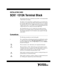
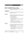
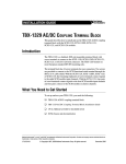
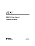
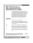
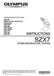
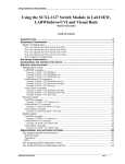
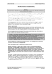
TBX-1328 High-Accuracy Isothermal Terminal Block Installation Guide This guide describes how to install and use the TBX-1328 high-accuracy isothermal terminal block with the SCXI-1120/D, SCXI-1121, SCXI-1125, or SCXI-1126 modules. Table 1 shows the signals you can use with each module. Module Millivolts/Volts Medium Voltage (60 V) High Voltage (250 V/1,000 V) Current (4 to 20 mA) Frequency to Voltage Thermocouple RTD/Thermistor Strain Gauge Force, Load, Torque Table 1. SCXI Module and Signal Compatibility SCXI-1120 Yes Yes Yes Yes No Yes No No No SCXI-1120D Yes Yes Yes Yes No No No No No SCXI-1121 Yes Yes Yes Yes No Yes Yes Yes Yes SCXI-1125 Yes Yes Yes Yes No Yes No No No SCXI-1126 Yes Yes Yes Yes Yes No No No No The TBX-1328 high-accuracy isothermal terminal block is a DIN-rail mountable, shielded terminal block with screw terminals to connect to the SCXI-1120/D, SCXI-1121, SCXI-1125, or SCXI-1126 front connector. The TBX-1328 has a high-precision thermistor for precise cold-junction compensation and isothermal copper planes that minimize the temperature gradients across the screw terminals when you take thermocouple measurements. The TBX-1328 mounts on most European standard DIN EN mounting rails. The terminal block has 24 screw terminals for easy signal connection. Eight screw terminals connect to the SCXI chassis ground through the shield of the SH32-32-A cable. With the SCXI-1120/D, SCXI-1125, or SCXI-1126, the remaining eight pairs of screw terminals connect signals to the eight LabVIEW™, Measurement Studio™, National Instruments™, NI™, ni.com™, NI-DAQ™, and SCXI™ are trademarks of National Instruments Corporation. Product and company names mentioned herein are trademarks or trade names of their respective companies. For patents covering National Instruments products, refer to the appropriate location: Help»Patents in your software, the patents.txt file on your CD, or ni.com/patents. ni.com © 1996–2003 National Instruments Corp. All rights reserved. February 2003 371207A-01 SCXI module input channels. With the SCXI-1121, four pairs of screw terminals connect signals to the four SCXI module input channels and four pairs connect to the SCXI module excitation channels. There are eight resistor sockets, R<0..7>, for use with the 4 to 20 mA current input. Conventions The following conventions are used in this guide: <> Angle brackets that contain numbers separated by an ellipsis represent a range of values associated with a bit or signal name—for example, DIO<3..0>. » The » symbol leads you through nested menu items and dialog box options to a final action. The sequence File»Page Setup»Options directs you to pull down the File menu, select the Page Setup item, and select Options from the last dialog box. This icon denotes a note, which alerts you to important information. bold Bold text denotes items that you must select or click on in the software, such as menu items and dialog box options. Bold text also denotes parameter names. italic Italic text denotes variables, emphasis, a cross reference, or an introduction to a key concept. This font also denotes text that is a placeholder for a word or value that you must supply. monospace Text in this font denotes text or characters that you should enter from the keyboard, sections of code, programming examples, and syntax examples. This font is also used for the proper names of disk drives, paths, directories, programs, subprograms, subroutines, device names, functions, operations, variables, filenames and extensions, and code excerpts. monospace italic Italic text in this font denotes text that is a placeholder for a word or value that you must supply. What You Need to Get Started To set up and use the TBX-1328, you need the following items: ❑ TBX-1328 high-accuracy isothermal terminal block ❑ TBX-1328 High-Accuracy Isothermal Terminal Block Installation Guide ❑ Read Me First: Safety and Radio-Frequency Interference TBX-1328 Installation Guide 2 ni.com ❑ SCXI chassis and documentation ❑ One of the following modules and its documentation: – SCXI-1120/D – SCXI-1121 – SCXI-1125 – SCXI-1126 ❑ SH32-32-A shielded cable assembly that includes the TBX cable adapter ❑ 3/16 in. wrench ❑ Numbers 1 and 2 Phillips screwdrivers ❑ 1/8 in. flathead screwdriver ❑ Long-nose pliers ❑ Wire cutter ❑ Wire insulation stripper Note You can download any NI document from ni.com/manuals. Connecting the Signals Note Refer to the Read Me First: Safety and Radio-Frequency Interference document before removing equipment covers or connecting or disconnecting any signal wires. To connect the field signals to the TBX-1328 for use with the SCXI-1120 or SCXI-1121, follow the labeling on the TBX-1328 indicated along with the appropriate SCXI module type column as shown in Figure 1. For the SCXI-1120D, SCXI-1125, and SCXI-1126 modules, use the SCXI-1120 label. To connect the signals, complete the following steps, referring to Figures 1 through 3 as necessary: 1. Remove the TBX-1328 terminal block cover by unscrewing the four captive cover screws in the cover corners. These screws stay attached to the cover without falling out. 2. Connect the signal wires to the screw terminals. Refer to the SCXI module user manual for examples of how to connect to field signals and loads. The chassis ground terminals are connected to the SCXI © National Instruments Corporation 3 TBX-1328 Installation Guide chassis through the cable shield. This connection is not shown in the SCXI module user manual. Allow the signal wires to exit through the TBX-1328 cover opening. Notes When using the SCXI-1121 module to measure current, you must populate R<0...7>, which corresponds to CH<0...7>. Since the SCXI-1121 can measure a maximum current of 20 mA, the minimum usable resistor value is R = 10 V ÷ 20 mA = 500 Ω. This terminal block does not provide strain relief for field signal wires. Add strain relief, insulation, and padding for the wires, if necessary. 3. Replace the TBX-1328 terminal block cover and tighten the captive cover screws. The signal connection is now complete. 4 5 6 3 3 HIGH VOLTAGE 1 1 C 7 8 2 2 250 V CAT II MAX CHANNEL-TO-CHANNEL 250 V CAT II MAX CHANNEL-TO-EARTH 1 1 1 2 3 4 5 9 Cover Mounting Nut Chassis Ground Screw Terminals Backshell Mounting Kit Cable Connector Assembly Number 6 7 8 9 Serial Number Current–Receiver Resistor Sockets R<0..7> = Channel<0..7> Signal Wire Screw Terminals Product Name Figure 1. TBX-1328 Terminal Block Parts Locator Diagram TBX-1328 Installation Guide 4 ni.com Installing the Terminal Block and Cable Assembly After completing the Connecting the Signals section, you can install the terminal block. Complete the following steps to mount the SH32-32-A cable assembly and connect the TBX-1328 to the SCXI module while referring to Figures 2 through 4 as needed. 1. Power off the SCXI chassis. 2. Power off the computer that contains the E Series data acquisition (DAQ) device or disconnect the device from the SCXI chassis. 3. Connect the TBX cable adapter to the appropriate SCXI module and secure it by tightening both thumb screws. 4 3 2 ADDRESS 5 4 3 2 1 5 1 3 1 2 3 M 2.5 Mounting Screws Cable Assembly Thumb Screws 4 5 SCXI Chassis TBX Cable Adapter Figure 2. Connecting the SH32-32-A Cable to the SCXI Module © National Instruments Corporation 5 TBX-1328 Installation Guide 4. Verify that the four backshell mounting ears on the cable assembly are in the position shown in Figure 3. If not, remove the backshell mounting ears and install them in the position shown. 3 5 4 1 2 3 1 1 2 3 Backshell Mounting Screws and Ears Safety Ground Lugs Captive Cover Screws 4 5 Terminal Block Connector Signal Wire Entry Figure 3. Connecting the SH32-32-A Cable to the TBX-1328 Terminal Block TBX-1328 Installation Guide 5. Connect one end of the cable assembly to the SCXI module front connector and secure the SH32-32-A cable by tightening both backshell mounting screws. 6. Connect the other end of the cable assembly to the TBX-1328 terminal block connector and secure the SH32-32-A cable by tightening both backshell mounting screws. 7. Reconnect the E Series DAQ device to the SCXI chassis. 6 ni.com ADDRESS 5 4 3 2 1 Figure 4. The Completed Installation Rack Mounting When you have completed the Installing the Terminal Block and Cable Assembly section, you can mount the TBX assembly in the rack. If you are using the National Instruments TBX Rack-Mount Assembly, refer to the TBX Rack-Mount Installation Guide for instructions. If you are not using this rack-mount assembly, complete the following steps to mount the TBX assembly directly onto the DIN rail: 1. Snap the TBX terminal block onto the DIN rail with a firm push. 2. Install the SCXI chassis using the appropriate chassis rack-mount kit. Note To remove the TBX terminal block from the DIN rail, place a flathead screwdriver into the slot above the terminal block base and pry it from the rail. © National Instruments Corporation 7 TBX-1328 Installation Guide Specifications All specifications are typical at 25 °C unless otherwise specified. Electrical Compatible modules SCXI-1120/D...................................8 input channels SCXI-1121.......................................4 input channels, 4 excitation output channels SCXI-1125.......................................8 input channels SCXI-1126.......................................8 input channels Cold-junction temperature-sensor circuitry Sensor type ......................................Thermistor Output range ....................................1.91 to 0.65 VDC from 0 to 50 °C Accuracy1 ........................................±0.5 °C from 15 to 35 °C ±0.9 °C from 0 to 15 °C and 35 to 50 °C Repeatability....................................±0.2 °C from 15 to 35 °C Coupling .................................................DC2 Current-receiver resistors........................Resistors not included Resistor sockets are provided for each channel Field-wiring connectors Signal screw terminals.....................16 screw terminals (8 pairs) Functional earth ground...................8 screw terminals Terminal spacing .............................0.5 cm (0.2 in.) center-to-center Maximum wire gauge......................16 AWG Strain relief ......................................none Dimensions of front entrance .................1.2 by 7.3 cm (0.47 by 2.87 in.) 1 2 This specification includes the accuracy of the temperature-sensor circuitry itself and the temperature difference between the thermistor and any screw terminal. The temperature-sensor circuitry accuracy includes manufacturing tolerances in all component values, effects caused by component-value temperature drift, voltage-divider loading, and thermistor self-heating. In instrumentation terminology, DC coupling means that both DC and AC signals are passed. TBX-1328 Installation Guide 8 ni.com Mechanical Dimensions............................................. 12.7 by 7.62 by 11.16 cm (5.0 by 3.0 by 4.4 in.) Weight.................................................... 100 g (3.5 oz) Compatible DIN rails ............................. DIN EN 50 022 DIN EN 50 035 Isothermal construction (with cover attached) Maximum Working Voltage Maximum working voltage refers to the signal voltage plus the common-mode voltage. Channel-to-earth..................................... Each channel must remain within 250 Vrms or ±250 VDC of ground, Installation Category II Channel-to-channel ................................ Each channel must remain within 250 Vrms or ±250 VDC of the voltage applied to any other channel, Installation Category II Environmental Operating temperature............................ 0 to 50 °C Storage temperature ............................... –20 to 70 °C Humidity ................................................ 10 to 90% RH, noncondensing Maximum altitude .................................. 2,000 m Pollution Degree (indoor use only) ........ 2 Safety The TBX-1328 is designed to meet the requirements of the following standards of safety for electrical equipment for measurement, control and laboratory use: • IEC 61010-1, EN 61010-1 • UL 3111-1, UL61010B-1 • CAN/CSA C22.2 No. 1010.1 Note For UL and other safety certifications refer to the product label or to ni.com. © National Instruments Corporation 9 TBX-1328 Installation Guide Electromagnetic Compatibility Emissions................................................EN 55011 Class A at 10 m FCC Part 15A above 1 GHz Immunity ................................................EN 61326:1997 + A2:2001, Table 1 EMC/EMI ...............................................CE, C-Tick and FCC Part 15 (Class A) Compliant Note For EMC compliance, operate this device with shielded cabling. CE Compliance The TBX-1328 meets the essential requirements of applicable European Directives, as amended for CE marking, as follows: Low-Voltage Directive (safety)..............73/23/EEC Electromagnetic Compatibility Directive (EMC) .....................................89/336/EEC Note Refer to the Declaration of Conformity (DoC) for this product for any additional regulatory compliance information. To obtain the DoC for this product, click Declarations of Conformity Information at ni.com/hardref.nsf/. Temperature Measurement Considerations The TBX-1328 provides high-accuracy temperature measurements for isolation modules such as the SCXI-1120/D, SCXI-1121, and SCXI-1125. The TBX-1328 provides connectivity to thermocouples, thermistors, and RTDs. The TBX-1328 provides high-accuracy thermocouple measurements using an onboard cold-junction compensation (CJC) sensor. To find out how to read the CJC, refer to the documentation for the module in use. Temperature measurements with thermistors and RTDs require excitation. The TBX-1328 provides excitation connectivity when used with an SCXI-1121. Refer to the SCXI-1121 User Manual for more information on connecting thermistors and RTDs to the excitation channels. Switch S1 switches the temperature sensor output between MTEMP (multiplexed mode) and DTEMP (parallel mode) modes. In either mode, if there are temperature variations, the measurements can be less accurate. In MTEMP mode, you must scan the temperature independently of the other TBX-1328 Installation Guide 10 ni.com channels on the SCXI-1120/D, SCXI-1121, and SCXI-1126. You can read a temperature at the beginning of the test and use that value with the data that follows. Using this method assumes that there are no temperature variations during the measurement period. If there are temperature variations, the measurements can be less accurate. When using the SCXI-1125 MTEMP can be scanned from any location in the scan list. Notes Do not place switch S1 in DTEMP mode. DTEMP mode is not supported. When using SCXI-112X modules, the TBX-1328 does not provide open thermocouple detection. To provide open thermocouple detection, you must provide a resistor to +5 V and another resistor to GND, which defeats the isolation boundary and changes the specifications. Temperature Sensor Output and Accuracy The TBX-1328 temperature sensor outputs 1.91 to 0.65 V from 0 to 50 °C. LabVIEW, Measurement Studio, and NI-DAQ can convert a thermistor voltage to the thermistor temperature for the circuit diagram shown in Figure 5. The circuit diagram in Figure 5 is optional information you can use if you want more details about the TBX-1328 temperature sensor. Note +5 V 4.7 kΩ 1% 2.5 V LM 4040 2.5 V 0.1% 2 5 kΩ 0.1% VTEMPOUT 0.1 µF –t° 1 RT (5 kΩ + 10 µF at 25° C) 2 16 V 1 2 0.1 µF Figure 5. Temperature Sensor Circuit Diagram © National Instruments Corporation 11 TBX-1328 Installation Guide In LabVIEW, you can use the Convert Thermistor Reading VI in the Data Acquisition»Signal Conditioning palette. If you are using Measurement Studio or NI-DAQ, use the Thermistor_Convert function. The VI takes the output voltage of the temperature sensor, the reference voltage, and the precision resistance and returns the thermistor temperature. Alternatively, you can use the following formulas: T(°C) = TK – 273.15 where TK is the temperature in degrees kelvin 1 T K = ------------------------------------------------------------3 [ a + b ( ln R T ) + c ( ln R T ) ] a = 1.295361 × 10⁻³ b = 2.343159 × 10 – 4 c = 1.018703 × 10⁻⁷ RT = resistance of the thermistor in ohms V TEMPOUT R T = 5,000 ------------------------------------ 2.5 – V TEMPOUT VTEMPOUT = output voltage of the temperature sensor [ T ( °C ) ]9 T ( °F ) = ----------------------- + 32 5 where T(°F) and T(°C) are the temperature readings in degrees Fahrenheit and degrees Celsius, respectively. Note Use the average of a large number of samples to obtain the most accurate reading. For example, sample for 1 second and average all the samples. Noisy environments require more samples for greater accuracy. TBX-1328 Installation Guide 12 ni.com Reading the Temperature Sensor in LabVIEW Notes This section does not apply to the SCXI-1126. When using virtual channels, select Built-in as the source of the CJC and NI-DAQ will perform compensation automatically for that thermocouple channel. You do not need to use mtemp. In LabVIEW, the channel string used to read VTEMPOUT depends on which module is connected to the TBX-1328. For more information about channel-string arrays and the SCXI channel-addressing syntax, refer to the LabVIEW Measurements Manual, which you can download at ni.com/manuals. • With the SCXI-1120/D, or SCXI-1121, use the address string: obx ! scy ! mdz ! mtemp You cannot put this channel-address string in the same channel-string array as other channels on the module that you are addressing. • With the SCXI-1125, use the address string: obx ! scy ! mdz ! cjtemp You can put this channel-address string in the same channel-string array as other channels on the same SCXI-1125 module, but it must be the first channel scanned on the SCXI-1125. Reading the Temperature Sensor in NI-DAQ Refer to the NI-DAQ Function Reference Manual for the description for reading the temperature sensor using the SCXI_Single_Chan_Setup, SCXI_Change_Chan, and SCXI_SCAN_Setup functions. Note The method for scanning the temperature sensor on the SCXI-1125 with other channels on the same module using the SCXI_SCAN_Setup is the same as that of the SCXI-1102. Strain Measurement Considerations When you use the SCXI-1121 with the TBX-1328 to measure strain, a small amount of voltage drop develops across the excitation wires in the SH32-32-A cable. This voltage drop is due to the wire resistance and the current flow in these leads when a strain gauge is connected at the TBX-1328 across the excitation outputs provided on the SCXI-1121. To reduce errors in the output voltage, first calculate the voltage drop across the SH32-32-A cable. This voltage drop results in a measurement error that © National Instruments Corporation 13 TBX-1328 Installation Guide depends on the cable length, and on the strain-gauge value and configuration. The SH32-32-A cable has a resistance (RL) of 0.21 Ω/m. Figure 6 shows a typical full-bridge strain-gauge circuit. To determine the amount of error introduced by the cable, complete the following steps: 1. Calculate the total resistance (RTL) of the cable, based on the cable length. Note Remember to include the lead resistance of both Vex+ and Vex–. 2. TBX-1328 Installation Guide Determine the bridge resistance of the strain gauge (RSG) connected at the TBX-1328. 14 ni.com RL ADDRESS 5 4 3 2 1 TBX-1328 SCXI-1121 HIGH VOLTAGE EX+ FRONT FRONT FRONT FRONT + – + – + – + – FRONT FRONT + – + – + – + – FRONT FRONT FRONT FRONT FRONT FRONT C R4 R1 R3 R2 CH+ CH– EX– 250 V CAT II MAX CHANNEL-TO-CHANNEL 250 V CAT II MAX CHANNEL-TO-EARTH RL RL RL RL Note: Each sensor lead (RL) has an added lead resistance of RL = 0.21 Ω/m Figure 6. Full-Bridge Strain-Gauge Circuit Diagram © National Instruments Corporation 15 TBX-1328 Installation Guide 3. Use the following formula to determine the total voltage drop (Vdrop) in the SH32-32-A cable excitation leads: R TL - × V ex V drop = ----------------------R TL + R SG For example, if you have a 1 m SH32-32-A cable, 120 Ω full-bridge strain gauge, and Vex = 3.333 V, then the calculations from steps 1 through 3 are: 1. RTL = 2 × 0.21 Ω/m × 1 m = 0.42 Ω; multiply the cable length by two to take into consideration both the Vex+ and Vex– lead resistances. 2. RSG = 120 Ω is the total equivalent bridge resistance as seen from the Vex+/– terminals of the TBX-1328. 3. Vdrop = 11.6 mV, which is 0.3% of the 3.333 V excitation. Now calculate the voltage drop across the field signal wires you are connecting to the TBX-1328. Perform similar calculations for the field wires as you did for the cable. Resistance can vary depending on the cable and field wires. Add this error amount to the voltage drop across the SH32-32-A cable to get a total voltage drop. You can compensate for this error along with any additional cable lead resistance introduced by the strain-gauge connection wires. One simple way of compensation is to calculate the lead resistance, then input it along with the other strain-gauge parameters into the conversion formula provided in your software applications, such as LabVIEW and Measurement Studio. To minimize resistive compensation, move the load closer to the SCXI module by using shorter cable lengths, or use heavy-gauge wire to connect to the TBX-1328.