1
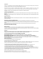
Channel 13 – Spot 4: red
Value
Function
000 – 255
Dimming from 0 – 100%
Channel 14 – Spot 4: green
Value
Function
000 – 255
Dimming from 0 – 100%
Channel 15 – Spot 4: blue
Value
Function
000 – 255
Dimming from 0 – 100%
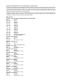
Operation via the foot switch –
Connect the foot switch with the LED Powerbar device via the 5-pin connection cable with plug. The foot switch can be operated
in sound controlled (*SND) or (AUTO) mode.
Pedal functions are as follows:
Pedal 4 Blackout press again to return to on position
Pedal 3 Hold
Pedal 2 Sound On
Pedal 1 Presets: 1 x press = White / 2 x press = Red / 3 x press = Green / 4 x press = Blue
5 x press = yellow / 6 x press = pink / 7 x press = cyan
8 x press = Colour change every second in a continuous loop as described above
9 x press = Colour fade every 3 seconds in a continuous loop as described above
To black out at any point press pedal 4. By pressing pedal 4 once more the unit will return to the previous setting.
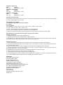
When linking two or more LED Power bars together using one foot controller
Setting up the first unit
1. Power up first unit (this will be known as the Master unit).
2. Press the left hand menu button until either AUTO or SND is displayed
3. When either AUTO or SND is displayed then choose which mode you require by pressing the centre button. AUTO = Automatic
mode, SND = Sound-to-Light mode. The master unit is now set up and ready to use.
Setting the second unit
1. Power up the second unit (this will be known as the Slave unit). Usually either AUTO or SND will be displayed.
2. Now press the left hand menu button until the display shows an (A) followed by a number. Using the right hand down button,
press until the display shows A1.
3. Now press the menu button once again, the display will show either AUTO or SND depending on the setting.
4. Press the right button and 512 will be displayed. At this point you must wait approx 20 seconds and the display will
automatically change to D1. The slave unit is now set.
5. Repeat the above section of the instructions on all other slave units that you require to be linked.
6. All Slave units must be set to D1. There can only be one Master unit.
7. Link the LED Power bars together using a 3 pin XLR to XLR DMX cable.
8. Connect the DMX Output socket on the Master unit to the DMX Input on the Slave unit. If you are connecting more LED Power
bars, connect the DMX Output of the each Slave unit to the DMX Input socket of the next unit.
Specification
Power supply: 230 V AC, 50 Hz ~
Power consumption: 160 W
Number of DMX channels: 15
DMX-512 connection: 3-pin XLR
Sound-control: via built-in microphone
Maximum ambient temperature Ta: 45° C
Maximum housing temperature TB (steady state): 60° C
Min. distance from flammable surfaces: 0.50 m
Min. distance to lighted object: 0.10 m
Number of 3x1W TCL LEDs: 28
Beam angle: 30°
Fuse: F 2 A, 250V
Dimensions (LxWxH): 1200 x 65 x 315 mm
Weight: 15 kg