1
Publication Number 0121-0461-10
Rev. A
IJl"" . . . . f\f\n
IVIClY, lo:Jo:JV
PCLA450B USER'S MANUAL
BIOMATION CORPORATION
1-9050 Pruneridge Avenue
Cupertino, CA 95014-071 b
Telephone: (800) 538'";~320
FAX: (408) 9888-1647
4~'
~o-pynght
© 1990. No part
of" this publication may be
repro.duced without writ~en
permission from BIOMATION
C.orporaticJn. Printed in U ..S.A
'"
•
',.'
PREFACE
This manual describes operation of the BIOMATION PCLA450B
system. PCLA450B is installed as a software package in an IBM
Personal Computer (PC, XT or AT) or compatible system which
serves as the host.
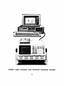
The BIOMATION K450B Logic Analyzer operates with the PC as a
peripheral unit, driven by PCLA450B to collect selected input data
and display the results on the PC screen. The K450B Logic
Analyzer operation is controlled remotely by commands entered at
the P.C. keyboard.
Information in this manual reflects the Control Software level valid on
February 4, 1988, and is up-to-date at the time of publication, but is
subject to change without prior notice.
Copies of this manual and other BIOMATION publications may be
obtained from the BIOMATION sales office or distributor, serving your
locality.
iii
K450B Logic Analyzer and Personal Computer System
iv
CONTENTS
Page
Chapter
1
GENERAL DESCRIPTION
INTRODUCTION
•
P.C. SYSTEM REQUiREMENTS
EQUIPMENT CONNECTIONS •
RS-232C Interface
Optional GPIB Interface
2
3
SOFTWARE
1-1
'1 -1
1-2
1-3
1-4
INSTALLATION
INTRODUCTION
••
PCLA450B HARD DISK INSTALLATION
PCLA450B FLOPPY DISK INSTALLATION
PCLA450B SETUP FILE
Startup Command
Information Contained in Setup File
COMMAND DESCRIPTION
2-1
2-2
2-4
2-6
2-6
2-6
2-6
IBM P.C.KEYBOARD
USER ASSISTANCE
On-Line User's Guide
Error Messages
List of Error Messages
2-9
2-10
2-10
"2-10
2-11
OPERATION
iNTRODUCTiON
•
PCLA450B TOP MENU SCREEN
TESTING PROCEDURE
SET UP FORMAT SCREEN
SET UP CLOCK SCREEN
SET UP TRACE SCREEN
.
Trace Control Command/Conditions
Standard and Simplified Trace Control
v
3- '1
3-2
3-4
3-6
3-8
3-16
3-17
3-19
ARM AND COMPARE MODE SCREEN •
ACQUISITION PARAMETERS SCREEN
PCLA USER UTILITIES SCREEN
File Utility PC DOS
File Utility K450B DOS .
PCLA Send Text Utility .
PCLA Module Version .
PCLA Terminal Utility
PCLA CONFIGURATION SCREEN
DISPLAY DATA SCREEN
DISPLAY TIMING SCREEN
HISTOGRAM SCREENS
Range Definition
Range Histogram
Link Definition .
Link Histogram
4
REFERENCE
3-22
3-27
3-29
3-30
3-32
3-35
3-36
3-37
3-39
3-43
·3-46
3-49
3-50
3-52
3-54
3-55
INFORMATION
INTRODUCTION
Warranty
Assistance
4-1
4-1
4-2
REFERENCE DOCUMENTS
4-2
ILLUSTRATIONS
Page
Figure
1-1
3-1
3-2
3-3
3-4
3-5
3-6
3-7
P.C. Equipment Connections
PCLA450B Organization of Displays
PCLA450B Top Menu Screen
Set Up Format Screen
Set Up Clock Screen .
Advanced Clock Screen
Set Up Trace Screen
Simplified Trace Control Screen
vi
1-2
3-1
3-2
3-6
3-8
3-12
3-16
3-20
3-8
3-9
3-1 0
3-11
3-12
3-13
3-14
3-15
3-16
3-17
3-18
3-19
3-20
3-21
3-22
3-23
Arm and Compare Mode Screen
Acquisition Parameters Screen •
PCLA User Utilities Menu
File Utility PC DOS Screen
File Utility K450B DOS Screen .
Send Text Utility Screen
Module Version Utility •
Terminal Utility Screen .
PCLA Configuration Screen
Display Data Screen
.
Display Timing Screen •
Histogram Utility Menu Screen .
Range Definition Screen
Range Histogram Screen
Link Definition Screen .
Link Histogram Screen .
vii
3-22
3-27
3-29
3-30
3-33
3-35
3-36
3-37
3-39
3-43
3-46
3-49
3-50
3-52
3-54
3-55
Chapter
1
GENERAL DESCRIPTION
INTRODUCTION
This manual describes operation of the SlOMATION PCLA450B
software which permits the logic analyzer to be controlled remotely by
a personal computer. PCLA450B is installed as a software package
in the IBM Personal Computer (PC, XT or AT) or compatible system.
The BIOMATION K450B Logic Analyzer operates with the PC as a
peripheral unit.
The PCLA450B program simulates the K450B Logic Analyzer setup
and data display screens on the PC video display. It communicates
with the K450B to provide a remote Logic Analyzer display and
control facility. GPIB (IEEE-488) and RS-232 communication
interfaces are supported.
The K450B Logic Analyzer is controlled remotely by PCLA450B
commands entered at the PC keyboard.
PCLA450B collects
selected input data, and displays the results on the PC screen.
PCLA450B also allows the PC to read from, write to, and display
contents of diskettes used on a stand-alone K450B Logic Analyzer.
The PCLA450B kit has one diskette labeled PCLA450B and a
User's Manual. A National Instruments GPIB board and interface cable
is available as an option.
PC SYSTEM REQUIREMENTS
The PC minimum system requirements are:
The Personal Computer is an IBM PC/XT/AT or
compatible system.
The PC should have a minimum of 512K of
RAM and one floppy disk drive.
Either a CGA Display Adapter or a EGAlVGA Display Adapter
running in CGA mode is required to display waveforms of the
Timing Screen.
A monochrome monitor and IBM MDA Display Adapter, or
Hercules Monochrome Display Adapter, may be used but will
not display waveforms of the Timing Screen.
1-1
The operating system is
jg)()8
2.0 or higher.
The Extended Screen and Keyboard Control driver
(~~W file) is installed.
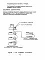
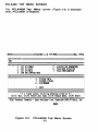
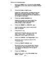
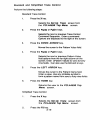
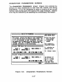
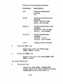
EQUIPMENT CONNECTIONS
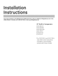
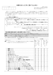
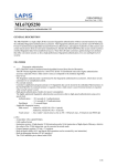
Hardware installation (Figure 1-1) conSists of connecting the K450B
Logic Analyzer to the PC via the RS-232-C or optional GPIB
interface as described in subsequent paragraphs.
HOST RS232 INTERFACE
HOST OPIS INTERFACE
RS-232-C COMMUNICATIONS
(ACCOMMODATES ONE K450B)
"
+18 '
I
(MAXIMUM»)
K4SOB
I
OPIB'
rr
,J
OPIS COMMUNICATIONS
(ACCOMMODATES ONE TO 18 K450Bs)
Figure 1-1. PC Equipment Connections
1-2
RS-232-C
Interface
A single K450B Logic Analyzer unit may be connected to the PC via
the RS-232 interface. The RS-232 port at K450B Logic Analyzer is
configured as Data Terminal Equipment (DTE) and requires a Null
Modem for Operation as described in the Logic Analyzer User's
Manual.
The RS-232 communications protocol must be set the same for both
the PC and K450B. The PCLA Configuration screen must be
accessed to set the RS-232-C protocol for the PC as described in
Chapter 3 of this manual. (See description of PCLA
Configuration Scree n.)
The K450B 110 screen must be accessed to set the RS-232-C
protocol at the Logic Analyzer as described in the Logic Analyzer
Usefs Manual. (See description of RS-232-G Interface.)
Select the following conditions for RS-232-C interface at both the PC
and Logic Analyzer:
110 PORT =
BAUD RATE =
WORD LENGTH =
STOP BITS =
PARITY =
RECORD LENGTH
PROTOCOL =
=
RS-232
9600 Max. (User defined)
8 Bits
1
NONE
unlimited
XON/OFF
1-3
Optional GPIB Interface
Up to 18 K450B Logic Analyzer units may be connected to the PC
via the optional GPIB (IEEE-488) interface. The GPIB interface
allows the PC to select and control remote operation for only one
Logic Analyzer at a time. However, PCLA can monitor the activity of
all Logic Analyzers connected in the GPIB network.
The handshake interaction for GPIB communications must be the
same for both the PC and K450B. The PCLA Configuration
screen rrust be accessed to set the GPIB handshake control as
described in Chapter 3 of this manual. (See description of PCLA
Configuration Screen.)
The K450B VO screen must be accessed to set the GPIB
handshake control as described in the Logic Analyzer User's Manual.
(See description of GPIB interface.)
Select the following conditions for GBIP interface at both the PC and
Logic Analyzer:
GPIB MODE =
TERMINATOR =
EOIOUTPUT=
VOPORT=
RECORD LENGTH =
Talk/Listen
CR
ON (set with last transmission byte)
GPIB
Unlimited
1-4
Chapter 2
SOFTWARE INSTALLATION
INTRODUCTION
This chapter describes the software installation and execution of
PCLA450B with the PC. These procedures assume the user is
familiar with~. The syntax used in these procedures is identical
to the @OS 'syntax found in the ~ Reference Manual. If an error is
made before installing a IQ)OO file, press the CtrVC keys and re-enter
the command.
Procedures are provided for installing and invoking PCLA450B on a
hard disk or a floppy disk system. Procedures are also included for
startup using the PCLA450B Setup File.
2-1
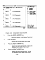
PCLA450B HARD DISK INSTALLATION
This procedure assumes that OOS is installed on the PC hard disk.
This procedure also assumes that the user is familiar with [00$. The
syntax used in these procedures is identical to the OOS syntax found
in the OO~ Reference Manual. To manually install PCLA450B on a
hard disk, perform the following:
If the files already exist for OOoolF~..sW and
simply add the information
contained in steps 3 and 6 to the respective file
using any word processor.
NOTE:
~1UJir~@.®~ir,
1.
Turn on the power at the PC disk drive and monitor.
The prompt should be ©: ~ and should be in the root
directory.
2.
Begin installing (if it does not already exist) the
file by entering ©©~Y
©OOO: OOOOIF[I@l..$Y~. The PC prompt
changes to a - (dash).
©©ooIFO@l.~Y~
3.
Enter
[Q)[gWO©{g§[~ :][[P)lIDU[h)]£[M~Oo~Y ~
It is also recommended to set the following values:
Enter
Enter
®(UJ[PIF[g~$§~@
IFn!L[g~§~@
4.
Press the Ctrt! Z and then the RETURN keys. This
creates the ©©ooIFO~.~Y~ file.
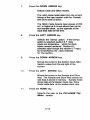
5.
Begin installing the b\(UJU©~[g©.®b\ii' file by
entering ©©~Y ©©OO: b\m©~[g©.rIDb\iJ.
6.
Enter ${g'iJ
is installed.
~~O[ID~~O[ID@,
2-2
if a GPIB board
7.
Press the Ctrll Z and then the RETURN keys.
This creates the &l\DiiO~C.~&ir file.
8.
Press the CtrllAll and Delete keys to reboot the host
computer with the new [Q}OO files.
9.
Enter iiIIDJ ~ (or any other sub-directory
name)to create the PCLA450B sub-directory.
1 O.
Change the prorll>t to &:
11 .
Insert the PCLA450B disk into the PC disk drive A.
12.
Enter OO[¥>Y *.* ©~~ (or sub-directory
path name selected).
13.
Change the prompt to ©:.
14.
Start PCLA450B by logging onto the PCLA450B
subdirectory by entering ©IQ) ~~
(or sub-directory path name selected).
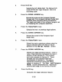
15.
To start PCLA450B, enter
~[LlM~~
(OR)
~©[1.~~@® @MftlYllP>
16.
Enter
17.
Set the GPIB or RS-232-C values in the PCLA
Configuration screen. See Chapter 3 of this
manual for more information on this screen.
2-3
va
18.
Set the GPIB or RS-232-C values in the
screen
in the Logic Analyzer. This requires a K450B
User's Manual. See Chapter 4 of this manual for
reference documents.
19.
Each screen may be displayed and parameters
modified. If a Logic Analyzer is connected,
recordings may be taken.
20.
Press the HOME key to return to the PCLA450B
Top
Menu screen from most other screens.
21 .
Press the Ctrt/C keys to exit PCLA450B.
PCLA450B FLOPPY DISK INSTALLATION PROCEDURE
The syntax used in these procedures is identical to the OOS syntax
found in the ~ Reference Manual. To manually install PCLA450B
on a floppy disk system, perform the following:
If the files already exist for OOOO[F~.sm and
simply add the information
contained in steps 4 and 7 to the respective file
using any word processor.
NOTE:
&1lJJiiO~C.~£jj',
1.
Tum on the power at the PC disk drive
and monitor.
2.
Insert and load the @tOO disk into the PC
disk drive.
3.
Begin installing the
CO~y
calM:
©OOO[FO~o~V~
file by entering
©OIM[FO~.~"~.
4.
It is also recommended to set the following values:
Enter
Enter
~01l[F[F~~~g~@
[FO!l::.~~8~@
2-4
5.
Press the Ctrll Z and RETURN
creates the COOOIPOG.SY~ file.
6.
Begin installing the ~(UJijO~C.. ~~'jj' file by
entering COWlY COOO: ~(UJijOlIDmC.~~ii.
7.
Enter ~ ~~~~OO, if a GPIB board is installed.
8.
Press the Ctrll Z and then the RETURN keys.
This creates the ~IWiiO~Ca~~ii file.
9.
Press the CtrllAit and Delete keys to reboot the PC
with the new @OO files.
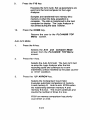
1 O.
Remove the [DXOO disk from the PC disk drive A.
11 .
Insert the PCLA450B disk into the PC disk drive A.
12.
To start PCLA450B with
enter [p)©~
keys. This
a user supplied display type,
(OR)
13.
Enter
14.
Set the GPIB or RS-232-C values in the PCLA
Configuration screen. See Chapter 3 of this
manual for more information on this screen.
15.
Set the GPIB or RS-232-C values in the 110 screen
in the Logic Analyzer. This requires a K450B
User's Manual. See Chapter 4 of this manual for
reference documents.
16.
Each screen may be displayed and parameters
modified. If a Logic Analyzer is connected,
recordings may be taken.
17.
Press the HOME key to return to the PCLA450B TOP
Menu screen from most other screens.
18.
Press the Ctrl/e keys to exit PCLA450B.
[P)©I!..M!)@IID @HftM[p).
2-5
PCLA450B SETUP FILE
Stanup Command
The startup of PCLA450B using the Setup file is invoked by entering
the program name followed by a Setup filename. The command is
entered as Follows:
The • preceding the setup filename is mandatory.
filename must follow ~~ filename format.
The setup
Information Contained In Setup File
The Setup file is a free-form ASCII file containing default information
for PCLA450B. The following list of commands presents valid
command entries and associated formats.
COMMAND DESCRIPTION
@@DI1ilt{
PC LOCAL serial port number
(or)
0'i10@@0'i10~
PC MODEM serial port number
This command selects a PC LOCAL serial port
or MODEM serial port to be used by PCLA450B.
The l[ is replaced by 1 or 2, corresponding to PC
ports COM1 : and COM2. There is no default
value for these commands.
0'i10@!ri)@
IBM Monographics card
(or)
@@D@U'
IBM Colorl Graphics card
(or)
S1!ri)~~
ANSI standard terminal
2- 6
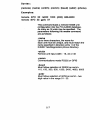
Syntax:
(remote) (name) (width) (comm) [baud] [addr] (phone)
Examples:
NIII1iJ@tt@ ~[F(Q) ~~ 11'@~~~ 11 ~@ (~@$) ~U~@@
~iliID@tt@ ~IF© ~ ~~n~ @1
This command loads a remote K450B unit
configuration into the PCLA450B database.
As many as 18 units may be specified. The
parameters following the ~ command
are as follows:
-name
Up to three characters, the name for
each unit must be unique, and must match the
name specified in directory entry of the
K450B TeleDiagnostics phone directory.
°
-width
Remote unit input width - 16, 32 or 48
-comm
Communications mode RS232 or GPIB
-baud
Must follow selection of RS232 as comm110,150,300,600, 1200,2400,4800,9600
-addr
Must follow selection of GPIB as comm - two
digit value in the range 01 - 30.
2-7
-phone
Phone number for modem controlled units.
H a phone number is specified, the unit is
assumed to be controlled via a modem.
Do not enter for GPIB Mode.
This command sets the local phone number, i.e.
the phone that is attached to PC. Hayes Modem
standard format is used. This number is sent to
remote units when the ~mo C~~~CIl(
option is selected during ARM.
This command causes PCLA to act as a virtual
Logic Analyzer. As each unit is selected on
the Top Menu screen, the complete
database describing that unit is loaded either
from disk (if C1~p) or by querying the
remote unit. Additionally, a complete data
transfer will be requested when a remote
unit calls in to PCLA. Note that PCLA will
ALWAYS request a Memory A transfer from
the remote unit when it receives a data call
from the remote. Default is no swap.
This command tells PCLA to maintain a
disk image of each remote unit and to load the
appropriate setup and data information from
disk when a remote unit is selected from the
Top Menu screen and the ~~ command is
in effect. H no data file exists for the selected
unit, PCLA will query the remote unit. H a disk
image is present for unit 00 at initialization time, it
will be loaded. Note that this option requires
approximately 11 OK of disk space per remote
unit file. Default is no @I~~Il~.
Note: Selecting a new unit while in the
PCLA Configuration screen does not
cause either ~~ operation, regardless of
the command setting.
2-8
This command sets the ~~ directory
that PCLA450B uses for saving and
recaUing setup and data files. Default is the
current directory.
This command sets the ~ directory that
PCLA450B uses when searching for help files.
Default searches PC-DOS directories in the
PATH statement for PCLA help files.
Entries may be made in any order. When entries are duplicated, only
the last occurrence will be accepted. PCLA450B ignores blank lines
and any text on a line following a semicolon (;).
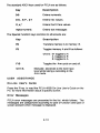
IBM PC KEYBOARD
The Standard Function keys are:
Key
Description
Home
Returns the user from the current
screen to the Top Menu screen.
PgUp (NEXT)
Changes the field to the next selection.
PgDn (PREVIOUS) Changes the field to the previous
selection.
End
Toggles Edit on/off in various screens.
Ins
Inserts data into the display.
Del
Deletes data from the display.
?
Selects Help screen (On-Line User's
Guide for screen being displayed).
Return
All data is entered and proceSSing
begins.
ARROWs
Moves the active field within the display
2-9
The standard ASCII keys used for PCLA are as follows:
Key
Description
Go9
Enters numerals.
0-9, A·F, a·f
Enters hex values.
x,x:
Enters Don1 Care values.
Alpha-numeric
Enters text messages
The Special Function keys common to all screens are:
Key
Description
F8
Transfers memory A to memory B.
F9
Toggles memory A and B as follows:
where: M toggles to A
A toggles to B
B toggles to A
Toggles the Arm cycle on and off.
F10
Ctrl/A
USER
Manually advances to the next trace
level while taking a recording in the
Arm mode.
ASSISTANCE
On-Line User's Guide
Press the? key to read the PCLA 450B On-Line User's Guide on the
PC for more information about a specific screen.
Error Messages
PCLA error messages are presented in the list which follows. The
messages are categorized according to type of function and type of
screen present when message is displayed.
2-10
List of Error Messages
General Messages
Illegal key, press '?' for more infonnation
Warning: Split timing selected
Communications Related Messages
PC DOS error
No MODE~ port installed (selected)
No Serial board installed (selected)
No GPIB board installed (selected)
Phone hung up.
Remote unit has hung up
Remote unit did NOT hang up, try again
Warning: Invalid Record Received
NAK Sent
Urecoverable communications error
NAK received
Use F10 from TOP MENU to Establish Modem Link
GPI B Related Messages
PC DOS error
Function requires PC to be Controller-in-Charge
Write detected no listeners
Interface board not addressed correctly
Invalid argument to function call
Function requires PC to be System Active Controiier
I/O operation aborted
Non-existent interface board
GPIB ErrS
GPIB Err 9
I/O operation started before previous completed
No capability for operation
GPIB Err 12
GPIB Err 13
Command error during device call
Serial Poll status byte lost
SRQ remains asserted
2-11
Trace Control Screen Messages
Illegal DELAY: values are 1 - 65535
No room for patternlcommand line
Simplified Trace Control no longer valid
Can't change memory A or B
No room for patte rnlco mmand line
Pattern not found, add to definition list? (YIN)
Cannot delete, pattern referenced in command line
Format Screen Messages
User Specified Format loaded
Cannot set User Specified from User Specified!
Can' change memory A or B
Histogram Screen Messages
Memory A only
Insufficient PC memory for requested function
PC DOS and K450B DOS Utilities Messages
Illegal command
Illegal option
Illegal filename
Working drive must be specified
Disk read error
File not found
Invalid directory
File locked
Duplicate filename
Insufficient disk space
Disk write error
Insufficient directory space
File type mismatch
Not enough memory
Checksum error
Help command argument error
Unable to open file
MS-DOS error
2-12
Data Swap Function Messages
Unable to perform disk swap
Swapping remote unit databases
Disk error during swap
Acquisition Parameters Screen Messages
Illegal value, press PgDn (PREV) to clear
Unknown error in Acquisition Parameter Screen
Timing Screen Messages
Incomplete channel selection: must enter key 0 -F
Insufficient PC memory for requested function
Can' send while remote unit is armed
Data Screen Messages
Illegal cursor value
Illegal value for C or R - Maximum value is <xxxx>
Clock Screen Messages
Illegal clock: legal values 20 nS to 100 mS
Can't change memory A or B
User Utilities Messages
8ad file or filename
insufficient PC memory for requested function
Simplified Trace Control Screen Messages
Only one OR condition may be used at a time
No room for pattern/command line
Illegal value, press PgDn (PREV) to clear
Can't change memory A or B
Can't change screens while editing
2-13
Arm Mode Screen Messages
Insufficient PC memory for requested function
Illegal value, press PgDn (PREV) to clear
Can't change memory A or B
Configuration Screen Messages
Can't open setup files: 'filename'
Error in reading setup file: 'filename'
Setup file syntax error. line <II>
COMM and MCOM cannot be equal
Unknown or illegal display type
Must specify PHONE with MCOM
Unknown setup file error
Illegal value: valid addresses are 01 - 30
2-14
Chapter 3
OPERATION
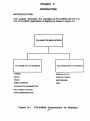
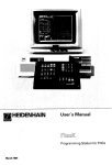
INTRODUCTION
This chapter describes the operation of PCLA450B with the P.C.
The PCLA450B organization of ·displays is shown in Figure 3-1.
PCl.A45OB TOP MENU SCREEN
PCLA450B SET UP SCREENS
PCLA450B DISPLAY SCREENS
FORMAT
DISPLAY DATA
a.oo<
DISPLAY TIMING
TRACE
HISTOGRAMS
ARM/COMPARE
I-ElP
ACQUISITION PARAMETERS
PCLA USER UTILITIES
PCt.A CONFIGURATkJN
Figure 3-1.
PCLA450B Organization Of Displays
3-1
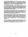
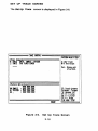
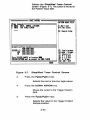
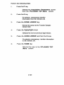
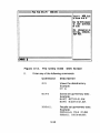
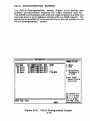
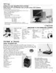
PCLA450 TOP MENU SCREEN
The PCLA450B Top Menu screen (Figure 3-2) is displayed
when PCLA450B is initialized.
HEM:"~====::}PCLA4S9B
v1tlS TOP
rmru====~MtM:
39929
::Selected
Uni t================::::l
.l!lll
~etup===================
i
F - SET UP FORMAT
C - SET UP CLOCK
x - SET UP TRACE
A- ARM AND COMPARE MODE
P - ACQUISITION PARAMETERS
U- PCLA usn UTILItIES
I - PCLA COHFIQlRATIOH
fDisplaY======D=-=DI=SP=LA=Y=DA=YA=========
T - DISPLAY TIMING
H - HISTOCRAItS
? - HELP
~ t + ~ MOue curso~t Select by frf55ing l~tte~ o~ ~
Ctl/C: Quit, CtllD: ReMOte data dUMP, ct IH: Hangup phone, CtllR: Reset
PCLA: Personal
COMpute~
- Logic
Analyze~
link,
Copy~ight
1986,87 Could, Inc.
READY
Figure 3-2.
PCLA450B Top Menu Screen
3-2
The PCLA450B Top Menu screen lists all screens used to set
and display the test results at the P.C. To select a screen, press the
ARROW key to move ~he cursor to the desired screen and press
the RETURN key. The user can also select and press the letter
displayed next to each screen. This is called the QUICK key.
The PCLA450B Top Menu screen displays the names of the
K450B remote units and aiiows the user to change ihe active remoie
unit. The top display box shows the first three characters of the
remote unit 10 names. The active remote unit is highlighted. Remote
units requesting service are displayed in reverse video, with a red
backround if a color monitor is used.
If the remote unit has a phone number, PCLA450B attempts to
establish a phone connection when the F10 key is pressed. The
phone number is displayed and the user can press the F1 key to call,
or press the F2 key to cancel. The active remote unit executes a
data dump when the Ctri/D keys are pressed.
The top line of data on all screens is the Memory Status. The
Memory Status indicates the type of memory displayed. Set Up
memory M displays the parameters selected for the next acquisition
cycle. Set Up memory A displays the parameters selected for the
acquisition cycle just completed. Set Up memory B is used for
storage of Set Up memory A data for future reference and
comparison.
The Data memories are used with certain Display screens. Data
memory A stores the data acquired during the last acquisition cycle.
Data memory B stores the data of memory A for future reference or
comparisons. Data memories A and B are seen by the user.
3-3
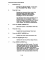
TESTING PROCEDURE
This is a procedure for connecting the logic Analyzer to a signal
generator. The user should generate a recording of an input signal. Refer
to the installation procedure of chapter 1 for specific instructions on
connecting a logic Analyzer to the P.C.
The user should have a signal generator, that provides an output timing
signal with a TTL logic level and a square wave or pulse train frequency
between 10KHz and1 MHz. Perform the following steps:
1.
Connect The Probe Cable To The Logic
Analyzer
Plug a Probe Cable assembly to the logic Analyzer
front panel input socket labeled A, ClK J, K, 7-0.
Connect the flying leads to the Probe Cables.
2.
Connect The Probe Cable to The User's
Equipment
Connect the logic Analyzer probe tip (brown wire)
labeled GND to the ground of the Signal generator.
Connect the logic Analyzer probe tip (orange wire)
labeled 3 to the signal output of the signal generator.
3.
Install PCLA450B At The Host Computer
Follow the installation procedures in Chapter 2.
After PCLA450B is installed and running, select the
PCLA Configuration screen. Select the appropriate
remote unit. See the section on the
PCLA Configuration screen in Chapter 3.
4.
Take A Recording Of The Input Signal
Press the F10 key to take a recording.
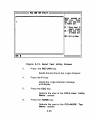
5.
Display The Results of Recorded Data
Press the HOME key to return to the PCLA450B
Top Menu screen.Press the 0 key. Verify on the
Display Data screen that the input signal trace
appears.
3-4
6.
Take Another Recording of The Input
Signal
Press the F10 key to rearm the Logic Analyzer.
7.
To Exit PClA450B
Piess the Ctrl/C keys on the host compu1ei. Exit
PCLA450B by answering Y! to the prompt.
3-5
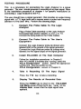
SET UP FORMAT SCREEN
The Set Up Format screen (Figure 3-3) specifies the format for
displaying data samples.
"E"="'==== DATA FORMAT =======;::::RA;;:DIX:;::MO;;D;:I;;nw;;;::=
::Data ro~t=========:===
~ MODE
lOC!
i RADIX L~ HHHH HHHH HHHH HHHH
: SECTION EIEE DDDD eccc BBBB AAAA
; INPUTS FB73 FB73 FB73 FB73 FB73
EA62 EA62 EA62 EA62 EA62
D951 »951 ~51 ~51 ~51
C849 C849 C849 C849 CS49
9 - hex
1 - octal
2 - ~inaJl!l
3 - USff SPfci£ied
Un
il'NI~
in
hinary radix MOde ;
to selfct sfctions ,
F1 - data fOrMat
F2 - top thHshold
=Threshold and
i EF-E9
I DF-D9
i CF-C9
~
BF-BQ
i AF-A9
: CLOCK INPUTS
Poial'ity======:===
TTL
TTL
TTL
+ 1.49
+ 1. 49
+ 1.49
+ 1.49
+ 1.49
TTL
TTL
TTL + 1.49
H+HH+
HHHH
HH+H+
++++++++
+HHH+
+H+++H
H+++ +++
+H+++++
++++++++
H++++++
F4 - Load UseI'
SPfcitied
F8: A-) Bxhl'
n: A lB."
Fil: ARM uni t
Figure 3-3.
Set Up Format Screen
This screen also has a section for selecting probe data input
thresholds and polarities. The format determines how data samples
are shown on the Display Data, Set Up Trace and
Histograms screens.
3-6
i
Perform the following steps:
1.
Press the HOME key to access the PCLA450B
Top Menu screen and select the Setup Format
screen.
2.
Press the PgUp or PgDn keys.
Selects the data format by scrolling through the
logical next or previous choices. Enter a value.
The options for Radix Mode field are displayed on
the far right of the screen.
3.
Press the DOWN ARROW key.
Selects the Section and Inputs fields if the
User Specified data format is specified.
Enter a value, or go to step five.
4.
Press the INSERT or DELETE keys.
Adds or deletes data. Cannot restore data
after it is deleted.
5.
Press the F2 key.
Selects the Threshold values for each data
input. Enter a value . The options are
displayed in the far right of the screen.
6.
Press the ARROW and PgUp/PgDn keys.
Enters the next or previous value for the
Threshold field.
7.
Press the RIGHT ARROW key.
Moves the cursor to the Polarity field. Selects
the polarity for each threshold. Enter a value
The options are displayed in the far right of
the screen.
8.
Press the HOME key.
Returns the user to the PCLA450B Top
Menu screen.
3-7
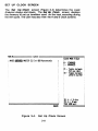
SET UP CLOCK SCREEN
The Set Up Clock screen (Figure 3-4) determines the Logic
Analyzer clocks and inputs. The Set Up Clock screen displays
the memory M set up condition used on the next recording during
the Arm cycle. The user may also view the A and B Clock screens.
~:M~====
CLOCX ======!=====~
CLOCX MODE FIELD
:I MODE vmml MASTER CLK Int 929 Nanoseconds
9 - STANDARD
1 - ADlJAHCED
Fl - Toggle betWfen
SnS and 1inS
F2 - TOfgle
~tWfen
LA CH I GLITCH
Fa: A-) Bdel'
n: A lB ••
rle: ARM uni t
Figure 3-4.
Set Up Clock Screen
3-8
The Set Up Clocks screen special function keys are:
Key
Description
F1
Forces the unit into the Advanced mode and
100/200 MHz timing for all sections.
F2
Pressing this key in the Standard mode forces the
unit into the Advanced mode. This key also selects
Glitch or Derrux for all ifl)Uts and samples all
sections at the Master Clock rate.
Perform the following steps:
Standard Internal Clock Mode
1.
Press the C key .
Selects the Set Up Clocks screen from
the PCLA450B Top Menu screen.
2.
Press the 0 key.
Selects the Standard Clock mode. The
Standard Clock mode controls clocking for all
three input sections with a Single clock
expression (I nternaVExternal).
Input data is sampled, stored or discarded
and Trace Control decisions are made at the
Master Clock rate on all sections.
3.
Press the DOWN ARROW Key.
Moves the cursor to the Master Clock field.
Enter a value from the Clock Interval field.
The options are presented at the right of the
screen. Legal values are 20 ns to 100 ms.
3-9
4.
Press the 0 key.
Selects the Internal Master Clock field.
5.
Press the RIGHT ARROW key.
Selects the Clock Interval field. Values are
displayed at the right of the screen.
6.
Press the RIGHT ARROW key.
Selects the Clock Decade field. Values
are displayed at the right of the screen.
7.
Press the HOME key.
Returns the user to the PCLA450B Top
Menu screen.
Standard External Clock Mode
1.
Press the C key.
Selects the Set Up Clocks screen from
the PCLA450B Top Menu screen.
2.
Press the 0 key.
Selects the Standard Clock mode. The
Standard Clock mode controls clocking for all
three input sections with a single clock
expression (InternaVExternal).
Input data is sampled, stored or discarded
and Trace Control decisions are made at the
Master Clock rate on all sections.
Any J or K clock input can be inverted, not
inverted or not monitored. The monitored J
clocks are ~oolQ)m together, while the
monitored K clocks are oom and the J's
are oom to the K's.
3.
Press the DOWN ARROW key.
Moves the cursor to the Master Clock field.
3-10
4.
Press the 1 key.
Selects the External Master Clock field.
5.
Press the RIGHT ARROW key.
Moves the cursor to the Clock Input
Expression fieid.
6.
Press the PgUp or PgDn keys.
Changes the active field to the next or
previous legal selection.
7.
Press the HOME key.
Returns the user to the PCLA450B Top
screen.
Menu
Advanced Internal Clock Mode
1.
Press the C key .
Selects the Set Up Clocks screen from
the PCLA450B Top Menu screen.
2.
Press the 1 key.
Selects the Advanced Clock screen
(Figure 3-5) and field.The Advanced Clock
mode allows Glitch detection, Multiplexing
and 100/200 MHz sampling for one or more
sections.
The Advanced Clock mode samples data at
different rates for each section. Trace
Control decisions are still made at the Master
Clock rate. Glitch detection, Demux and
Latch modes are selected independently.
3-11
~~M========C~K===========~========~
CLOCK NOIE FI EIJ)
MODI 'jll'!tjRlU MASTER eLK Int 928 Hanoseconds
E_
rID
8 - STArmAD
1 - ADlJANCD
_
STORE E -
11 - Toggle ~tween
5nS and llnS
011 19 Nanoseconds
F2 - Toggh
I
Ie
STORE D
OH 11 Hanoseconds
I
STORE C
OH 19 Hanoseconds
i
lATCH
~ tween
aGLITCH
I
I
:B
STORE B
OH 19 Nanoseconds
II
!
=============w=DY:::iI
STORE A
ON 19 Nanoseconds
Figure 3-5.
3.
i
I
i
IF8: A-) Bxrer
!F9: AI BMe"
lFiI: ARM uni t
Advanced Clock Screen
Press the DOWN ARROW key.
Moves the cursor to the Master Clock field.
4.
Press the 0 key.
Selects the Internal Master Clock field.
5.
Press the RIGHT ARROW key.
Selects the Clock Interval field. Values are
displayed at the right of the screen.
6.
Press the RIGHT ARROW key.
Selects the Clock Decade field. Values
are displayed at the right of the screen.
3-12
7.
Press the DOWN ARROW key.
Selects Latch and Glitch modes.
The Latch mode holds data from one or both
halves of the input section until the Sample
ar.d Store clock is active.
The Glitch mode detects input pluses of 250
mV, or higher at 5 ns and stores them at the
next sal1l'le clock, as the opposite of the
input data state at that time.
8.
Press the LEFT ARROW key.
Selects the Demux option. If the Demux
option is selected, section 8-F data
inputs are inoperative, while the clock
inputs remain functional. Section 8-F
samples data through the section 0-7 input,
but is latched by the clock selected
for the section.
9.
Press the DOWN ARROW key.
Moves the cursor to the Section Clock field.
Select a value from the top right of the
screen.
10.
Press the LEFT ARROW key.
Moves the cursor to the Sample and Store
field. The Sample and Store field selects the
rate data is stored in memory. Sample mode
stores data at the Master Clock rate. Store
mode holds data at the section clock rate.
11.
Press the HOME key.
Returns the user to the PCLA450B Top
Menu screen.
3-13
Advanced External Clock Mode
1.
Press the C key.
Selects the Set Up Clocks screen from
the PCLA450B Top Menu screen.
2.
Press the 1 key.
Selects the Advanced Clock mode.The
Advanced Clock mode allows Glitch
detection, Multiplexing and 200 MHz
sampling for one or more sections.
The Advanced Clock mode samples data at
different rates for each section. Trace
Control decisions are still made at the Master
Clock rate. Glitch detection, DelTlJx and
Latch modes are selected independently.
3.
Press the DOWN ARROW key.
Moves the rursor to the Master Clock field.
4.
Press the 1 key.
Selects the External Master Clock field.
5.
Press the RIGHT ARROW key.
Selects the Clock Input Expression field.
6.
Press the PgUp/PgDn keys.
Selects the next or previous legal choices.
7.
Press DOWN ARROW key.
Selects Latch and Glitch modes. The Latch
mode holds data from one or both halves of
the input section until the Sample and Store
clock is active. The Glitch mode detects
input pluses of 250 mV or higher at 5 ns and
stores them at the next sample clock, as the
opposite of the input data state at that time.
I
3-14
8.
Press the LEFT ARROW key.
Selects the Demux option. If the Demux
option is selected, section 8-F data inputs
are inoperative, while the clock inputs
remain functional. Section 8-F samples data
through the section 0-7 input, but is latched
by the clock selected for the section.
9.
Press the DOWN ARROW key.
Moves the cursor to the Section Clock field.
Select a value from the top right of the
screen.
1 O.
Press the LEFT ARROW key.
Moves the cursor to the Sample and Store
field. The Sample and Store field selects the
rate data is stored in memory. Sample mode
stores data at the Master Clock rate. Store
mode holds data at the section clock rate.
11.
Press the HOME key.
Returns the user to the PCLA450B Top
Menu screen.
3-15
SET UP TRACE SCREEN
The Set Up Trace screen is displayed in Figure 3-6.
IF-Tl'lce CoMlftU
TMaC~~L==========F~======~1
PATTDH VAUlt FIEIl
I X: Ion't CiH
I'; TRACE UNtIL SAMPLE: TlICCD
I-r: Hex vailles
11: TRACE FOI 81123 CLOCKS
End - Binug edi t
II
01 pal tel'll.
I
I
I
I
I
II
~~~~~II
itiUtel'ft »thai tioas
I
HHHH HHHH
~81 }]tABLE KHKH
~ 'tttJ. rttJ.
II'S: To"le IIttWfR
le1
TRIGCD
I
-
,82
Wl1 'tIJJ. rttJ.
'ttfJ. 'tttJ. rttJ.
I
n: " -) Axtn
I!:::==========::;;:;;::~I
WIY
Figure 3·6.
Pittel'ftS - bigg.J'
I "A: AdvuCf 1yI
Fa: A.) BxI fJ'
Hi: AA~I/"OP
Set Up Trace Screen
3-16
I
I
Trace Control Commands And Conditions
The Set Up Trace
screen commands are based on specific
conditions. The conditions determine if and when any given
command is executed. Up to sixteen trace levels can be specified.
Each trace level uses up to five commands.
The Trace Control primary commands are:
Command
Description
G©jj©
If the command is present, the Logic
Analyzer jumps to any level. An example is
JJlWlJIJF>ing from level 1 to level 3. JJlW~ing
from level 4 to level 4 resets the clock or
event count programmed for that level.
'ii~~©~
Records data into memory M if specified
conditions are satisified.
~jj©~
Ends recording cycle if conditions are
satisfied.
WfJ ~Dli'
Data is not saved.
the next level.
~©W ~oo©~
Advances to the next level.
BhlQ)\,#~©~s
to
The Trace Control secondary commands are:
Command
Description
/A©W ~OO©[g OfF
Advances to the next level If the command
or pattern is present or detected.
Advances to the next level if the condition is
met.
©[R1
~©jj©
DfF
©~ ~u©~ ~fF
Jumps to a specified level if the condition is
met. This has priority over BhlQ)~~©[g OfF.
Stops the Arm cycle if the condition is met.
Has priority over all other commands in the
statement.
3-17
The Trace Control secondary commands contain conditions. The
Set Up Trace screen conditions are:
Sample
Sample = Word
Sample -:t Word
Up to fifty words may be defined.
Example:
TRACE if Sample = Break 3
(where Break 3 is a user defined word.)
Delay
Count = _
clocks or patterns
-:t
>
<
~
~
On each of the eight levels, a unique delay
may be defined using the set delay function.
The delay count is set to zero every time the
Jevel is entered (see ~@y~1NKe[§ or JJU1J1Wl
commands). Each master clock increments
the delay count. If delay by patterns is
selected. then the specified pattern
increments the delay count.
Examples:
TRACE until count = 35 clocks.
Set delay to 48 counts of sample = FREEZE
TRACE until count = 48.
(Where FREEZE is a user-defined pattern.)
Compound
Conditions
Sample and Delay conditions are logically
ANDed and both must be true.
Example:
Set delay to 21 clocks. TRACE if SAM PLE =
PITCH 1 and COUNT ~21.
3-18
Standard and Simplified Trace Control
Perform the following steps:
Standard Trace Control
1.
Press the X key.
Selects the Set Up Trace screen from
the PCLA450B Top Menu screen.
2.
Press the PgUp or PgDn keys.
Selects the next or previous Trace Control
Command Sequence. Enter a command.
Options are displayed to the right of the screen.
3.
Press the DOWN ARROW key.
Moves the cursor to the Pattern Value field.
4.
Press the PgUp or PgDn keys.
Selects the next or previous Pattern Value
field options from the far right column on the
screen. Enter aPattem Values for zero to fortynine fields. Can also use the 0-9 and x keys.
5.
Press the LEFT ARROW key.
Moves the cursor to the Pattern Name field.
Enter a value. Use any printable symbol to
form a pattern name from zero to forty-nine fields.
6.
Press the HOME key.
Returns the user to the PCLA450B Top
Menu screen.
Simplified Trace Control
1.
Press the X key.
Selects the Set Up Trace screen from
the PCLA450B Top Menu screen.
2.
Press the F5 key.
3-19
Selects the Simplified Trace Control
screen (Figure 3-7). The cursor is moved to
the Pattern Value field.
tRACE CONtROL
HtTDN hUiE FIELI !
X: hl't Cut
I-r: Hex Vilas
16: Co"iI, S.tup I
;fNCe ColMa
I: tMC! UNtIL SAMPLE: TRIGaR
1: TIACE FOI 11123 CLOCKS
-
I
EiltPliti'd Inc. Conbol
HHHH HHHH HHHH
ITRIGCD it ( ~ m.1 m.1
Aim
XXXX X'il'X )
I
I
OR
X'it.(
mx xm
[PliC. TII~ SINPLE It locltion l1li
Tllem PATTDIIt !mt Dt ,"stnt top .1 CL4CXS
READY
Figure 3-7.
3.
In: " -)
15: Tog,l. Dttlf.n
P1tt .1'IIS At: Adunc. Iv
bir"
A xlu
18: A -) Bxl"
n: • II ....
FlI: .It I STOP
Simplified Trace Control Screen
Press the PgUp/PgDn keys.
Selects the next or previous legal values.
4.
Press the DOWN ARROW key.
Moves the cursor to the Trigger Position
field.
5.
Press the PgUp/PgDn keys.
Selects the value for the Trigger Position
Sample location.
3-20
6.
Press the DOWN ARROW key.
Moves the cursor to the Trigger Filter field.
7.
Press the PgUp/PgDn keys.
Selects the next or previous value for the
Trigger Finer fieid.
8.
Press the F6 key.
Compiles the Simplified Trace Control set up.
9.
Press the HOME key.
Returns the user to the PCLA450B Top
Menu screen.
3-21
ARM
AND COMPARE MODE SCREEN
The Arm and Compare Mode screen (Figure 3-8) controls the
operation of the Logic Analyzer when recordings are taken. This
includes single and multiple recordings. The Ann and Compare
Mode screen specifies the following:
Type of arm mode.
Conditions when a recording series is terminated.
HEM:"
ARM AND COMPARE MODE
=====1=====
dr'''' Mode===========::::::l
IAFTD ONE PASS,
ARM MODE
I19 - Stop alte!' one
il'M
~
cgcle.
alt!!' each
I1 - Rul'M
iI'M cgcle unless
I
!
:
:::COMpal'f Range
;AUTO COMPARE RANCE IS FOR 2948 SAMPLES
USING INPUTS DEFINED ON
rO~AT
irs:
A-) B xfel'
!F9: AI B Me"
READY
Arm
condition is Mtt.
SCREEN
AUTO EDGE TOLERANCE : ~ 9 SAMPLE(S)
Figure 3·8.
a selected Stop
IFig: ARM uni t
and Compare Mode Screen
Perform the following steps:
Manual Arm Mode
1
Press the A key.
Selects the Arm and Compare Mode
screen from the PCLA450B Top Menu
screen.
3-22
2.
Press the 0 key.
Selects the Arm Mode field. The Manual Arm
mode ~~ the Logic Analyzer after one
recording cycle.
3.
Press the DOWN ARROW key.
Moves the rursor to the Compare Sample
Range field. The Compare Sample Range field
specifies data examined during comparison.
The depth and width of the compare range is set
by modifying the Compare statement.
4.
Press the PgUp/PgDn keys.
Selects the next or previous legal options.
5.
Press the DOWN ARROW key.
Moves the cursor to the Compare Input
Mode field.
6.
Press the PgUp/PgDn keys.
Select the next or previous values using the
inputs selected below the field or inputs
defined on the Set Up Format screen.
7.
Press the DOWN ARROW key.
Selects the edge tolerance feature. Enter a
value. Edge tolerance compares the data in
memory A with memory B. PCLA stores
don't care samples in memory B. These
samples are not compared with their
counterparts in memory A. This places
tolerances around the rising and falling
edges in memory B. The Arm and Compare
Mode screen determines the tolerances
around each edge in the memory B buffer.
8"
Press the F4 key_
Executes the edge tolerance feature.
3-23
9.
Press the F10 key.
Executes the Arm cycle. Set up parameters are
sent from the host computer to the Logic
Analyzer.
Samples are transferred from memory M to
memory A when the data acquisition is
complete. The data is transferred to the host
computer for display. The Logic Analyzer is
not armed during the data transfer.
1O.
Press the HOME key.
Returns the user to the PLCA450B TOP
Menu screen.
Auto Arm Mode
1.
Press the A key.
Selects the Arm and Compare Mode
screen from the PL CA450B TOP Menu
screen.
2.
Press the 1 key.
Selects the Auto Arm field. The Auto Arm field
re-arms the Logic Analyzer after the first
recording cycle and continues to re-arm
indefinitely unless modified by the pass counter
or $u©~ condition.
3.
Press the UP ARROW key.
Selects the Comparison Count field.
Executes automatic comparison of memory
A and memory B. Auto re-arm $U@~s when
the relationship between memory A and
memory B is true. The re-arm continues and
counts the number of times it is true.
$lf(Q)~
over
on memory comparison has priority
on limit.
$ro~
3-24
4.
Press the DOWN ARROW key twice.
Moves the cursor to the Autosave Mode
field.
5.
Press the PgUp/PgDn keys.
Selects the next or previous legal option.
6.
Press the DOWN ARROW key.
Moves the rursor to the Compare Sample
Range field. The Compare Sample Range
field specifies data examined during
comparison for incrementing the comparison
counter. The depth and width of the
compare range is set by modifying the
Compare statement.
7.
Press the PgUp/PgDn keys.
Selects the next or previous legal option.
8.
Press the DOWN ARROW key.
Moves the rursor to the Compare Input
Mode field.
9.
Press the PgUp/PgDn keys.
Select the next or previous values using the
inputs selected below the field or inputs
defined on the Set Up Format screen.
1 O.
Press the DOWN ARROW key.
Selects the edge tolerance feature. Enter a
value. Edge tolerance compares the data in
memory A with memory B. PCLA 450B stores
don't care samples in memory B. These samples
are not compared with their counterparts in
memory A. This places tolerances around the
rising and falling edges in memory B. The Arm
and Compare Mode screen determines the
tolerances around each edge in the memory B
buffer.
3-25
11 .
Press the F4 key.
Executes the edge tolerance feature.
12.
Press the F10 key.
Executes the Arm cycle. Set up parameters
are sent from the P.C.to the Logic Analyzer.
Samples are transferred from memory M to
memory A when the data acquisition is
complete. The data is transferred to the host
computer for display. The Logic Analyzer is
not armed during the data transfer.
13.
Press the HOME key.
Returns the user to the PCLA450B Top
Menu screen.
3-26
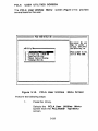
ACQUISITION PARAMETERS SCREEN
The Acquisition Parameters screen (Figure 3-9) controls the
amount of data transferred to and from the remote unit during
acquisitions. If it is not necessary to send or receive all set up and
memory data during each Arm cycle of the Logic Analyzer, transfer
time may be reduced by de-selecting the unnecessary information.
ACQUISITION PARANItIRS
i
'xrn REeORt SELECT
I: OMi t thf JlfCON
t!'OM tl'inshl'
1: bins!,!' thf
NcoN
This SCJlftn cont!'Ols tht uount of dlti tl'lllsf'PHd
to ind t!'OM thf PfMOt. unit dUlin, lcquisitions. It
it is not n.c.SSlrg to s.nd Of Ptc.iv. III s.tup
1114 MMOJIg 41h. intoPNtion on uc~ ArM ot tit uni t,
tl'iIISteJl tiM nn Itt Pfiuc.. " its. l.c til, the
unnndtd intoJINtion on tit sePt.n Mlow.
An Xindiutes I
tl'lns£'Pfd !'teoN
FTl'lfIsltl' fROM ReMOte Uni t
I
I A .. indicates in
FORMAT: X TRACI COftTROL: X II IOM1 tttd HeOM
CLOCK: ~
COMPARE MODE: X
ARM MODI:
f1 • Deflult YllufS
ImI A110M _ TO 2858 MDt B110M . . TO 2858 I
I
FTl'lnslfll TO IfMOtf Uni t
I
I
I
CLOCK: X
rORMl: X tRACI COHTROL: X
ARM MODI: X COMPARE MODI: X
I
10)1
BfROM . . TO 2851
RIAIY
Figure 3-9.
I"A: Rdnne. lul
F7: " -) Adtl'
F8: A-} Bxltl'
n:
AI B
"'M
118: ARM I STOP
Acquisition Parameters Screen
3-27
i
Perform the following steps:
1.
Press the P key.
Selects the Acquisition Parameters screen
from the PCLA450B TOP Menu screen.
2.
Press the 0 key.
De-selects unnecessary transfer
information from the remote unit.
3.
Press the DOWN ARROW key.
Moves the cursor to the Transfer Sample
Select field.
4.
Press the PgUp/PgDn keys.
Selects the next or previous legal values.
5.
Press the DOWN ARROW and then the 0 keys.
De-selects unnecessary transfer information
to the remote unit.
6.
Press the HOME key.
Returns the user to the PCLA450B TOP
Menu screen.
3-28
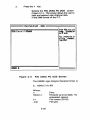
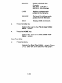
PCLA
USER UTILITIES SCREEN
The PCLA User Utilities Menu
several tools for the user.
screen (Figure 3-10) provides
==== PCU USER UTILITIES
I
F===========================~IIUn cursOI' Up ind:
!Do. to select a
~tility
1-
, 2-
1
Menu,======
l.nf:llm~IIt~
mnrrtTIy-:X458 DOS
3 . Send Text Utilitv
: 4 .. Module Uersion DIsplay
I
!uti Ii ty, then prfSS
!:Ute Enter bll; 011 .
"'III PHss nU~1I to the .
ii1dt or Mnu nw. i
!I
I, 5 • Te~inil Utilitll
Ii
'I
I,
\i
!I
Ii
ii
IIII
I,
fl
Ii
~========================:II
Figure 3-10.
PCLA User Utilities
Menu Screen
Periorm the following steps:
1.
Press the U key.
Selects the PCLA User Utilities Menu
screen from the PCLA450B Top Menu
screen.
3-29
2.
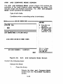
Press the 1 key.
Selects the File Utility PC DOS screen
(Figure 3-11). This screen allows the user to
save and restore Logic Analyzer data
in the IQ)OO format on the P.C.
PCLA 'ILE UTILITY - PCDOS
St... PCLA dltl 1ft4
stt~ int'PNtion
PCLA til f5 i.: C: \PCU451
II
4isk.
Fop intoJINtion.n
utilitlLP co~ds,
tg,. H •
I
I
!
;
COfIMHI: I
File Utility PC DOS Screen
Figure 3-11
The K450B Logic Analyzer filename format is:
Where:
~
!R1[g~UlJ[b'iJ
3-30
Drive
Filename up to six digits. No
embedded spaces.
File version (00-99)
File type.
The file types are:
Type Description
o~rM1
Memory M Set Up Information.
o~~
Memory A Set Up Information.
a~ rID
Memory 8 Set Up Information.
o[)i]~
Memory A Data.
a[R4]~
Memory 8 Data.
• rID~
•rID rID
Memory A Set Up Data/Information
Memory 8 Set Up Data Iinformation.
The translated
@OO filename
format is:
Where:
~
©~
~~~UJJ[bll'
oll'©
Drive
File Version.
File name.
IDXOO File Type.
The Logic Analyzer file type and
©©~ code is:
K450B
©©~
.~ [MJ
oll©
o~a,
o
o~®
oY~
o[Mj~
o
a!Ml[ID
a'ii'~
orID~
a'ii'~
arID rID
•'ii'®
3-31
'ii'~
'ii'~
Enter any of the following commands:
Command
Description
[Q) DIra
Views the diskdirectory.
Example:
[Q)O Ir
~~y~
Saves set up/memory data.
Example:
~~ V~ ~~'irI!JJ~..@~ .~1jJ
~~y~
1ra~©~11.11.
[Q)~'ir~"@'11 DIjJ~
Recalls set up/memory data.
Example:
rru~©~11.1!J~
1ra~©~11.11.
[Q)~I1.~ii'~
[Q)~lL~ii'~
3.
@'1I.~1jJ
Erases unlocked files.
Example:
[Q)~!L~1f'[g
1Xl~[bw!
[FOI1.~
[Q)~ii'~..~~t~
Displays
[,SO [l",[g",fI. fI
[Q) ~1i~a@~D[ij][ID
OO~
commands.
Press the ESC key.
Returns the user to the PCLA User
Utility Menu screen.
4.
Press the HOME key.
Returns the user to the PCLA450B TOP
Menu screen.
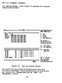
File Utility K450B DOS
2.
Press the 2 key.
Selects the File Utility K450B DOS
screen (Figure 3-12). Insert a blank or formatted
K450B disk in drive A or B of the P.C.
3-32
ICLA rILE UTILITY - 1451 lOS
Insfft
i 1451 diSkl
in drive AOf.. I
Us. tt.e JI! COMUd·
r
I
10 ,jll ~jrtclDryi
of disk.
rOf inforMation onl
IlilillLr CDRMinds,!
type H •
I
I
I
I
I
I
ILJ
II
I
COfIItm: I
Figure 3-12.
2.
File Utility K450
DOS Screen
Enter any of the following commands:
Command
Description
[Q)O~
Views the diskdirectory.
Example:
[Q)~1l' f}:,~
~f}:, ~~
Saves set up/memory data.
Example:
~[g©f}:,[L[L
~~ ~[g
~[g'iJ'(!J)~o©~ o~!Ml
~f}:, '¥I[g
@:[Q)f}:,'iJ' f}:,o©~ olMlf}:,
Recalls set up/memory data.
Example:
~[g©i!.\[b,[b,1 i!.\ lPO[b~ ©~ o~lMl
~~©f}:,[b[b
3-33
[Q)f}:,'iJ'f}:,o~©o[M]f}:,
Erases unlocked files.
Example:
[w[g!!,,[g'U'[g bl:IFO!!"[g,,,O 0
[w[g!!,,[g'U'[g [wbl'U'bl..@~ofj(]!ID
0
Applies a software write
protect to the filename.
Removes the software write
protect from the filename.
Displays 00$ commands.
3.
Press the ESC key.
Returns the user to the PCLA User Utility
Menu screen.
4.
Press the HOME key.
Returns the user to the PCLA450B TOP
Menu screen.
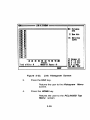
Send Text Utility
2.
Press the 3 key.
Selects the Send Text Utility screen (Figure
3-13). Enter text at the bottom of the screen.
3-34
==== PC~ SDO TIXT DTILITY =====~===~I
i
I Enter RfSSlte on!
TOO: lint.
Utt'!,i
k.g will send text',
to N.t. unit.
F1 : Clnr lonl Ii
N. te sCJlfen I
n : S.nd text
to N.te uni t I
i
ESC: Utility Menu !
til'l
I
i
I
TOO: I
Figure 3-13. Send Text Utility Screen
3.
Press the RETURN key.
Sends the text line to the Logic Analyzer.
4.
Press the F1 key.
Clears the Logic Analyzer message
and display.
5.
Press the ESC key.
Returns the user to the PCLA User Utility
Menu screen.
6.
Press the HOME key.
Returns the user to the PCLA450B Top
Menu screen.
3-35
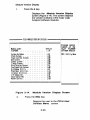
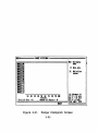
Module Version Display
1.
Press the 4 key.
Displays the Module Version Display
screen (Figure 3-14). This screen displays
the version numbers of the major Logic
Analyzer software modules.
==== PCLA MODULE VERSION DISPLAY ====1=1====
I
~========================~I
Module naMe:
SysteM DataBase
Clock Sc~en, , . , , , , , , , , ,
r~ace Control Screen, , , , ,
ArM SCl'een
,
I
I
I
I
I
I
,
I
I
I
I
I
I
,
,
,
,
I
,
,
I
I
,
I
,
I
I
I
,
I
,
I
,
,
,
,
I
,
I
I
,
I
I
I
I
I
I
I
I
Data Display Screen , , • ,
Configu~ation Screen, ,
HistogfaM Utilit~
PCLA UseI' Uti 1i tIes , ,
Internal Utilities, ,
. 1/0 SuhsysteM
Swap SuhsysteM.
HodeM Con t~o I
I
I
I
I
I
I
•
I
I
I
I
I
•
I
I
I
I
I
I
I
r
I
•
•
•
I
I
PCLA459B
1.19
Isoftware MOdules
1.91
1.99
1.99
1.99
1. 99
1.99
1. 91
1.99
1.91
1.19
1. 99
1. 91
1. 99
1. QO
:ESC: Uti Ii ty Menu
I
I
: Fo~"at SCJ'een , ,
ri Mi ng SCNen
iMaJO~
Version
PCLA4S9B, , ,
I
!Displays ve~sion
InUMhns of the
I
,
I
1
.1
1
I
1
I,
===========:===':
======
Figure 3-14.
2.
Module VerSion Display Screen
Press the ESC key.
Returns the user to the PCLA User
Utilities Menu screen.
3-36
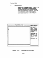
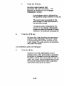
Terminal Utility
1.
Press the 5 key.
Selects the Terminal Utility (Figure 3-15)
screen. This screen is a simple terminal
emulator attached to the currently active
OO!lil: port of the host computer. The user
may talk directly to the Logic Analyzer
or a modem attached to the ~: port.
PCLA tERNINAL utILIty
TERNIMAL DIlutOR
This SCPffft is I
si"r1f t.PRiftll
.MU ItOI' ittiChti
to tilt CIlJ'Pfn tl ,
ictiv. COft: pop
ot tM PC.
I
rM IlUP MY tllk
diHctly to tM
K4Si OP i MOd."
I conD.ct.d to tM
I
popt.
Hdt-dllpl.x Mdt
Figure 3-15.
Terminal Utility Screen
3-37
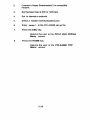
2.
Connect a Hayes Smartmodem II or compatible
modem.
3.
Set the baud rate at 300 or 1200 bps.
4.
Set to internal or external.
5.
Select a modem communications port.
6.
Enter
7.
Press the ESC key.
\liJlKG@InJi) ~
in the PCLA450B set up file.
Returns the user to the PCLA User Utilities
Menu screen.
8.
Press the HOME key.
Returns the user to the PCLA450B TOP
Menu screen.
3-38
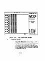
PCLA CONFIGURATION SCREEN
The PCLA Configuration screen (Figure 3-16) defines and
enables communication between the Logic Analyzer and PC.
PCLA450B communicates with only one Logic Analyzer at a time, but
can keep track of up to eighteen remote units in a GPIB network. The
active unit is identified by an arrow pointing to the unit number on the
PCLA Configuration screen.
===== COHrIQlRATIOM
~=======:::::::::=========::::j ICOfIIJHICATlOHS
UNIt NAIO:
ere COIIIIHICATIONS xrn PMOHI
i8: RS232
-)88 HOCiI
91 Zlocil
az 310cal
93 phont
48 ImJ'A "II bud
32 RS2li "88 laud
16 1$232 '688 bud
48 1$232 12a9 laud
ASCII ---ASCII ----
11: CPI B
ASCII ---ASCII Y738-48'8
II
R' Rfload s.tup
(AutoS.tup If
no FILE)
'
Inh!': Stl.ct
CW'Hnt lin.
iCtiy. unit.
I
I
is
At: Advinc. Ivl
F1: " -) Axtfr
xtu I
I n:
I ============================~":A/BMR
:,SETUP
.
fILl: s.tu,
r18: ARM I STOP i
A -) B
I
KIA",
Figure 3·16. PCLA Configuration Screen
3-39
'I
Perform the following steps:
1.
Press the I key.
Selects the PCLA Configuration screen
from the PCLA450B Top Menu screen.
RS-232-C
2.
Press the 0 key.
Selects the RS-232-C mode. Conditions for
RS-232-C linkage are:
Baud Rate:
9600 Max. (User Defined)
Word Length:
8 Bits
Stop Bit (s):
1
Parity:
None
Protocol:
XON/XOFF
Record Length: Unlimited
The Logic Analyzer should be set to
the same values.
3.
Press the RIGHT ARROW key.
Moves the cursor to the RS-232-C Baud
Rate field.
4.
Press the PgUp/PgDn keys.
Selects the next or previous baud rate in the
RS-232-C Baud Rate field.
5.
Press the RIGHT ARROW key.
Moves the cursor to the Transfer Mode field.
6.
Press the PgUp/PgDn keys.
Selects the next or previous legal values.
3-40
7.
Press the R key.
Reconfigures the communications
channels. Reloads the configuration data. If
a set up file was used, it is displayed at the
bottom of the PCLA Configuration screen.
S.
Press the DOWN ARROW key.
Moves the cursor to the Setup Filename
field. Enter the filename in the space provided.
9.
Press the HOME key.
Returns the user to the PCLA45DB Top
Menu screen.
GPIB
1.
Press the 1 key.
Selects the GPIB option. GPIB interface
conditions are:
EOI:
On (Set with last byte
of transmission.)
CR:
As Terminator
GPIBMODE:
Tall<lListen
Record Length:
Unlimited
The Logic Analyzer should be set to
the same values.
2.
Press the RIGHT ARROW key.
Moves the cursor to the GPIB Address field.
3.
Press the PgUp/PgDn keys.
Selects the next or previous legal values.
3-41
4.
Press the R key.
Reconfigures the communications
channels. Reloads the configuration data. If
a set up file was used, it is displayed at the
bottom of the PCLA Configuration
screen.
5.
Press the RIGHT ARROW key.
Moves the cursor to the Setup Filename
field. Enter the filename in the space
provided.
6.
Press the HOME key
Returns the user to the PCLA450B Top
Menu screen.
3-42
DISPLAY
DATA SCREEN
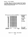
The Display Data screen (Figure 3-17) shows the data recorded
by the Logic Analyzer in the format specified in the Set Up
Format screen as numeric or ASCII values. The last sample stored
in memory is located in 2047/4095.
PC~459B
MEM:A===== DATA
Sea~ch
! 9QBQ
9991
0092
99~3
QQQ4
9905
9906
9QQ?
QQQ8
9QQ9
9Q19
9911
9912
9013
9914
9915
9916
9917
COHTROL:Q999
CLOCX:929nSEC
: XXXXX xxxx xxxx xxxx
Data
L HHHH HHHH HHHH HHHH HHHH
F 9999 9999 9999 9999 9999
F 9191 9101 9191 9191 9191
F 9292 9292 9292 9292 92B2
F 9393 9393 9393 9393 0393
F 9494 9494 9494 9494 9494
F 9595 95Q5 9595 9595 9595
F 9696 9696 9696 9696 0606
F 9797 9797 9797 9797 9797
F 9898 9898 9808 9898 QaQ8
F 9999 9999 9999 9999 99Q9
F 9A9A SA9A QA9A 9A9A 9A~
F QBQB QBQB aB9B QBQB 9BeB
F 9CQC 9Cge aeee aeee acee
F 9D9D 9D9D 9D9D 9DQD 9DeD
F BEBE 9EeE 9E9E 9E9E QEQE
F 9F9F 9F9F 9F9F 9F9F 9FQF
F 1919 1919 1919 1919 1919
F 1111 1111 1111 1111 1111
REF:2947
(R-C)+2947 (49.94 uS)
READY
Figure 3-17.
Display
3-43
Select CUl'SOl':
c:
XX~
Contl'ol
R: Refel'ence
:: Set Cul'So~
End: Edit Mode
S: SUl'ch
Q: CoMpal'e
I
In:
Page up
rF2: Page down
i
I
\
I
I
!I
I
i
i
irs: A-) Bxfer
iF9: AI BMe"
Ina: ARM uni t
Data Screen
Perform the following steps:
1.
Press the D key.
Selects the Display Data screen from the
PCLA450B Top Menu screen.
2.
Press the DOWN ARROW or PgUp/PgDn or
F1/F2 keys.
Moves the Control cursor by line or by
screen through the memory sample lines
0000 to 2047/4095.
3.
Press the C key.
Selects the Control cursor as the active
cursor.
4.
Press the PgUp or PgDn keys or directly enter a
number.
Enters the memory sample lines. Directly
enter a number with the equal (=) sign.
6.
Press the R key.
Selects the Reference cursor as the active
cursor.
7.
Press the PgUp or PgDn keys or directly enter a
number.
Enters the next or previous memory
reference sample lines. Directly enter a
number with the equal (=) sign.
a.
Press the END key.
Selects the Edit search word.
9.
Press the END key.
Exits the Edit mode.
3-44
10.
Press the S key.
Selects the Search function. The Search
function instructs the PCLA450B to examine
all stored data sa"1lles in memory A or memory
B and report the number of times a specified
word was located. Each occurrence of the
Search Word is marked with an asterisk. Husing a
color monitor, the matched samples are displayed
as yellow characters on a red background.
11.
Press the Q key.
Selects the Compare function.The Compare
parameters in the memory M controls the memory
A to B comparison. Differences between the
stored recordings are indicated by a #.
The number of miscompares is shown as well as
their locations. If using a color monitor, the
miscompare samples are displayed as yellow
characters on a red background.
12.
Press the PgUp or PgDn keys.
JJlWlRID's to the next or previous occurrence
of the Search Word or miscompare. JJlUJ~s
to the Next/Previous level if Search/Compare
is not se lected.
13.
Press the F1 or F2 keys,
Scrolls through the screen.
14.
Press the HOME key.
Returns the user to the PCLA450B Top
Menu screen.
3-45
DISPLAY TIMING SCREEN
The Display Timing screen (Figure 3-18), shows each sample
input line of data as a reconstructed waveform when using CGA
mode. (See PC System Requirements in Chapter 1 which describe
the use of CGA mode to Display Timing screen Waveforms.) The
Timing Screen indicates whether the line is at a logic High or Low,
independent of the polarity selected. The combined sample points
of all the data input sections are one trace sample. Data search and
compare functions are also supported.
tlNI",
tmt:1
tut: 4 Tl'acts
HOPiz : xl
Paff: I
lei tet (mop:
c: Cent"l
CI: ." ..Ict
:: $It CvsOP
0'
lind: Ui t ..dt
a
•111:rz: Patt"
s: StlJ'C~
•: eo"'lJIt
PIIt If
F3:~
CI
I
.pizl.tal
F4: lQM4
vutical
F6: Sfnd Tnc. I
ItScpjptionsj
• At: A4,anct lvll
total tPiCf TiMe :
COIIIIOL:_ 1EI':2151 CL:r (I-(Hll5e (41 .• d)
RUDY
CLOCI:I2InSEC
n: " -) • xftl'l
n: A
-) I xl",
n:
A II ...
FlI: •• I STOP
Figure 3-18. Display Timing Screen
Perform the following steps:
1.
Press the T key.
Selects the Display Timing screen from
the PCLA450B B Top Menu screen.
3-46
2.
Press the C key.
Selects the Control cursor as active. The
Control field is located near the bottom of
the screen. The Control and Reference
fields indicate the value of the memory
location under the Control cursor. Enter a
value.
The Control and Reference fields on the
Display Data screen and the vertical
cursor and reference lines on the Display
Timing screen are interdependent. A change
made on one screen results in an equal change
to its counterpart on the other screen.
3.
Press the R key.
Selects the Reference cursor as active. The
Reference field is located near the bottom
of the screen. Enter a value.
4.
Press the F3 key.
Expands the horizontal Display Timing
screen in increments of X1, X10, X20 and X40.
7.
Press the F4 key.
Expands the vertical Display Timing
screen by increments of 8, 4 and 16 traces.
8.
Press the END key.
Selects the Edit Mode in the left of the
screen that assigns labels and identifiers.
Enter a value.
9.
Press the PgUp or PgDn keys.
Changes inputs by moving the active cursor to
next or previous input 10 fields for entering new
numbers. Sets input labels by moving the active
cursor to the desired column.
3-47
10.
Press the UP, DOWN, LEFT, RIGHT ARROW keys.
Selects the option that alters data in memory
B. Enter a value.The cursor may be
moved to the trace area and used as an
editing cursor.
11.
Press the END key.
Exits the Edit mode.
12.
Press the S key.
Selects the Search functkm. The search
function asks the Logic Analyzer to examine
all stored samples and report the number of
times a specified word was located.
13.
Press the Q key.
Selects the compare function. Differences
between the two stored recordings are
indicated by dotted traces. The number and
locations of miscompares is shown at the
bottom of the screen.
14.
Press the PgUp or PgDn keys.
JJlUl~
to the next or previous occurrence
of the search word or miscompare.
15.
Press the HOME key.
Returns the user to the PCLA450B Top
Menu screen.
3-48
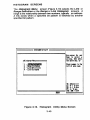
HISTOGRAM
SCREENS
The Histogram Menu screen (Figure 3-19) selects the Link or
Range Definition or the Range or Link Histogram screens. A
range is the relationship between two numbers, typically an address.
A link exists when a specified bit pattern is followed by another
specified bit pattern.
===== HISIOCRAN UTILITY =====1=====
,
I
USt cursor
FlistOffU
NfnUl===~
il:~
i 3 - Link htini tions
I
Up &Ad I
h. to Sfltct il
uti 1i ty, thtn PI'fSS I
tht InttP ktg; 01'
PHss n_1' to tilt I
Itft of MRU niM. I
4 - Link Histo!1'u
I!
II
I
i
At: Adv&Ace 1v1
1'7: " -) A xlu
n:
n:
A -) B xltl'
AII Me..
t:::============d Fl.: AIN I STOP
IIAIY
Figure 3-19. Histogram Utility Menu Screen
3-49
I
I
I
i
Perform the following steps:
1.
Press the H key.
Selects the Histogram Utility Menu screen
from the PCLA450B Top Menu screen.
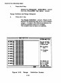
Range Definition and Range Histogram
2.
Press the 1 key.
The Range Dennltlon screen (Figure 3-20)
defines the beginning and end of up to sixteen
ranges. A range is the difference between the
least and greatest values of a variable.
The variable may be data or an address.
===== RAta tD'INITIOM =====F;;;;;;:;:::::;:;;::;;:::
PAtTIIN _ fiELD
i
HHHH HHHI 18HII==========I1
Iii
• --_ X'il'X rt.a XXXX
I US, IRU~ 'I'i"hll,
. "IUII'I'
PINIo,O
\NVV \MN vu.N
sYMols t. I.",
I "tt'N nw.
AAAA AMA AMA
11 M""181 : XXXX XXXX XXXX
o: XXXX XXXX xm
12 1KI,12 : XXXX XXXX XXXX
o: X'il'X rta XXXX
·13 RAtICI,13 : X'il'X XXXX rtt(
o: 'tlI1. XXXX xxxx
14 MHCI,IN : XXXX XXXX XXXX
o: XXXX XXXX XXXX
15 PJIICI,1I5 : XXXX XXXX m1
o: XXXX XXXX XXXX
ESC: listo"u
Mnu
n: Histofl'u
SCH.n
" lANCE,.o:: xxxx
rt.a m
XXXX XXXX XXXX
11 MIICI,11 : XXXX XXXX XXXX
o: rtt1 XXXX XXXX
II 1A1G,. : xxxx xxxx XXXX
At:
o: XXD XXXX XXIX
., 1Il1lCI," : XXXX XXXX XXXX
o: XXX'.( XXD XXXX
Figure 3-20.
A~vlftC.
Ivl
n:
" -) A xI'l'
Fa: • -) J xllP
n: • I J ....
FlI: A. I SlOP
Range
3-50
Definition Screen
3.
Press the UP or DOWN ARROW keys.
Moves the cursor in the Pattern Name field
from range 00 to 15.
4.
Press the LEFT or RIGHT ARROW keys.
Moves the cursor to the Pattern Value field.
5.
Press the PgUp or PgDn keys.
Selects the values of the Pattern Value field.
X sets don' cares and 0 to F sets the Hex
values.
6.
Press the F1 key.
Selects the Range Histogram
(Figure 3-21).
screen
The Range Histogram screen displays
the number of samples falling within each
defined range as a percent of the total
number of samples.
The data is represented in three different
ways:
Next to each range is a bar with a
length related to the percent
values on the x axis of the graph.
At the end of the bar is the
percentage.
The actual number of samples
falling within that range.
3-51
..
lANCE HISfaM
MDtA
MIG__
I
1St: lis'ItPM
JIMQ:_11
==1
1:1
ill
Z: 7tN
~tl
SCJlt8
MHQ:~
MllCIJI
=31
=3~
1_
II 21 31 41 SI " 71 81 91
hPC.Rt
, ~p.1 PISS.S : I
lobl ot Hi ts : I
Ibn
Figure 3·21.
AA: Aivanct 1,1
n: " -) • de,
11: A-) Bxl.,
n: AII ....
FlI: tit, STOP
Range Histogram Screen
3-52
I
j
f1: Itlini till
IJlAHCEJ5
I
I
:
7.
Press the F10 key.
Arms the Logic Analyzer and
generates the trace recording. The
following is displayed on the Range
Histogram screen:
A percentage value is indicated for
the specified range selected in step six.
The count value is present for the
total number of Hits that occured in
the specified range.
The pass count is indicated at the
bottom of the Range Histogram
screen to show the number of times
memory A is analyzed and graphed.
8.
Press the F1 0 key.
Re-Arrns the Logic Analyzer and generates
another trace recording. The count value
is incremented for the total number of Hits
in all ranges.The pass count is incremented
with each Arm cycle.
Link Definitions and Link Histogram
2.
Press the 3 key.
Selects the Link Definitions screen
(Figure 3-22). A link exists when a specified
bit pattern is followed by another specified
bit pattern. Since don't care patterns may be
used, the Link is a good analysis tool to find
the area of memory from which a specified
sub-routine entry point is called.
3-53
LUI IEFINITloti
PlnEII l1li IIILI
Us, 1ft, "i.tol,
sy.l s tt re",
---HII _ BRIH .
• !!ltl . : xxxx XXXI xxxx
flDI : XXXX XXXI xxxx
11 LIllfIII1 : XXXX XXXI xxxx
III : XXXX XXXI xxxx
IZ LINK IZ: XXIX mx xxxx
fHDt : XXIX mx xxxx
13 LItI 13: XXIX XXXI xxxx
fHDt : xxxx mx m1
14 LI II 14: XXIX XXXI DXX
fHllI : XXIX XXXI XXXX
185 LINlfHl5 : XXXX XXXX m1
III : XXXX XXXX XXXX
LI"\."
XXXX XXXI
III :: XXXX
XXXI XXXX
XXXX
81
1
LllllfH17 : XXXX mx XXXX
IN : XXXX XXXI XXXX
188 LINK 18: XXXX x:ax XXXX
fIIDt : XX[( mx XXXX
i89 LUCKfHDt89:: XXXX
XXXI XXXX
XXXX XXXI ).'XXX
I
pitt,... nat.
ISC: Ii 5ttll'UI
RHI
F1: •i 5tOIl'UI
SCN.n
I"
At : Idunc. Iv 1
F7: " -) Axl.1'
n: A -) B xl.,
F9: I II ...
RUDY
Figure 3-22.
3.
FlI: 1111 STOP
Link Definitions Screen
Press the F1 key.
The Link Histogram screen (Figure 3-23)
displays a sequence of two patterns the user
has defined as constituting a link. Each
character or bit in a predefined sample is set
to a value or don't care. Each link is assigned
a user-supplied name. By default, each link
is assigned LINK_XX.
3-54
LIIIIIISTOCIIII
fD:t
ISC: list.,.u
••
HII
LIIIZ
Z: ZeN dlti
HH(I
LINK 15
11: JdillititD
SCPHft
LIit[
LIIII_ "rI
LINK •
ILINf 89
LINJ( II
LItOCll
LIJOC 12
LINX_ 13
LINX_ 14
LINK_IS
I
II 21 3t 41 51" 71 .. ,. I_
Pucent
Totll 01 Hi ts : I
, ~p 01 PlSS'S : I
WIY
Figure 3-23.
3.
At: Adv•• IvI
n: II -) A xl.!'
n: A-) B xlel'
n: A II."
Fl.: AliI STOP
Link Histogram Screen
Press the ESC key.
Returns the user to the Histogram Menu
screen.
4.
Press the HOME key.
Returns the user to the PCLA450B Top
Menu screen.
3-55
t
Chapter 4
REFERENCE INFORMATION
INTRODUCTION
This chapter provides customer service and reference information.
warranty
All software products which are licensed by BIOMATION and listed in
BJOMATION's current Products Price List are furnished "as is"
without warranty of any kind, either expressed or implied; except that
BIOMATION warrants media upon which such software is delivered to
the licensee will be free from any defects in material and workmanship
for a period of 90 days from the time of shipment.
If any such medium proves defective during this warranty period,
BIOMATION will provide a replacement in exchange for the defective
medium. BIOMATION does not warrant that the functions contained
in the software product will meet customer's requirements or that
operation of the programs will be uninterrupted or error-free or that
errors will be corrected.
BIOMATION will correct all reported substantial non-conformities in
unaltered media for 90 days from time of shipment, provided such
reports are made in accordance with BIOMATIONS's standard
reporting procedure, and such non-conformities are confirmed by
BIOMATION.
4-1
Assistance
For assistance with this product, call BIOMATION Customer Service
on the nationwide toll free hot-line number: (800) 538-9320; then
dial 2 to contact the Marketing Department.
REFERENCE DOCUMENTS
The following documents are used with this manual:
K450B User's Manual, 0121-0460-10
This document describes the setup and operation of
the stand-alone K450B Logic Analyzer.
GPIB-PC User Reference Manual, 320014-01
This document describes how to install and configure the
National Instruments GPIB-PC card and cable with the PC.
4-2
Reader Comments
~BIOMATION
BIOMATION CORPORATION
19050 Pruneridge Avenue, Cupertino, CA 95014
Phone (800) 538-9320; FAX (408) 988·1647
The manual's completeness, accuracy, organization, usability, and reliability
Did you find errors in this manual? _ _ _ _ _ _ _ _ How can this manual be improved? _ _ _ _ _ _ _ _ __
Additional comments. _ _ _ _ _ _ _ _ _ _ _ _ _ _ _ _ _ _ _ _ _ _ _ _ _ _ _ _ _ _ _ _ _ __
Name _ _ _ _ _ _ _ _ _ _ _ _ _ _ _ Deparlment _ _ _ _ _ _ _ _ __ Daw _______________
Company _ _ _ _ _ _ _ _ _ _ _ _ _ _ _ _ _ _ _ _ Manual or Part No
Address
City _ _ _ _ _ _ _ _ _ _ _ _ _ _ _ _ _ State ______ Zip _ _ _ _ Phone _ _ _ _ _ _ _ __
111111
NO POSTAGE
NECESSARY
IF MAILED
INTHE
UNITED STATES
BUSINESS REPLY MAIL
FIRST CLASS PERMIT
NO. 719
CUPERTINO. CALIFORNIA
POSTAGE WILL BE PAID BY ADDRESSEE
~. BIOMATION
19050 PRUNERIOGE AVE.
CUPERTINO, CALIFORNIA 95014-9976
11.1 ••• 1.1.11 •••••• 11.1 •• 11.1 •• 1.1 •• 1••• 11 •• 1.1 •• 1. ~