1
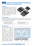
"Naples" PC Lamp/Reel/Switch Controller User Manual
nd
Issue 1.1 2 October 06
This document is the property of Aardvark Embedded Solutions Ltd and may not be reproduced in part or in
total by any means, electronic or otherwise, without the written permission of Aardvark Embedded Solutions
Ltd. Aardvark Embedded Solutions Ltd does not accept liability for any errors or omissions contained within
this document. Aardvark Embedded Solutions Ltd shall not incur any penalties arising out of the adherence to,
interpretation of, or reliance on, this standard. Aardvark Embedded Solutions Ltd will provide full support for
this product when used as described within this document. Use in applications not covered or outside the
scope of this document may not be supported. Aardvark Embedded Solutions Ltd. reserves the right to amend,
improve or change the product referred to within this document or the document itself at any time.
"Naples" PC Lamp/ Reel/ Switch Interface Hardware Manual
Issue 1.1 2
nd
October 06
Table of Contents
Table of Contents.............................................................................................................................. 2
Revision History ................................................................................................................................ 3
Introduction ....................................................................................................................................... 4
Purpose of Document.................................................................................................................... 4
Intended Audience......................................................................................................................... 4
Document Layout .......................................................................................................................... 4
Board Layout..................................................................................................................................... 5
Peripheral Connections..................................................................................................................... 6
Power Connection ......................................................................................................................... 6
Vacuum Fluorescent Display Connection ..................................................................................... 6
USB Connection ............................................................................................................................ 6
Lamp Connection .......................................................................................................................... 7
Reel Lamps................................................................................................................................ 8
Reel Connection ............................................................................................................................ 9
Switch Connection....................................................................................................................... 11
Diagnostic Connection ................................................................................................................ 12
Printer Connection (Not Yet Supported) .................................................................................. 13
Disclaimer ....................................................................................................................................... 13
CONFIDENTIAL
Not to be disclosed without prior written permission from Aardvark Embedded Solutions Ltd
Page 2 of 13
"Naples" PC Lamp/ Reel/ Switch Interface Hardware Manual
Issue 1.1 2
nd
October 06
Revision History
Version
1.0 - Draft
1.1 - Draft
1.2 - Draft
Date
14-Sep-06
02-Oct-06
27-Feb-07
Author
A. Graham
A. Graham
D Bush
Description
Initial draft.
Added annotated board layout picture.
Updated for new board layout
CONFIDENTIAL
Not to be disclosed without prior written permission from Aardvark Embedded Solutions Ltd
Page 3 of 13
"Naples" PC Lamp/ Reel/ Switch Interface Hardware Manual
Issue 1.1 2
nd
October 06
Introduction
Purpose of Document
This document describes the hardware interface to the AES "Naples" PC Lamp/ Reel/ Switch
Controller (PLRSC) as required by a game manufacturer who wishes to connect this to his game
peripherals.
Intended Audience
The intended audience of this document is the hardware engineers who will be producing wiring
harnesses to connect the PC to the reels, lamps, switches and vacuum fluorescent display.
Document Layout
The document describes the connectors on the Naples board, with pin-outs.
For the multiplexed lamps and switches, a short description of how the lamps and switches are
intended to be driven/ connected is included.
CONFIDENTIAL
Not to be disclosed without prior written permission from Aardvark Embedded Solutions Ltd
Page 4 of 13
"Naples" PC Lamp/ Reel/ Switch Interface Hardware Manual
Issue 1.1 2
nd
October 06
Board Layout
The following diagram shows the various connections to the Naples board.
The polarity of the six-way (2 + 4) power connector should be particularly noted, as pin 1 is at the
opposite end of that connector to the pin 1 of each of the other connectors on that board edge.
Connecting the power to the board using the incorrect polarity will result in catastrophic damage to
the Naples board.
Pin 1
Low Side
Lamp Drivers
Pin 1
J5
J15
VFD
J4
Power
Note: Pin 1
Location
J19
High Side
Lamp Drivers
Pin 1
J2
J3
J6 J7 J8 J9 J10J11J12J13
Pin 1
J17
Printer
Pin
J16
Diagnostics
USB
Pin 1
J14
Switch Inputs
CONFIDENTIAL
Not to be disclosed without prior written permission from Aardvark Embedded Solutions Ltd
Page 5 of 13
"Naples" PC Lamp/ Reel/ Switch Interface Hardware Manual
Issue 1.1 2
nd
October 06
Peripheral Connections
Power Connection
A 2-way JST connector is provided for logic power to be supplied to the board, and a 4 way JST
provides the power for the lamps and reels. In order to avoid problems due to noise on the earth
lines the 0v supply for these three connectors should only be connected at the power supply itself.
It is important that the 12V supply to the board must be clean and regulated.
The pinout is as follows:
Pin
Number
1
2
1
2
3
4
Connector J19 (Power)
Signal
12 Volt Logic Supply
Ground
48 Volt Lamp Supply
0v Lamp return
12 / 24 Volt Motor Supply
0v Motor return
Note that all three supplies are complete separate, and must all be fed directly from the power
supply itself.
Vacuum Fluorescent Display Connection
The Naples board provides a facility to connect a standard (Starburst) vacuum fluorescent display.
This is achieved via connector J15, which is a 6-way Molex KK connector.
The pinout of connector J15 is as follows:
Connector J15 (VFD)
Pin
Signal
Number
1
12 Volts
2
/SCLOCK
3
No
Connect
4
/SDATA
5
RESET
6
Ground
USB Connection
The board is connected to a PC using a standard Type A – Type B USB cable.
The connector on the Naples board is a Type B connector. The USB interface uses USB V 1.1.
CONFIDENTIAL
Not to be disclosed without prior written permission from Aardvark Embedded Solutions Ltd
Page 6 of 13
"Naples" PC Lamp/ Reel/ Switch Interface Hardware Manual
Issue 1.1 2
nd
October 06
Lamp Connection
The lamps are driven in a multiplexed fashion, with 16 high-side drivers and 16 low-side drivers.
This provides for a maximum of 256 lamps, though on lower-cost variants of the board not all of the
driver transistors will be fitted.
The remainder of this section assumes that all driver transistors are fitted.
In order to drive each multiplexed bulb, it needs to be connected to the intersection between a highside driver transistor and a low-side driver transistor with a series diode.
The following diagram shows a typical connection of a set of filament lamps, with associated
diodes, together with how these lamps will be addressed from within the game.
High Side 0
0
1
2
High Side 1
16
17
18
33
34
High Side 2
32
Low Side 3
Low Side 2
Low Side 1
Low Side 0
High Side 3
Bulb Number = (High Side Driver Number * 16) + Low Side Driver Number
The bulbs are driven by turning on a single high-side driver transistor and a pattern of low side
driver transistors, causing up to 16 bulbs to be illuminated simultaneously.
Let us consider these bulbs as standard 12-Volt, 1.2-Watt bulbs. If they were to be driven in a nonmultiplexed fashion, then 12 volts would be applied and they (unsurprisingly) would dissipate 1.2
Watts.
th
Each high side driver transistor is driven for a 1/16 duty cycle, so we obviously have to over-drive
the bulbs by a factor of 16 during the “on” period if we are to maintain the same power dissipation.
The power dissipated is equal to the square of the voltage divided by the resistance of the bulb.
Since we require sixteen times the power, we need to multiply the voltage by four.
For 12-Volt bulbs, we therefore need to supply 48 Volts to the Naples board.
CONFIDENTIAL
Not to be disclosed without prior written permission from Aardvark Embedded Solutions Ltd
Page 7 of 13
"Naples" PC Lamp/ Reel/ Switch Interface Hardware Manual
Issue 1.1 2
nd
October 06
If other bulbs are used, then the voltage supplied could be adjusted to suit. However, the switch
read mechanism relies on the 48-volt bulb supply and will not work correctly with other voltage
bulbs.
The connectors to the lamp matrix are achieved via four, 10-way Molex KK connectors, as follows:
•
•
•
•
Connector J2 – Lamp High Side Drivers
Connector J3 – Lamp High Side Drivers
Connector J4 – Lamp Low Side Drivers
Connector J5 – Lamp Low Side Drivers
0 .. 7
8 .. 15
0 .. 7
8 .. 15
The pin-outs of each of these four connectors are as follows:
Pin
1
2
3
4
5
6
7
8
9
10
Connector J2
Signal
High 0
No Fit
High 1
High 2
High 3
High 4
High 5
High 6
High 7
N/C
Pin
1
2
3
4
5
6
7
8
9
10
Connector J3
Signal
High 8
High 9
No Fit
High 10
High 11
High 12
High 13
High 14
High 15
N/C
Pin
1
2
3
4
5
6
7
8
9
10
Connector J4
Signal
Low 0
Low 1
Low 2
No Fit
Low 3
Low 4
Low 5
Low 6
Low 7
N/C
Pin
1
2
3
4
5
6
7
8
9
10
Connector J5
Signal
Low 8
Low 9
Low 10
Low 11
No Fit
Low 12
Low 13
Low 14
Low 15
N/C
Reel Lamps
In many reel assemblies, the reels have bulbs fitted to illuminate the win line, together with the lines
above and below the win line. On the Naples board, tracking is provided to each standard reel
connector to drive the bulbs within the reel assemblies.
It should be noted that if the standard reel connectors are used to drive to the reel bulbs, then the
reel assemblies that have a common anode diode arrangement must be used.
A high side driver is connected to each common anode (0 .. 7) and the top, middle and bottom
bulbs of each reel are connected to consecutive low side drivers 0, 1 and 2. This means that the
bulbs within the reel assemblies occupy the following positions (bulb numbers) within the bulb
matrix:
Top
Middle
Bottom
Reel 0
0
1
2
Reel 1
16
17
18
Reel 2
32
33
34
Reel 3
48
49
50
Reel 4
64
65
66
Reel 5
80
81
82
Reel 6
96
97
98
Reel 7
112
113
114
In a situation where the reel bulbs are being driven via the standard reel connectors, then the
corresponding bulb positions should not be populated in the main bulb matrix.
CONFIDENTIAL
Not to be disclosed without prior written permission from Aardvark Embedded Solutions Ltd
Page 8 of 13
"Naples" PC Lamp/ Reel/ Switch Interface Hardware Manual
Issue 1.1 2
nd
October 06
Reel Connection
A fully-populated Naples board can control 8 reels.
Each reel is connected via a standard, 0.1-inch pitch, 17-pin connector, which is pin-compatible with
standard reels.
The pinout of each of these eight connectors is as follows:
Connector J6
(Reel 0)
Pin
Signal
1
Motor +V
2
Motor +V
3
Red
Phase
4
Yellow
Phase
5
Violet
Phase
6
Black
Phase
7
No Fit
8
No
Connect
9
+5 V Opto
10
Home
Sense
11
0 V Opto
12
Top
Bulb (-)
13
Middle
Bulb (-)
14
Bottom
Bulb (-)
15
Bulb
Common
(+)
16
No
Connect
17
No
Connect
Connector J7
(Reel 1)
Pin
Signal
1
Motor +V
2
Motor +V
3
Red
Phase
4
Yellow
Phase
5
Violet
Phase
6
Black
Phase
7
No Fit
8
No
Connect
9
+5 V Opto
10
Home
Sense
11
0 V Opto
12
Top
Bulb (-)
13
Middle
Bulb (-)
14
Bottom
Bulb (-)
15
Bulb
Common
(+)
16
No
Connect
17
No
Connect
Connector J8
(Reel 2)
Pin
Signal
1
Motor +V
2
Motor +V
3
Red
Phase
4
Yellow
Phase
5
Violet
Phase
6
Black
Phase
7
No Fit
8
No
Connect
9
+5 V Opto
10
Home
Sense
11
0 V Opto
12
Top
Bulb (-)
13
Middle
Bulb (-)
14
Bottom
Bulb (-)
15
Bulb
Common
(+)
16
No
Connect
17
No
Connect
Connector J9
(Reel 3)
Pin
Signal
1
Motor +V
2
Motor +V
3
Red
Phase
4
Yellow
Phase
5
Violet
Phase
6
Black
Phase
7
No Fit
8
No
Connect
9
+5 V Opto
10
Home
Sense
11
0 V Opto
12
Top
Bulb (-)
13
Middle
Bulb (-)
14
Bottom
Bulb (-)
15
Bulb
Common
(+)
16
No
Connect
17
No
Connect
CONFIDENTIAL
Not to be disclosed without prior written permission from Aardvark Embedded Solutions Ltd
Page 9 of 13
"Naples" PC Lamp/ Reel/ Switch Interface Hardware Manual
Pin
1
2
3
4
5
6
7
8
9
10
11
12
13
14
15
16
17
Connector J10
(Reel 4)
Signal
Motor +V
Motor +V
Red
Phase
Yellow
Phase
Violet
Phase
Black
Phase
No Fit
No
Connect
+5 V Opto
Home
Sense
0 V Opto
Top
Bulb (-)
Middle
Bulb (-)
Bottom
Bulb (-)
Bulb
Common
(+)
No
Connect
No
Connect
Pin
1
2
3
4
5
6
7
8
9
10
11
12
13
14
15
16
17
Connector J11
(Reel 5)
Signal
Motor +V
Motor +V
Red
Phase
Yellow
Phase
Violet
Phase
Black
Phase
No Fit
No
Connect
+5 V Opto
Home
Sense
0 V Opto
Top
Bulb (-)
Middle
Bulb (-)
Bottom
Bulb (-)
Bulb
Common
(+)
No
Connect
No
Connect
Pin
1
2
3
4
5
6
7
8
9
10
11
12
13
14
15
16
17
Issue 1.1 2
Connector J12
(Reel 6)
Signal
Motor +V
Motor +V
Red
Phase
Yellow
Phase
Violet
Phase
Black
Phase
No Fit
No
Connect
+5 V Opto
Home
Sense
0 V Opto
Top
Bulb (-)
Middle
Bulb (-)
Bottom
Bulb (-)
Bulb
Common
(+)
No
Connect
No
Connect
Pin
1
2
3
4
5
6
7
8
9
10
11
12
13
14
15
16
17
nd
October 06
Connector J13
(Reel 7)
Signal
Motor +V
Motor +V
Red
Phase
Yellow
Phase
Violet
Phase
Black
Phase
No Fit
No
Connect
+5 V Opto
Home
Sense
0 V Opto
Top
Bulb (-)
Middle
Bulb (-)
Bottom
Bulb (-)
Bulb
Common
(+)
No
Connect
No
Connect
CONFIDENTIAL
Not to be disclosed without prior written permission from Aardvark Embedded Solutions Ltd
Page 10 of 13
"Naples" PC Lamp/ Reel/ Switch Interface Hardware Manual
Issue 1.1 2
nd
October 06
Switch Connection
The switches are read in a multiplexed fashion, using the same 16 high-side drivers (and
connectors) that are used for lamps and reading eight switches at a time though a dedicated
connector.
This provides for a maximum of 128 switches, though on lower-cost variants of the board not all of
the high-side driver transistors will be fitted.
The remainder of this section assumes that all driver transistors are fitted.
In order to read each multiplexed switch, it needs to be connected to the intersection between a
high-side driver transistor and a low-side driver transistor with a series diode.
The following diagram shows a typical connection of a set of switches, with associated diodes,
together with how these switches will be addressed from within the game.
High Side 0
0
1
2
High Side 1
8
9
10
15
16
17
High Side 2
Switc h Input 3
Switc h Input 2
Switc h Input 1
Switc h Input 0
High Side 3
Switch Number = (High Side Driver Number * 8) + Switch Input Number
The connectors to the switch matrix are achieved via three, 10-way Molex KK connectors, as
follows:
•
•
•
•
Connector J2 – Lamp High Side Drivers
Connector J3 – Lamp High Side Drivers
Connector J4 – Lamp Low Side Drivers
Connector J5 – Lamp Low Side Drivers
0 .. 7
8 .. 15
0 .. 7
8 .. 15
CONFIDENTIAL
Not to be disclosed without prior written permission from Aardvark Embedded Solutions Ltd
Page 11 of 13
"Naples" PC Lamp/ Reel/ Switch Interface Hardware Manual
Issue 1.1 2
nd
October 06
The pin-outs of each of these three connectors are as follows:
Connector J2
Pin
Number
1
2
3
4
5
6
7
8
9
10
Signal
High 0
No Fit
High 1
High 2
High 3
High 4
High 5
High 6
High 7
No
Connect
Connector J3
Pin
Number
1
2
3
4
5
6
7
8
9
10
Signal
High 8
High 9
No Fit
High 10
High 11
High 12
High 13
High 14
High 15
No
Connect
Pin
Number
1
2
3
4
5
6
7
8
9
10
Connector J14
Switch Inputs
Signal
Switch Input 0
Switch Input 1
Switch Input 2
Switch Input 3
Switch Input 4
No Fit
Switch Input 5
Switch Input 6
Switch Input 7
No
Connect
Diagnostic Connection
The diagnostics and reprogramming port (J 16) is primarily intended for internal AES use.
Users must not connect anything to this port without prior instruction from AES.
The pinout is included here for completeness.
Connector J16 (Diagnostics)
Pin
Signal
Number
1
No Connect
2
Ground
3
Transmit Data
4
Receive Data
5
Request To Send
6
Clear To Send
7
/Reprogram
8
Ground
CONFIDENTIAL
Not to be disclosed without prior written permission from Aardvark Embedded Solutions Ltd
Page 12 of 13
"Naples" PC Lamp/ Reel/ Switch Interface Hardware Manual
Issue 1.1 2
nd
October 06
Printer Connection (Not Yet Supported)
A male, 9-way D-Type connector is provided, which is available for future applications.
At time of writing, there is no support for this printer port, either within the API definition or within the
embedded firmware.
The pinout is included here for completeness.
Connector J17 (Printer)
Pin
Signal
Number
1
No Connect
2
Receive Data
3
Transmit Data
4
Request To Send
5
Ground
6
No Connect
7
Request To Send
8
Clear To Send
9
No Connect
Disclaimer
This manual is intended only to assist the reader in the use of this product and
therefore Aardvark Embedded Solutions shall not be liable for any loss or damage
whatsoever arising form the use of any information or particulars in, or any
incorrect use of the product. Aardvark Embedded Solutions reserve the right to
change product specifications on any item without prior notice
CONFIDENTIAL
Not to be disclosed without prior written permission from Aardvark Embedded Solutions Ltd
Page 13 of 13