1
negative A output terminals. Heat sinks mounted on the
MOSFETs (not shown in Fig. 3) are required for dissipation of MOSFET conduction and switching losses. The
TO-220 MOSFET packages, shown in Fig. 3, have a
1.7 °C/W thermal resistance and can be operated with
heat sinks at an output power of only a few watts.
The Power Integrations INT-200 low-side and INT201 high-side MOSFET drivers work in pairs to prevent
shoot-through (turning on both high and low-side MOSFETs at the same time). Both low and high-side drive
waveforms are applied to the INT-200s. The PWM sign
bit selects between the positive and negative low-side
drivers, and also gates the PWM waveform to the highside drivers. The PWM signal is diode-ORed with a current-limiting signal (derived from the sense circuits described below in Section III C). This provides a fast,
direct path for over-current turn-off.
The gate drive to the MOSFETs must exceed the
source voltage when on by at least 12 V. This is accomplished by charging bootstrap capacitors through diodes
connected to the 15 V supply when the low-side drivers
pull the output-side terminals of these capacitors to
ground. Then the capacitors charge to 12 V (minus the
diode drop). When the low-side switches are off and
high-side on, the capacitors supply 12 V above the
power supply to the INT-201s for gate drive to turn the
high-side MOSFETs on. The series gate resistors are
chosen to tailor the switching time to be as fast a possible without excessive voltage spikes in the circuit due to
parasitic inductance.
A. Dual PWM Generator
The DSP generates two sinusoidal waveforms (for
windings A and B) with frequencies and amplitudes
computed by the DSP. The DSP firmware approximates
the sine functions with the five-term, four-quadrant series expansion found in [Ma92]. The sine-waves are in
PWM form, as signed PWM duty ratios. The sine-waves
are applied to the motor windings through two full Hbridge power drivers (again, one for each winding). For
smooth, steady-state motor operation, the two motor
winding voltages must be sine-waves in quadrature.
Each PWM on-time is represented by nine bits (one sign
bit and eight magnitude bits).
The 18 PWM bits are sent out serial port 1
(SPORT1) of the DSP, nine bits at a time. The PWM bits
propagate through two 74HC595 shift registers. Meanwhile, a 74HC590 (8-bit counter) is driven at 10 MHz by
a divide-by-two flip-flop (which is itself driven by the
20 MHz DSP clock). The eight LSBs of the shift registers comprise the winding A and B PWM duty-ratio
magnitudes. The ninth bit is the sign bit. It switches the
H-bridge for bipolar drive.
The PWM magnitudes are compared with the
counter output by two 74HC688 comparators. When the
two inputs of a comparator are equal, the comparator
output asserts low, which resets a flip-flop output that
ends the PWM on-time and interrupts the DSP through
IRQ2. Since the counter runs at 10 MHz, IRQ interrupts
occur at a frequency of 10 MHz /256 = 39.0625 kHz.
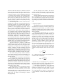
The PWM duty ratio is determined by the formula
D=
N +1
, N = 0, … ,254
256
C. Sense Circuits
The output sense circuits measure motor winding
voltages and currents. The winding voltage zero crossings are detected and input to the DSP as comparator
output waveforms, and the currents are measured as
scaled analog voltages (3.5 A/V). These voltages are
input to an Analog Devices AD7811 ADC. The ADC
outputs are sent to the serial port 0 (SPORT0) input of
the DSP. The SPORT0 output simultaneously sets the
channel for the next A/D sample acquisition.
These measurements make it possible to implement
many different firmware-level control schemes, including winding-sensed (sensorless) control. The DSP reads
digitized motor winding voltages and currents from the
motor and performs appropriate firmware-level signal
processing. The DSP uses this feedback to compute the
appropriate quantities (torque or speed), and then compares the acquired value to the commanded value. The
error difference is processed by a firmware-level controller to achieve the desired dynamic loop response. The
output quantities of the controller are the duty ratios, D,
that are sent to the dual PWM generator via DSP
SPORT1.
To sense winding-voltage zero crossings, low-cost
LM358 differential amplifiers low-pass filter the switching noise from the winding voltages before driving
where N is the 8-bit magnitude that comes from the DSP.
The end of a PWM cycle interrupts the DSP, which
then computes new values of D for the A and B PWM
signals. The composite 18-bit PWM data stream is
shifted out of the DSP before the end of the PWM cycle,
so that when it occurs, the updated values of D are
loaded into the shift registers at the 255 count (reload
state), starting the new cycle.
For development and testing, it is hard to view a
PWM waveform as a duty ratio changing in time. To
recreate an approximate waveform, the PWM outputs
are low-pass filtered with resistor-capacitor combinations and are available at test points on the SMC3. They
normally appear as approximate (obviously sampled)
sine magnitudes (haversines) that are in quadrature with
each other. An example will be shown in Section V.
B. Power Drivers
The SMC3 contains two identical full H-bridge
power drivers, one for each phase-winding. This section
will consider only the winding A driver; the B driver is
identical to it.
The full H-bridge driver provides bipolar drive to
the motor windings, connected between the positive and
3