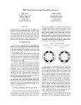
1
ASDIP STRUCTURAL SOFTWARE
ASDIP 4
User’s Manual
Copyright © ASDIP Structural Software
1
Table of Contents
Chapter 1 – The Basics
Introduction……..………………………………………………………………. 1-1
Definitions ……………………………………………………………………… 1-1
Features ……………………………………………………………………….. 1-2
Hardware Requirements ……………………………………………………... 1-3
Installation ………………...…………………………………………………… 1-4
Running ASDIP 4 …………………….……………………………………….. 1-4
Disclaimer ……………………………………………………………………... 1-4
Chapter 2 – Operating the Program
The Main Menu ……………………………………………………………….. 2-1
The Tool Bar ……………………………………………………………..…. 2-12
Chapter 3 – The Modules …………………………………………………………... 3-1
Chapter 4 – Concrete Beam Deflections
Input Data ……………………………………………………………………... 4-1
Example ……………………………………………………………….………. 4-1
Output ………………………………………………………………………….. 4-3
Chapter 5 – Corbels and Beam Ledges
Input Data ……………………………………………………………………... 5-1
Example ……………………………………………………………….………. 5-2
Output ………………………………………………………………………….. 5-3
Chapter 6 – Concrete Deep Beams
Input Data ……………………………………………………………………... 6-2
Example ……………………………………………………………….………. 6-2
Output ………………………………………………………………………….. 6-4
Copyright © ASDIP Structural Software
2
Chapter 7 – Concrete Circular Columns
Input Data ……………………………………………………………………… 7-2
Example ……………………………………………………………….…...….. 7-3
Output ………………………………………………………………………….. 7-4
Chapter 8 – Concrete Rectangular Columns
Input Data ……………………………………………………………………... 8-1
Example ……………………………………………………………….….....… 8-2
Output ………………………………………………………………………..… 8-3
Chapter 9 – Concrete Shear Walls
Input Data …………………………………………………………………..…. 9-2
Example ……………………………………………………………….….....… 9-2
Output ………………………………………………………………………..… 9-4
Chapter 10 – Lateral Load Distribution
Input Data ……………………………………………………………………. 10-1
Example ……………………………………………………………….…...… 10-2
Output ………………………………………………………………………… 10-4
Chapter 11 – Masonry Walls
Input Data ……………………………………………………………………. 11-2
Example ……………………………………………………………….…...… 11-2
Output ………………………………………………………………………… 11-3
Chapter 12 – Beams with Web Openings
Input Data ……………………………………………………………………. 12-1
Example ……………………………………………………………….…...… 12-2
Output ………………………………………………………………………… 12-3
Chapter 13 – Loads on Pile Groups
Input Data ……………………………………………………………………. 13-1
Example ……………………………………………………………….…...… 13-3
Output ………………………………………………………………………… 13-4
Copyright © ASDIP Structural Software
3
Chapter 14 – Vibration of Joist Floors
Input Data ……………………………………………………………………. 14-1
Example ……………………………………………………………….…...… 14-1
Output ………………………………………………………………………… 14-3
Chapter 15 – Concrete Beams
Input Data ……………………………………………………………………. 15-1
Example ……………………………………………………………….…...… 15-2
Output ………………………………………………………………………… 15-4
Chapter 16 – Seismic Design of Shear Walls
Input Data ……………………………………………………………………. 16-1
Example ……………………………………………………………….…...… 16-2
Output ………………………………………………………………………… 16-4
Appendix A – References
Copyright © ASDIP Structural Software
Chapter 1
The Basics
INTRODUCTION
Frequently, the design process involves an iterative procedure of selecting possible
proportions for structural elements, and then checking to determine whether the first
solution is the best one. This repetitive and tedious procedure may become time and
effort consuming in any structural design office.
ASDIP 4 is a collection of stand-alone programs that carefully integrate building code
provisions with proven design and analysis techniques to perform many of the
repetitive and sometimes cumbersome calculations most commonly used in
structural engineering.
ASDIP 4 is an integrated, interactive system that combines the flexibility of a fill-inthe-blanks format with the power of the Windows environment to effortlessly develop
either an optimal design or a quick investigation.
The fill-in-the-blanks format gives the user the opportunity to change the value of any
variable and immediately obtain the result without re-entering all the input data. In
addition, the designer may perform "what if ...?" analysis, this is, appreciate the
relationship between the variables involved in a specific problem and optimize the
design with minimum effort.
All the programs have been assembled to help the designer obtain specific results
from procedures common to structural concrete, steel and masonry design.
However, they cannot replace the judgment of an experienced engineer who must
select the structural types and appropriate loads, and interpret the results obtained
adequately from the analysis of structural systems.
Copyright © ASDIP Structural Software
1-2
DEFINITIONS
Module is a program that forms part of ASDIP 4, so we will use the terms
program, module, application synonymously throughout this Manual.
Template is a page in every module dedicated to show, in a neat and condensed
form, the input data and a selection of the most important information.
Report is a pre-formatted page in every module that shows a detailed, well
organized, ready to print information about your design.
All the modules have been protected to avoid accidental changes in formulas, with
the exception of those fields assigned for the required input data, which appear
highlighted in the programs for easier identification. The input data may be entered
directly on the templates, or using the input dialog boxes.
The input dialog boxes may be invoked by either double-clicking on the input
data fields or using the pull-down menus.
All the programs have been written to work with any of the following three unit
systems:
•
US - English units, customarily used in the United States (in, ft, kip, ksi).
•
SI - The International Standard system of units (cm, m, N, MPa).
•
ME - Metric units, used in Europe and Latin America (cm, m, Tn, kg/cm2).
All the programs are able to generate graphs as a design tool to help the user
visualize the design in an easier and faster way. The ASDIP 4 context-sensitive
Help System may be invoked anytime and anywhere by just pressing the [F1] key
to obtain information on any command with the extensive on-line documentation.
Copyright © ASDIP Structural Software
1-3
FEATURES
•
Stand-alone programs which run in Windows XP/Vista/7. No additional
software required.
•
Fill-in-the-blanks format with in-field editing.
•
Highlighted input fields for easier identification of fields assigned for data entry.
•
Personalized programs with your company name on screen and printouts.
•
Multi-level context-sensitive help system to guide you through the use of the
programs. Simply press [F1] to obtain information on any command.
•
Documented calculations step-by-step on screen. This allows the designer to
follow the procedure and check any result.
•
Customized command tree with selective menu commands in each particular
program for easier use.
•
Secured fields to avoid accidental changes in formulas.
•
Much smaller data file than the program itself. When saving several sets of
data from the same program, it results in a 5 to 10 times disk space reduction.
•
Combined text-with-values output messages updated with each new change.
•
Three different unit systems available:
US units (in, ft, Kip, ksi)
SI units (cm, m, N, MPa)
ME units (cm, m, Tn, Kg/cm2)
•
Printouts with ASCII characters and solid lines for excellent quality outputs.
•
Complete built-in steel sections database.
•
Graphics printing without leaving the program. This way you may include
graphs in your set of calculations.
•
Fast performance. Significant improvements due to compiled formulas, minimal
recalculation, and automatic coprocessor support.
•
Mouse support for quick movement of the field pointer through the screen.
•
Lenient hardware requirements.
•
Selective printing options.
•
Exclusive ASDIP 4 Input Validation feature to avoid invalid data or erroneous
input format, such as negative values for materials’ properties, etc.
Copyright © ASDIP Structural Software
1-4
HARDWARE REQUIREMENTS
To use ASDIP 4, a personal computer with the following minimum hardware and
software configuration is needed:
•
Microsoft Windows XP/Vista/7 32-bit only. For 64-bit, XP-mode is required.
•
16 MB installed RAM minimum.
•
Hard disk with at least 25 MB of free space.
•
A mouse or other pointing device supported by Windows.
INSTALLATION
1. Download the demo from our web site and follow the instructions.
2. When you order the software the license instruction will be emailed to you.
RUNNING ASDIP
Once ASDIP 4 is installed, it is ready to run. Select ASDIP from the Start |
Programs menu or simply double-click on the icon. ASDIP 4 will run in demo mode
until you validate your license. To do so follow the instructions emailed to you the
same day you place the order.
DISCLAIMER
A great effort has gone into the development of ASDIP. Although all the programs
have been thoroughly tested and used to assure the correctness of analytical
solutions, the structural engineer of record is responsible for modeling the
structure, inputting data, and applying engineering judgement to evaluate the
output. ASDIP Structural Software disclaims all responsibility for damages of any
kind resulting from the use of the information contained herein, or generated by
this document, and the accompanying computer software.
Copyright © ASDIP Structural Software
Chapter 2
Operating ASDIP
THE MAIN MENU
ASDIP 4 uses pull-down menus to access commands that allow, among other tasks,
the manipulation of files, inputting of data, changing the look of the program window,
setting preferences, running the program, showing the graphs, and printing the
results.
The File Menu
The File menu is used to transfer information between
files, such as open, close and save data files, print
results, and exit the program.
File | Open
Allows you to load an ASDIP 4 program. The dialog box
that appears shows you a listing of all the options
representing the programs that compose ASDIP 4.
Choose the program you want to open from the dialog box. A brief description of your
selection is displayed at the bottom of the list of modules. Click Open to confirm your
selection.
When you start ASDIP 4, it starts without any module window (a blank screen). Load
the program you want to work on using this command. As an alternative, use the
Open icon from the tool bar for an easier and direct selection.
ASDIP allows up to 5 open modules at a time. To toggle between open modules,
select from the list at the pull down Navigate Menu.
Copyright © ASDIP Structural Software
2-2
Figure 1. - The FILE OPEN dialog box
File | Close
This command closes the program contained in the active window. If you have
made any changes, you may save your input data using File | Save Data from the
menu bar before closing. If you have only one open module and select this
command, then ASDIP 4 will not allow you close your only module and will display
a text box instead.
File | Save Data
Saves the changes made to the current data file under any filename. If a file of the
same name exists, ASDIP 4 will ask you if you want to overwrite that file. This
feature allows you to save several versions of data for the same program, not the
program itself, which results in significant disk space reduction. When you choose
the Save Data command, the dialog box of Figure 2 shows up.
•
All data files corresponding to the calling module are displayed in the FILE
NAME list box. To save the data file in another drive or directory, use the DRIVES
drop-down list or the DIRECTORIES list box, respectively.
•
In the FILE NAME text box, type a new filename. You do not have to supply a file
extension; since it will be appended to the specified file.
•
Press ENTER or choose the OK button.
Copyright © ASDIP Structural Software
2-3
Figure 2. - The SAVE DATA dialog box.
File | Retrieve Data
Allows you to load an existing ASDIP 4 data file. This command invokes a dialog box
similar to the one shown in Figure 2.
File | Clear Data
Clears the contents of all the input data cells of the active module.
File | Print
You may obtain a predefined and preformatted printout of your project by using
File | Print from the menu bar. ASDIP 4 may print out the TEMPLATE and the
REPORT pages, as well as the generated graphs. Alternatively, use the print icon
in the tool bar. Figure 3 shows the dialog box related to this command.
Figure 3. - The PRINT dialog box.
Copyright © ASDIP Structural Software
2-4
File | Printer Setup
This command allows you to select the active printer as specified in the Control
Panel (Refer to your Microsoft Windows manual on using the Control Panel).
File | Exit
This closes all open files and exits the program. ASDIP 4 does not prompt you to
save your data. If a module has unsaved changes, this information will be lost.
Unlike File | Close, File | Exit closes all windows in your application and shuts
down ASDIP 4.
The Edit Menu
The Edit menu includes commands to manipulate input
data, such as Copy, Paste, and Clear. These commands
have effect only on the data entry cells, which appear
highlighted on the screen.
Edit | Copy
Stores the contents of a range of input cells in the clipboard. This command is very
useful to enter repetitive data in tabular form directly on the screen.
Edit | Paste
Copies data previously stored with Edit | Copy to the module page just where the
cellpointer is located. The format of the target range is not altered. ASDIP does not
use the clipboard to perform this operation, but a .TXT file internally generated with
Edit | Copy.
Edit | Clear
Erases the contents of a range of input cells.
The Input Menu
The Input menu includes commands that enable you to input
labels, enter material properties, and define geometry,
reinforcement, and load data. Alternatively, ASDIP 4 allows
you enter data directly on the template, if you do not want to
Copyright © ASDIP Structural Software
2-5
use the corresponding dialog boxes. However, it is recommended to use the dialog
boxes in order to validate and exert better control of your input data.
TIP: Double-click on an input cell to show the corresponding dialog box.
IMPORTANT: If the Options | Recalculation command has been set MANUAL, you
must press the [F9] key to update the program calculations and output. Otherwise,
the results will not be correct. When the data changes, ASDIP shows a "CALC"
indicator on the status bar to remind you that the formulas need to be recalculated
in order to obtain the correct result.
Input | Labels
To keep track of data and output, ASDIP allows you to specify the project name, a
brief description, and the engineer’s name. This information is printed with the
output and is intended to help you organize your data.
•
From the Input menu, select Labels…. The dialog box of Figure 4 appears.
Figure 4. - The LABELS dialog box.
•
Enter the labels in the corresponding text boxes.
•
Press ENTER or choose the OK button.
Input | Materials
Allows you to input the materials’ properties, such as concrete and steel strength.
When this command is selected, a dialog box appears, as shown in Figure 5. This
dialog box may vary depending on the program being used.
Copyright © ASDIP Structural Software
2-6
Figure 5. - The MATERIALS dialog box
•
Enter the concrete strength f’c in the corresponding text box (if different than
the current value).
•
Enter the steel yield strength fy in the corresponding text box (if different than
the current value).
•
Press ENTER or choose the OK button.
Input | Geometry
Allows you to define the structure’s geometry. When this command is selected, a
dialog box appears, depending on the program being used. This dialog box is
shown separately for each program in the next chapters.
Input | Reinforcement
Allows you to input reinforcement data in concrete structures, such as bar size and
spacing, number of stirrups, clear cover, etc. When this command is selected, a
dialog box appears, depending on the program being used. This dialog box is
shown separately for each program in the next chapters.
Input | Loads
Allows you to input the applied loads, either service or factored, such as vertical
and horizontal, concentrated, or distributed. When this command is selected, a
dialog box appears, depending on the program being used. This dialog box is
shown separately for each program in the next chapters.
The Design Menu
The Design menu contains commands that enable you to select
the steel section to be analyzed, execute the solver portion of
ASDIP 4, define the unit system, and work with the graphic output.
Copyright © ASDIP Structural Software
2-7
Design | Select
This command allows you to access the built-in steel sections database provided
with ASDIP 4 and select the desired section to be analyzed.
•
Choose Select… from the Design menu. The dialog box in Figure 6 shows up.
•
From the Section drop-down list box select the section designation. ASDIP 4
shows in the adjacent window the properties of the specified selection..
•
Press ENTER or choose the Select button.
Figure 6. - The SELECT dialog box
Design | Solve
This command executes the ASDIP’s solver engine used by some of the
programs. This command is intended to provide the user with the tool to “run” the
solver at any time. Most of the modules are solved internally and, therefore, do not
have this command.
Design | Units
ASDIP 4 allows you to work with any of the following unit systems:
US - Customarily used in the United States (kip, ft, in, ksi)
SI - The International system of units (KN, m, cm, MPa)
ME - Mostly used in Europe and Latin America (Tn, m, cm, Kg/cm2)
Copyright © ASDIP Structural Software
2-8
•
Select Units from the Design menu. The dialog box in Figure 7 appears.
•
Choose an option from the ratio buttons, which are mutually exclusive.
•
Press ENTER or choose the OK button.
Figure 7. - The UNITS dialog box
Design | Graph
Contains a cascading menu with commands that allow you to work with the output
graphs generated by ASDIP 4.
8View
Choose this option to display a graph directly onto the screen.
Figure 8. - The GRAPH/VIEW dialog box.
•
From the Design menu select Graph. From the cascading menu select
View. A dialog box appears similar to the one shown in Figure 8.
•
Choose an option from the ratio buttons, which are mutually exclusive.
•
Press ENTER or choose the OK button.
Copyright © ASDIP Structural Software
2-9
8Print
Choose this option to print a graph to the active printer.
•
From the Design menu select Graph. From the cascading menu select
Print. A dialog box appears similar to the one shown in Figure 8.
•
Choose an option from the ratio buttons, which are mutually exclusive.
•
Press ENTER or choose the OK button.
The Options Menu
The Options menu contains commands that enable you to
customize ASDIP 4 according to your personal preferences and
needs.
Options | Data Folder
Allows you to specify the folder that ASDIP uses to save and retrieve data files. To
set a default data folder use the Settings | Data Folder command at startup.
•
Choose Data Folder from the Options menu. The dialog box of Figure 9
appears.
Figure 9. - The DATA FOLDER dialog box
•
Enter a folder in the text box and press ENTER.
Options | Recalculation
Allows you to specify the way ASDIP 4 recalculates the module. You set the
method: either AUTOMATIC or MANUAL.
Copyright © ASDIP Structural Software
2-10
In automatic mode, ASDIP 4 recalculates internally all formulas when you make a
change to the contents of a field. In manual mode, it recalculates only when you
press the [F9] key or the corresponding icon in the tool bar. The default is
AUTOMATIC. Note that sometimes is useful to set the recalculation mode to MANUAL,
for example to fill a table of data directly on the template.
Figure 10.- The RECALCULATION settings.
Important: Unlike Automatic mode, in Manual mode you are allowed to enter data
directly on the template.
The Navigate Menu
The Navigate menu choices let you move between
pages in your application, and select the active module
from the open modules list.
ASDIP 4 allows up to five open modules at a time. This
menu command contains the list of the open modules,
where you can select your active module. ASDIP 4 shows a check mark to indicate
the current active module. You may switch to another open module by left-clicking on
the desired selection.
The Help Menu
Even though ASDIP 4 has been designed to be a userfriendly package and is actually very easy to use, this menu
includes several options that guide you throughout the
program with extensive on-line documentation.
Copyright © ASDIP Structural Software
2-11
THE TOOL BAR
ASDIP uses icons to quickly access point-and-click visual interface elements that
perform some of the most common tasks within ASDIP. As a reference, the
meaning of every icon appears in the status bar at the top of the main window.
Opens a module. This is similar to File | Open
Closes the current module’s window. This is similar to File | Close
Loads an existing data file. This is similar to File | Retrieve Data
Saves the data in a file. This is similar to File | Save Data
Stores the contents of a range in the clipboard. This is similar to Edit | Copy
Retrieves the contents of the clipboard. This is similar to Edit | Paste
Prints the module’s template. This is similar to File | Print
Displays a graph onto the screen. This is similar to Design | Graph | View
Recalculates the formulas. This is similar to pressing the [F9] key
Displays the on-line documentation. This is similar to Help | Contents
Copyright © ASDIP Structural Software
Chapter 3
The Modules
List of programs that compose ASDIP:
- Analysis of deflections in concrete beams and one-way slabs.
- Design of concrete corbels and beam ledges.
- Design of concrete deep beams.
- Design of circular concrete columns.
- Design of rectangular concrete columns.
- Design of any-shaped concrete shear-walls.
- Analysis of lateral-load distribution.
- Design of tall slender masonry walls.
- Design of steel beams with web openings.
- Analysis of loads on pile foundations.
- Analysis of vibrations in steel joist / concrete slab floors.
- Design of concrete beams under combined loading.
- Seismic design of shear walls (ACI-318, Chapter 21).
.
Copyright © ASDIP Structural Software
Chapter 4
Concrete Beam Deflections
Serviceability of a structure is determined by its deflection, cracking, extend of
corrosion, and surface deterioration. Excessive deflection of a beam or slab can
damage a partition below, and excessive deflection of a lintel beam above a window
opening can crack the glass panes.
This program computes the maximum deflection of a simply supported doublereinforced concrete rectangular or T beam under the action of service loads, taking
into account the immediate and the long-term effects, according to ACI design
criteria. In addition, continuous beams or one-way slabs may also be modeled by
entering the corresponding end moments.
INPUT DATA
The required input data consists of the materials’ properties and beam dimensions.
In addition, the service dead and live loads (a distributed load and two end moments)
are required. Figure 1 shows schematically the required input data.
Figure 1. - Required input data.
EXAMPLE
Find the maximum deflection of a uniformly loaded continuous beam with four spans
of 36 ft., a width of 14 in. and a total depth of 21-in. supporting a 4" slab. The steel
area is 4.00 in2 at a depth of 18.25 in. The beam is subjected to a service dead load
Copyright © ASDIP Structural Software
4-2
Concrete Beam Deflections
of 700 plf including its self-weight and a live load of 1200 plf. Use f'c = 4 ksi and fy =
60 ksi. Assume that 50% of the live load is continuously applied.
Figure 2. - Example problem data.
From the Input menu select Geometry and enter the required information in the
GEOMETRY dialog box, as shown in Figure 3.
Figure 3. - The GEOMETRY dialog box.
Copyright © ASDIP Structural Software
4-3
Concrete Beam Deflections
From the Input menu select Loads to enter the applied service loads in the LOADS
dialog box, as shown in Figure 4.
Figure 4. - The LOADS dialog box.
The program computes the section’s properties in the pre-cracking and post-cracking
stages and calculates the effective moment of inertia based on the Branson
approach. The maximum deflection is computed as the sum of the instantaneous
deflection and the long-term deflection in accordance with the ACI procedure. It is
then compared with maximum values allowed, depending on the type of structure.
OUTPUT
Figure 5 shows the template related to this program with the example problem data.
In this example, the code deflection criterion is met by conditions A and B only.
Therefore, the continuous beam is limited to floors or roofs not supporting or attached
to nonstructural elements such as partitions.
(Note: this problem is solved in Ref. 3 page 273, Example 8.4).
This program generates the beam’s bending moment diagram for the dead and live
loads. Select Graph and View from the Design menu to display the graph, as shown
in Figure 6.
Copyright © ASDIP Structural Software
4-4
Concrete Beam Deflections
Figure 5. - Template of the program.
Figure 6. - Graphical view of the moment diagram
Copyright © ASDIP Structural Software
Chapter 5
Corbels and Beam Ledges
Brackets or corbels are short-haunched cantilevers that project from the inner part of
columns to support heavy concentrated loads or beam reactions. Its design has
become increasingly important with the extended use of precast and prestressed
concrete members and larger spans, resulting in heavier shear loads at supports. A
beam ledge is a cantilever that project from a concrete column to support
perpendicular precast beams.
The program performs the design of a reinforced concrete corbel or beam ledge
subjected to vertical and horizontal combined factored loads, based on the Strut
Theory approach and the ACI Ultimate Strength Design Method. The program
designs the reinforcing steel as well as the bearing plate.
INPUT DATA
The required input data consists of the materials’ properties, the corbel o beam ledge
dimensions, the applied loads, and its position. For the reinforcement design, the bar
size and spacing for the main tension steel and the horizontal stirrups are required.
Figure 1 shows the required input data.
Figure 1. - Required input data.
Copyright © ASDIP Structural Software
5-2
Corbels and Beam Ledges
EXAMPLE
As an example, design the corbel to project from a 14” square column supporting a
factored vertical load of 86.4 kips acting at a distance of 3.0 in. from the face of the
column, as shown below. Use f’c=4000 psi and fy=60 ksi.
Figure 2. - Example problem data.
From the Input menu select Geometry to enter the dimensions in the GEOMETRY
dialog box, as shown in Figure 3.
Figure 3. - The GEOMETRY dialog box.
Copyright © ASDIP Structural Software
5-3
Corbels and Beam Ledges
From the Input menu select Reinforcement to enter the bar size information in the
REINFORCEMENT dialog box, as shown in Figure 4.
Figure 4. - The REINFORCEMENT dialog box.
From the Input menu select Loads to enter the applied loads in the LOADS dialog
box, as shown in Figure 5.
Figure 5. - The LOADS dialog box.
OUTPUT
Once the input data is entered, the program performs the computations and checks
the adequacy of the design. The output consists of three non-dimensional numbers
indicating the limitations in shear capacity and the steel area provided. All these
ratios should be no greater than 1.0.
In addition, the program computes the required bearing plate area under the load to
avoid concrete bearing failure.
Copyright © ASDIP Structural Software
5-4
Corbels and Beam Ledges
Figure 6. - Template of this program.
Figure 7. – Graph generated by the program.
Copyright © ASDIP Structural Software
Chapter 6
Concrete Deep Beams
Deep beams are structural elements loaded as beams in which a significant amount
of the load is transferred to the supports by a compression thrust joining the load and
the reaction. As a result, the strain distribution is no longer considered linear, and the
shear deformations become significant when compared to pure flexure. Floor slabs
under horizontal load, short span beams carrying heavy loads, and transfer girders
are examples of deep beams.
This program performs the design of a simply supported reinforced concrete
rectangular deep beam subjected to a uniformly distributed load and two
concentrated loads applied on its top face.
The program is based on the ACI Ultimate Strength Design Method and applies to
those flexural members having a clear span to height ratio of less than 4. The flexural
reinforcement is designed taking into account the reduced lever arm due to the nonlinearity of the strains’ distribution.
Figure 1. - Required input data.
Copyright © ASDIP Structural Software
6-2
Concrete Deep Beams
INPUT DATA
The required input data includes the materials’ properties and member dimensions,
as well as the applied factored loads, not including self-weight. For the shear
reinforcement design, the vertical and horizontal bar size and spacing is needed.
Figure 1 schematically shows the required input data.
EXAMPLE
Consider the simply supported beam having a clear span of 10 ft subject to a
distributed factored live load of 146.2 k/ft on top. The beam height is 72 in. and its
thickness is 20 in. as shown in Figure 2. Design the reinforcement.
Figure 2. - Example data.
From the Input menu select Geometry to enter the dimensions in the GEOMETRY
dialog box, as shown in Figure 3.
From the Input menu select Reinforcement to enter the bar size information in the
REINFORCEMENT dialog box, as shown in Figure 4.
Copyright © ASDIP Structural Software
6-3
Concrete Deep Beams
Figure 3. - The GEOMETRY dialog box.
Figure 4. - The REINFORCEMENT dialog box.
From the Input menu select Loads to enter the applied loads in the LOADS dialog
box, as shown in Figure 5.
Figure 5. - The LOADS dialog box.
Copyright © ASDIP Structural Software
6-4
Concrete Deep Beams
OUTPUT
Once the input data is entered, the program automatically verifies the adequacy of
the design. The output consists basically of three messages indicating the adequacy
of the spacing of the proposed reinforcement, and five non-dimensional numbers
checking the limitations in section capacity and bar sizes suggested by the building
code. All these ratios should not be greater than 1.0.
Figure 6 shows the template related to this program with data from the example
problem.
Figure 6. - Template of the program.
By choosing the Graph and View options from the Design menu, a graphic view of
the deep beam is displayed showing important data such as the steel reinforcement,
member dimensions, and material properties, as shown in Figure 7
Copyright © ASDIP Structural Software
6-5
Concrete Deep Beams
Figure 7. - Schematic view of the deep beam.
A detailed report may be obtained by clicking on the corresponding icon on the tool
bar or by selecting Navigate | Go to Report from the menu.
Copyright © ASDIP Structural Software
Chapter 7
Concrete Circular Columns
Columns are structural compression members which transmit loads from the upper
floors to the lower levels and then to the soil through the foundations. Since columns
are compression elements, failure of one column in a critical location can cause the
progressive collapse of adjoining floors, and in turn, even the collapse of the entire
structure.
Although tied columns are most commonly used because of the lower construction
costs, spirally bound circular columns are also used where increased ductility is
needed, such as in earthquake zones. The ability of a spirally reinforced column to
sustain the maximum load at excessive deformation prevents the complete collapse
of the structure before total redistribution of moments and stresses is complete.
Failure in columns could occur as a result of material failure or by loss of lateral
structural stability. If a column fails due to material failure, it is classified as a short
column, as opposed to the slender column whose failure is by buckling.
This program generates the axial load vs. bending moment interaction diagram of an
unconfined circular concrete column, with uniform arrangement of non-prestressed
reinforcing bars, taking into account the slenderness effects.
The program is based on the equilibrium of forces and compatibility of deformations.
The following assumptions have been made:
1. Stresses in concrete and steel are directly proportional to the distance from the
neutral axis.
2. Maximum useable strain at extreme concrete compression fiber is 0.003 in/in.
3. The Hognestad concrete stress-strain relationship is used.
4. For reinforcing steel, the elasto-plastic model is used, taking into account the
strain hardening effect.
5. Tensile strength of concrete is neglected.
Copyright © ASDIP Structural Software
7-2
Circular Concrete Columns
The column section has been divided in 80 layers of the same thickness. The strain,
and therefore the stress, is assumed to be constant in all the thickness of each
segment and equal to that present at its mid-depth.
The interaction diagram is generated by defining several positions of the neutral axis
and checking the external forces (P and M) for each condition that satisfies the
equilibrium of forces. The program takes into account the correction of concrete
forces for the area in the compression block displaced by vertical bars.
The program generates the diagram with the actual curve stress-strain of the
concrete rather than using the equivalent rectangular stress distribution. This is in
recognition of the fact that the Whitney's stress block, although simpler, is not
correctly applicable to non-rectangular compression areas, since the centroids of the
actual and idealized blocks do not coincide.
INPUT DATA
The required input data includes the materials’ properties, the applied factored loads
and the geometric characteristics of the section such as the column diameter and
number and size of reinforcing bars, as shown in Figure 1.
Figure 1. - Required input data.
The program also allows optional input where clear cover other than 1.5 inches, or
where other than minimum size #3 or #4 circular ties or spirals are desirable. Thus,
the results are directly applicable for precast columns with small cover or where
severe exposure requires more concrete protection for reinforcement.
Copyright © ASDIP Structural Software
7-3
Circular Concrete Columns
The actual layout of vertical bars has been conservatively selected as least effective
overall to produce the lowest value in moment for steel areas. Figure 2 shows the
actual bar patterns used where N<=8 bars, as opposed to the equivalent thin cylinder
used to represent the sum of actual bar areas where N>8.
Figure 2. - Arrangement of vertical bars.
EXAMPLE
As an example, consider an 18" diam, 12-ft long spirally reinforced round column
subject to an axial load of 165 k and a bending moment of 110 k-ft. It is reinforced
with seven #8 vertical bars equally spaced as shown in Figure 3. Generate the
interaction diagram and find out if the section is adequate. f'c = 4 ksi and fy = 60 ksi.
Figure 3.- Example data.
Copyright © ASDIP Structural Software
7-4
Circular Concrete Columns
From the Input menu select Geometry to enter the dimensions in the GEOMETRY
dialog box, as shown in Figure 4.
Figure 4.- The GEOMETRY dialog box.
From the Input menu select Loads to enter the applied loads in the LOADS dialog
box, as shown in Figure 5.
Figure 5.- The LOADS dialog box.
Copyright © ASDIP Structural Software
7-5
Circular Concrete Columns
OUTPUT
Once the input data has been completed, choosing the Solve option from the
Design menu can generate the tabulation of the interaction diagram. Figure 6 shows
the program’s template.
Figure 6.- Template of the program.
Copyright © ASDIP Structural Software
Circular Concrete Columns
7-6
To determine a specific point of interest not tabulated in the interaction diagram,
enter a “k-Factor” value on the template, where the corresponding axial load and
bending moment are calculated for a specified neutral axis position.
The program applies the appropriate ACI under-strength Phi factor to the applied
loads in order to be compared with the nominal strength of the section.
A graphic view of the interaction diagram and the applied loads may be displayed by
choosing the Graph and View options from the Design menu, as shown in Figure 7.
Figure 7.- Schematic view of the interaction diagram.
In this example, the section is adequate to carry the imposed loads, since the point
representing the acting loads appears into the useable area delimited by the
interaction diagram and the coordinate axes.
A detailed report may be obtained by clicking on the corresponding icon on the tool
bar or by selecting Navigate | Go to Report from the menu.
Copyright © ASDIP Structural Software
Chapter 8
Concrete Rectangular Columns
This program generates the Pn-Mn nominal interaction diagram for a rectangular
concrete column with up to five layers of reinforcing steel, and calculates the capacity
of a member when subjected to bending moment and axial load. The slenderness
effect or secondary moments owing to the lateral deflection response under load are
also considered.
The following assumptions have been made:
1. Strains in reinforcement or concrete are directly proportional to the distance from
the neutral axis.
2. Maximum useable strain at extreme concrete compression fiber is 0.003 in/in.
3. The Whitney rectangular stress distribution for concrete is used.
4. The elasto-plastic stress-strain relationship for reinforcing steel is used.
5. Tensile strength of concrete is neglected.
INPUT DATA
The input data required by the program includes the geometric characteristics of the
section, the materials’ properties and the applied combined ultimate loads, as shown
in Figure 1.
Figure 1. - Required input data.
Copyright © ASDIP Structural Software
8-2
Rectangular Concrete Columns
EXAMPLE
As an example, consider the section shown in Figure 2 subjected to a bending
moment of 200 k-ft and an axial load of 450 kips. f'c = 3000 psi, fy = 50000 psi. Find
out if the section is adequate.
Figure 2.- Example problem data.
From the Input menu select Geometry to enter the dimensions and reinforcement
information in the GEOMETRY dialog box, as shown in Figure 3.
Figure 3. - The GEOMETRY dialog box.
Copyright © ASDIP Structural Software
8-3
Rectangular Concrete Columns
From the Input menu select Loads to enter the applied factored loads in the LOADS
dialog box, as shown in Figure 4.
Figure 4. - The LOADS dialog box.
OUTPUT
Once the input data has been completed, choosing the Solve option from the
Design menu can generate the tabulation of the interaction diagram. Figure 5 shows
the program’s template.
The program applies the appropriate ACI under-strength Phi factor to the applied
loads in order to be compared with the nominal strength of the section, and estimates
a capacity ratio based on the position of these loads in the interaction diagram. This
ratio should not be greater than 100%. To determine a specific point of interest in the
interaction diagram, enter a “k-Factor” value in the template, where the
corresponding moment is calculated for a specified axial load.
In this example, the section is adequate to carry the imposed loads, since the point
representing the acting loads appears into the useable area delimited by the
interaction diagram and the coordinate axes.
A graphic view of the interaction diagram and the applied loads may be displayed by
choosing the Graph and View options from the Design menu, as shown in Figure 6.
Copyright © ASDIP Structural Software
8-4
Rectangular Concrete Columns
Figure 5.- Template of the program.
Figure 6.- Graphic view of the interaction diagram.
Copyright © ASDIP Structural Software
Chapter 9
Concrete Shear Walls
This program generates the Pn-Mn nominal-capacity interaction diagram for anyshape concrete section with any arrangement of non-prestressed reinforcing steel.
The program is entirely based on the equilibrium of forces and compatibility of
deformations. The following assumptions have been made:
1. Strains are directly proportional to the distance from the neutral axis.
2. Plane sections before bending remain plane after bending.
3. For concrete, the Hognestad stress distribution is used.
4. For reinforcing steel, the elasto-plastic model is used, taking into account the
strain hardening effect.
The section is divided in horizontal layers, or segments of the same thickness, whose
number is defined by the user. The strain, and therefore the stress, is assumed to be
constant throughout the thickness of each segment, and equal to that present at its
mid-depth.
The interaction diagram is generated by first defining the position of the neutral axis.
The strain and stress in each segment are then computed, and the equilibrium of
forces checked. This way, one point in the interaction diagram is found. The
procedure is repeated changing the neutral axis to another position, and so on, until
the diagram is completed.
Of course, the greater the number of segments, the more precise the results
obtained. The designer’s judgement plays an important role in deciding how accurate
are the results obtained. The maximum number of segments allowed is 100.
Copyright © ASDIP Structural Software
9-2
Any-shaped Concrete Shear Walls
INPUT DATA
The data required includes the materials’ properties, the ultimate concrete strain, the
total section length, and the number of segments in which that section length will be
divided. In addition, the program requires the width and steel area of each defined
segment. The required input data is presented schematically in Figure 1.
Figure 1.- Required input data.
EXAMPLE
As an example, consider the channel section shown below reinforced as indicated,
and subjected to a moment about its weak principal axis causing tension at the web
and compression at the ends of the flanges. Find the capacity interaction diagram of
the section.
From the Input menu select Geometry to enter the dimensions in the GEOMETRY
dialog box, as shown in Figure 3.
Copyright © ASDIP Structural Software
9-3
Any-shaped Concrete Shear Walls
Segment
b
As
(in)
(in²)
───────────────────────
1
28
0.28
2
28
0.28
3
28
0.28
4
28
0.28
5
28
0.28
6
28
0.28
7
28
0.28
8
28
0.28
9
28
0.28
10
28
0.28
11
28
0.28
12
28
0.28
13
28
0.28
14
28
0.28
15
28
0.28
16
28
0.28
17
28
0.28
18
28
0.28
19
28
0.28
20
28
0.28
21
28
0.28
22
28
0.28
23
28
0.28
24
28
0.28
25
28
0.28
26
28
0.28
27
28
0.28
28
28
0.28
29
28
0.28
30
216
0.28
31
216
0.28
32
216
0.28
33
216
14.14
34
216
0
35
216
0
36
216
0
Figure 2. - Example data.
Figure 3. - The GEOMETRY dialog box.
Once the number of segments has been defined, enter the width and reinforcement
of each individual segment in the REINFORCEMENT dialog box as shown in Figure 4,
or, if you prefer, directly in the table provided below the template. TIP: Take
advantage of the ASDIP spreadsheet-like format and use the Copy and Paste
commands from the Edit menu to enter the numbers onto this table.
Copyright © ASDIP Structural Software
Any-shaped Concrete Shear Walls
9-4
Figure 4. – The REINFORCEMENT dialog box.
From the Input menu select Loads to enter the applied factored loads in the LOADS
dialog box, as shown in Figure 5.
Figure 5. - The LOADS dialog box.
OUTPUT
In this example the section was divided into 36 layers, 2 in. thick each, whose
properties are shown in Fig. 2. When all the data has been entered, choose the
Solve option from the Design menu to generate the interaction diagram.
This program’s template with the example data is shown in Figure 6. (Note: this
example appears solved in Ref. 5 page 653).
Copyright © ASDIP Structural Software
Any-shaped Concrete Shear Walls
9-5
Figure 6. - Template of the program
A graphic view of the interaction diagram and the acting loads may be obtained with
the Graph and View options from the Design menu, as shown in Figure 7.
Figure 7. - Graphic view of the interaction diagram.
Copyright © ASDIP Structural Software
Chapter 10
Lateral Load Distribution
This program performs the distribution of lateral loads among the shear walls in a
structural floor, taking into account the torsional moment generated due to an
eccentricity between the center of mass and the center of rigidity.
The following assumptions have been made:
1. The horizontal diaphragm is infinitely rigid in its plane, so all the walls deflect the
same amount and the forces are distributed in proportion to their rigidities.
2. The walls are assumed to be fixed at its base, and either fixed or pinned at its top.
3. Wall deformations are computed as the sum of the bending shear effects.
4. All the walls are oriented in such a way that the principal axes are parallel to the
coordinate axes.
INPUT DATA
The input data required by this program include the floor dimensions in plan, the
applied horizontal loads in two perpendicular directions, and its position with respect
to an arbitrary origin of coordinates. The point of application of the external loads
must be the geometric centroid or the center of mass of the structure in plan.
If the structure is not rectangular in plan, the required dimensions are the maximum
and minimum dimensions in plan. The program computes an accidental torsional
moment as the larger applied force by an eccentricity of 5% of the longer plan
dimension.
In addition to the (x, y) position of its centroid, its dimensions in X and Y directions,
and its height are required for each individual wall. The program also considers
whether the wall is fixed or cantilevered at top. The required input data is shown
schematically in Figure 1.
Copyright © ASDIP Structural Software
10-2
Lateral Loads Distribution
Figure 1. - Required input data.
EXAMPLE
As an example, consider the structure subjected to a lateral load of 500 plf along the
long side, whose plan view is shown in Figure 2. All the walls are 1'-0" thick and
12'-0" high. Find the loads resisted by each wall.
Copyright © ASDIP Structural Software
10-3
Lateral Loads Distribution
Figure 2. - Example data.
From the Input menu select Geometry to enter the dimensions in the GEOMETRY
dialog box, as shown in Figure 3.
Figure 3. - The GEOMETRY dialog box.
(Note: This problem appears solved in Ref. 7, page 229, Example 7-6.)
From the Input menu select Loads to enter the applied loads in the LOADS dialog
box, as shown in Figure 4.
Copyright © ASDIP Structural Software
10-4
Lateral Loads Distribution
Figure 4. - The LOADS dialog box.
OUTPUT
The program automatically computes the wall rigidities, the position of the rigidity
center, and performs the distribution of the lateral loads showing the contribution of
the direct load and the torsional effect separately. As recommended by most of the
building codes, when the torsional moment reduces the load taken by a wall, this
effect is neglected. Figure 5 shows the graph generated by this program.
Figure 6 shows the template related to this program with the structure analyzed in the
example.
Figure 5. - Graph generated by the program.
Copyright © ASDIP Structural Software
Lateral Loads Distribution
Figure 6. - Template of the program.
Copyright © ASDIP Structural Software
Chapter 11
Masonry Walls
This program performs the design of a tall slender reinforced masonry wall when
subjected to a vertical load per unit length and a horizontal load per unit area
perpendicular to its plane. The design complies either with UBC '97 or IBC '03.
The ultimate moment, computed by taking into account the P-Delta effect, is
compared to the nominal moment times the appropriate phi factor. The service load
deflection is compared to the allowable deflection. The axial stresses are also
checked against the allowable limits. The following assumptions are made:
1. The strain in reinforcing steel and masonry is directly proportional to the distance
from the neutral axis.
2. The maximum strain at the extreme masonry compression fiber is 0.003 in/in.
3. The elasto-plastic stress-strain relationship is used for the reinforcing steel.
4. The tensile strength of masonry is neglected in flexural calculations for nominal
and ultimate strength. However, it is considered in calculating deflections for the
uncracked and cracked section.
5. Under factored loads, masonry stress distribution is considered rectangular and
uniform, with a maximum value of 0.85 f'm.
Figure 1. - Required input data.
Copyright © ASDIP Structural Software
11-2
Tall Slender Masonry Walls
INPUT DATA
The input data required by the program includes the wall dimensions, the reinforcing
bar size and spacing, the materials’ properties, and the applied loads. In addition, it
is necessary to specify if the wall is supported only at the base, if it is solid grouted,
and if inspection is provided. Figure 1 shows schematically the required input data.
The program uses the maximum lateral load for the wind loading given as data and
the seismic loading computed with the specified seismic factor. Masonry type is
concrete hollow block of normal weight (135 pcf) and the thicknesses available are 6,
8, 10 and 12 inches. Bar spacing must be in multiple of 8 inches and are located
either at the blocks’ mid-depth or at the outer edge.
EXAMPLE
Determine the adequacy of a 6" concrete block wall that is 21'-6" between horizontal
supports, as shown in Figure 2. The wall is solid grouted and special inspection is
provided. Try bars #5 @ 16". Check per UBC 97 code.
Figure 2. - Example data.
From the Input menu select Geometry to enter the dimensions and reinforcement
information in the GEOMETRY dialog box, as shown in Figure 3.
Copyright © ASDIP Structural Software
11-3
Tall Slender Masonry Walls
Figure 3. - The GEOMETRY dialog box.
From the Input menu select Loads to enter the applied loads in the LOADS dialog
box, as shown in Figure 4.
Figure 4. - The LOADS dialog box.
Copyright © ASDIP Structural Software
11-4
Tall Slender Masonry Walls
OUTPUT
When the input data is entered, the program automatically performs the calculations
and shows the analysis results. The output consists basically of four messages
indicating the adequacy of the design in amount of reinforcement, axial capacity,
bending capacity, and deflections.
Figure 5 shows the template related to the program, with the example problem.
Figure 5. - Template of the program.
In this example, the design is correct since the bending capacity exceeds the
maximum moment, the axial load and the deflection are under the allowable values,
and the reinforcement ratio is ok.
Figure 6 shows the generated graphic view.
Copyright © ASDIP Structural Software
Tall Slender Masonry Walls
11-5
Figure 6. – Graphical view of the masonry wall.
A detailed report may be obtained by clicking on the corresponding icon on the tool
bar or by selecting Navigate | Go to Report from the menu.
Copyright © ASDIP Structural Software
Chapter 12
Web Openings in Beams
Height limitations are often imposed on multistory buildings based on zoning
regulations, economic requirements, and aesthetic considerations, including the need
to match the floor heights of existing buildings. Web openings can be used to pass
utilities through beams and, thus, help minimize story height. A decrease in building
height reduces both the exterior surface and the interior volume of a building, which
lowers the operational and maintenance costs. On the negative side, web openings
can significantly reduce the shear and bending capacity of steel or composite beams.
This program calculates the combined bending and shear capacity of steel and
composite beams with web openings. Composite members may have solid or ribbed
slabs. Ribs may be parallel or perpendicular to the steel beam. Openings may be
reinforced or unreinforced. The procedures are compatible with LRFD of the AISC:
the applied loads must be factored (generally 1.2 for DL and 1.6 for LL) and the
program applies internally the resistance factors to both moment and shear
capacities at the opening (0.90 for steel members and 0.85 for composite).
This program also determines the capacity ratio based on the position of the applied
loads in the moment-shear interaction diagram. For the design to be adequate, this
ratio must not be greater than 1.0. In addition, the program performs the design
check based on limitations and guidelines that must be followed in order to ensure
that the design equations used by the program are fully applicable. When
reinforcement for the opening is required, it consists of horizontal bars above and
below the opening, at both sides of the web. The program calculates the length of the
bars beyond the opening edge, and designs the continuous weld on both sides of the
bar to be used.
INPUT DATA
The input data required by this program includes the steel beam and concrete slab
information, the opening dimensions, and eccentricity measured from the beam middepth, positive downward, and the factored applied loads at opening location, as
shown in Figure 1.
Copyright © ASDIP Structural Software
12-2
Steel Beams with Web Openings
Figure 1. - Required input data.
EXAMPLE
An A36 W18x60 steel beam supports a 51/2" concrete slab in composite construction.
The slab is cast on metal decking with 3" deep ribs parallel to the 40-ft long beams,
which are spaced 40 ft apart. The design calls for pairs of 3/4 x 5" shear studs
spaced every foot and normal weight concrete with f'c = 4 ksi, as shown in Figure 2.
How much reinforcement is required for a concentric 10 x 24" opening if the factored
loads at that location are Vu = 46 k and Mu = 300 k-ft?
Figure 2. - Example data.
From the Input menu select Geometry to enter the dimensions and properties in the
GEOMETRY dialog box, as shown in Figure 3.
Copyright © ASDIP Structural Software
12-3
Steel Beams with Web Openings
Figure 3. - The GEOMETRY dialog box.
From the Input menu select Loads to enter the applied loads in the LOADS dialog
box, as shown in Figure 4.
Figure 4. - The LOADS dialog box.
OUTPUT
Once the input data is entered, the program calculates the bending and shear
capacities, and generates the interaction diagram. If any reinforcement is specified,
the bar length and type of weld are calculated. Figure 5 shows the template of the
program with the example data. This example is solved in Ref. 22 example 4(2).
Copyright © ASDIP Structural Software
Steel Beams with Web Openings
12-4
Figure 5. - Template of the program.
Figure 6 shows graphically the moment-shear interaction diagram generated by the
program and the point representing the applied loads. For the design to be
satisfactory, this point must fall within the useable area delimited by the capacity
diagram and the coordinate axes. Select Graph and View from the Design menu to
display the graphs generated by the program.
Figure 7 shows the specified W-beam with information related to the design.
Copyright © ASDIP Structural Software
Steel Beams with Web Openings
Figure 6. - Graphic view of the interaction diagram.
Figure 7. - Graphic view of the W-beam.
Copyright © ASDIP Structural Software
12-5
Chapter 13
Loads on Pile Groups
This program computes the axial load, shear force and bending moment carried by
each individual vertical or batter pile in a piles group foundation when subjected to a
vertical load, bending moment and horizontal load, based on the Hrennikoff approach
(Ref. 20).
The following assumptions have been made:
1. The pile cap is infinitely rigid and rotates about the mass center of the piles group.
2. The origin of the coordinate axes is always located at the point of application of
the vertical load.
3. The load carried by each pile is proportional to the displacement of the pile head.
4. The problem is two-dimensional, that is, all the pile movements take place in the
same plane.
The structure is first modeled in the plane, defining pile lines containing one or more
piles with the same coordinate and batter. The sign convention for loads,
coordinates, and batter is positive as shown in Figure 1.
INPUT DATA
The required input data includes the acting service loads applied at the piles top
level, and the pile properties such as diameter, inertia, axial stiffness, and modulus of
elasticity. The program also allows modeling the piles as fixed or pinned at top, and
analyzes the foundation either in sand or clay.
The axial stiffness of the piles may be calculated based on the following formula in
absence of a more detailed procedure: n = AE/L for bearing piles, and AE/2L for
friction piles.
The horizontal modulus of subgrade reaction is required just as provided in the soil
report; this is, without taking into consideration the effect of pile diameter, with units of
force per cubic length. For preloaded clays, the program assumes the horizontal
modulus of subgrade reaction to be uniform along the pile length, and is called ko.
For sands and normally loaded clays, the horizontal modulus is assumed to vary
Copyright © ASDIP Structural Software
13-2
Load Analysis in Pile Foundations
linearly with depth and is called nh. Most of the soils encountered in practice are of
this latter type.
Figure 1. - Required input data.
In addition, a tabular format is required for each pile line: an identification (numbers or
letters), the number of piles in that line, the X-coordinate of the pile tops with the
origin at the point of application of the vertical load, and the batter, if any, as the
angle in degrees with the positive X-axis. Figure 1 shows the required input data.
Figure 2. - Example data.
EXAMPLE
As an example, consider the piles group foundation shown below and subjected to a
vertical load of 113.1 kips, a bending moment of 173.4 k-ft, and a horizontal load of
39.4 kips. Find out the forces in each individual pile.
Copyright © ASDIP Structural Software
Load Analysis in Pile Foundations
13-3
From the Input menu select Materials to enter the pile and soil information in the
MATERIALS dialog box, as shown in Figure 3.
Figure 3. - The MATERIALS dialog box.
From the Input menu select Loads to enter the applied combined service loads in
the LOADS dialog box, as shown in Figure 4.
Figure 4. - The LOADS dialog box.
OUTPUT
Once the data is entered, choose the Solve option from the Design menu. The
program will automatically calculate the axial, shear and bending forces taken by
Copyright © ASDIP Structural Software
Load Analysis in Pile Foundations
13-4
each pile. The output forces and displacements given by the program may then be
used to evaluate if the applied loads are resisted by the foundation.
Figure 5 shows the template related to this program with the example data.
Figure 5. - Template of this program.
In this example the maximum axial load carried by an individual pile is about 50 kips,
and the pile cap displacements are very small.
Figures 6 to 9 show the graphs generated by the program with the example problem
data. Note: This problem appears solved in Refs. 13 and 20.
Copyright © ASDIP Structural Software
Load Analysis in Pile Foundations
Figure 6. - Graph generated by the program.
Figure 7. – Graph generated by the program.
Copyright © ASDIP Structural Software
13-5
Load Analysis in Pile Foundations
Figure 8. – Graph generated by the program.
Figure 9. – Graph generated by the program.
Copyright © ASDIP Structural Software
13-6
Chapter 14
Vibration in Joist Floors
Steel beams or joists supporting large open floor areas tend to show motion
problems. Impact from human activity, such as walking, jumping, dancing, etc., will
excite a floor system in such a way that it vibrates. Vibration caused by human
activity is transitory, and as such, is different from vibration caused by rotating
machinery or other sources of steady-state vibration. Transient vibrations, in which
the occupants are, at the same time, the source and sensor, cannot be isolated and
must be controlled by the structure itself.
All floor systems, regardless of the type of construction, are flexible, and as such they
respond by vibrating when impacted. The problem arises when the vibration is of an
intensity that annoys the occupants. Very few steel joist-concrete slab floor systems
exhibit annoying vibrations, except those with wide spans over relatively large areas
without partitions. No vibration investigation is required for roofs.
Based on the Lenzen Method (Ref. 6), this program checks the adequacy of a steel
joist-concrete slab floor system in relation to human perceptibility to vibration, when
subjected to an impact from human activity.
INPUT DATA
The input data required by the program consists of slab thickness, concrete strength,
unit weight, the unsupported joist span and spacing, and the uniformly distributed
design live load. In addition, the percentage of live load acting, and the weight of
insulation and flooring are required. Figure 1 shows schematically the required input
data.
EXAMPLE
As an example, consider a 3.5" normal-weight concrete floor slab supported by 20K5
steel joists spaced 3'-0" on centers and 33'-0" long, as shown in Figure 2. Check if
the transient vibrations are tolerable for human comfort. Design live load is 35 psf.
Weight of insulation is 5 psf and live load acting is 10%. f’c=3 ksi.
Copyright © ASDIP Structural Software
14-2
Floors Vibration Analysis
Figure 1.- Required input data.
Figure 2.- Example data.
From the Input menu select Geometry to enter the dimensions and properties in the
GEOMETRY dialog box, as shown in Figure 3.
From the Input menu select Loads to enter the applied service loads in the LOADS
dialog box, as shown in Figure 4.
Copyright © ASDIP Structural Software
14-3
Floors Vibration Analysis
Figure 3. - The GEOMETRY dialog box.
Figure 4. - The LOADS dialog box.
OUTPUT
To specify the joist to be analyzed, choose the Select option from the Design menu
or double click the joist designation cell in the template. Once the input data has been
completed, the program computes the properties of the composite section and
evaluates human perceptibility by relating joist displacement and frequency of
vibration.
Figure 5 shows the template related to the program. This problem is solved in Ref. 6
page 39.
By choosing the Graph and View options from the Design menu, the modified
Reiher-Meister plot, which relates the frequency of vibration and displacement, is
displayed showing the ranges of human perceptibility found experimentally, as well
as the location of the point computed in the analysis, as shown in Figure 6.
Copyright © ASDIP Structural Software
14-4
Floors Vibration Analysis
Figure 5. - Template of the program.
Figure 6. - Graph generated by the program.
Copyright © ASDIP Structural Software
Chapter 15
Concrete Beams
This program performs the design of a non-prestressed T or inverted-T concrete
beam when subjected to a combination of bending, torsion and shear loading, based
on the latest ACI torsion design criteria and the Ultimate Strength Design Method.
After the 1995 ACI Code, the contribution of concrete to torsional strength (Tc) is
disregarded. Thus, Vc is unaffected by the presence of torsion. Design for torsion is
based on a thin-walled tube, space truss analogy. The interaction of bending with
shear and torsion is accounted for by adding the torsion longitudinal steel to that
required by flexure.
INPUT DATA
The required input data consists of the materials’ properties, the beam type (either T
or inverted-T), the cross section dimensions, the applied factored loads, and the
reinforcing bar sizes. T-beams may be either edge or interior, and inverted-T beams
may be easily modeled as L. The input data required by this program is shown in
Figure 1.
Figure 1. - Required input data.
Copyright © ASDIP Structural Software
15-2
Concrete Beams Design
EXAMPLE
Design the reinforcement for a 42-ft long spandrel beam in a cast-in-place concrete
office building. The beam dimensions are 20” x 32” and is cast monolithically with a
6” thick slab. Figure 1 shows the shear, bending moment, and torsional moment
diagrams for the beam. Assume f’c=4,000 psi and fy= 60,000 psi.
Figure 2. - Example data.
Copyright © ASDIP Structural Software
15-3
Concrete Beams Design
From the Input menu select Geometry to enter the edge beam type and dimensions
in the GEOMETRY dialog box, as shown in Figure 3.
Figure 3. - The GEOMETRY dialog box.
From the Input menu select Materials to enter the material properties and bar size
information in the MATERIALS dialog box, as shown in Figure 4.
Figure 4. - The MATERIALS dialog box.
From the Input menu select Loads to enter the applied factored loads as per the
loading diagrams of Figure 2 in the LOADS dialog box, as shown in Figure 5.
Copyright © ASDIP Structural Software
15-4
Concrete Beams Design
Figure 5. - The LOADS dialog box.
OUTPUT
When the data is entered, the program automatically performs the computations and
shows the analysis results. Figure 6 shows the template of this program .
Figure 6. - Template of the program.
Copyright © ASDIP Structural Software
15-5
Concrete Beams Design
By choosing the Graph and View options from the Design menu, a graphic view of
the beam section is displayed on the screen. Additional data, such as dimensions,
materials properties and steel reinforcement, is also shown. Figure 7 shows the
graph generated by the program.
Note: This problem is solved in Ref. 23 page 4-1.
Figure 7. - Schematic view of the beam section.
A detailed report may be obtained by clicking on the corresponding icon on the tool
bar or by selecting Navigate | Go to Report from the menu.
Copyright © ASDIP Structural Software
Chapter 16
Seismic Design of Shear Walls
This program performs the design of a concrete shear wall subjected to any
combination of vertical and horizontal loads and bending moment, according to the
ACI design criteria for structures in seismic zones (ACI 318 Chapter 21).
This program computes and checks the maximum shear stress in the wall and
designs the shear reinforcement. In addition, the program designs, if necessary, the
size and reinforcement of the boundary members.
INPUT DATA
The required input data includes the total wall length and thickness, boundary
member dimensions and reinforcement, materials’ properties, and combined factored
loads, as shown in Figure 1.
Figure 1. - Required input data.
Copyright © ASDIP Structural Software
16-2
Shear Walls Seismic Design
EXAMPLE
As an example, consider the shear wall subjected to an overturning moment of
15,000 k-ft, a vertical load of 1,600 k, and a horizontal force of 617 k, as shown
below. Use f'c = 4 ksi and fy = 60 ksi.
Figure 2. - Example data.
Per ACI, structural walls subjected to combined flexural and axial loads shall be
designed to satisfy two basic conditions: static equilibrium and compatibility of
strains. This procedure is essentially the same as that commonly used for
columns. Reinforcement in boundary elements and distributed in flanges and webs
must be included in the strain compatibility analysis. Such a procedure may be
performed using the “Concrete Shear Wall Design” module in ASDIP 4.
Figure 3 shows the template and figure 4 shows the graph of the shear wall
interaction diagram, generated as explained above. From the template, the neutral
axis k-factor is 0.11, therefore c=kL=0.11x300=33 in. and Mn=50853 k-ft.
From the Input menu select Geometry to enter the wall and boundary member
dimensions shown above in the GEOMETRY dialog box, as shown in Figure 5.
Copyright © ASDIP Structural Software
Shear Walls Seismic Design
Figure 3.- Interaction diagram of the shear wall.
Figure 4.- Interaction diagram of the shear wall.
Copyright © ASDIP Structural Software
16-3
16-4
Shear Walls Seismic Design
Figure 5. - The GEOMETRY dialog box.
From the Input menu select Reinforcement to enter the bar size and spacing
information in the REINFORCEMENT dialog box, as shown in Figure 6.
Figure 6. - The REINFORCEMENT dialog box.
Copyright © ASDIP Structural Software
16-5
Shear Walls Seismic Design
From the Input menu select Loads to enter the applied factored loads in the LOADS
dialog box, as shown in Figure 7.
Figure 7. - The LOADS dialog box.
Figure 8. - Template of this program.
Copyright © ASDIP Structural Software
Shear Walls Seismic Design
16-6
OUTPUT
Once the data is entered, the program automatically computes the maximum stress
and determines whether boundary members are required or not, as per the ACI
requirements. The shear design is performed, and the shear capacity checked.
In addition, a complete design of the boundary members, if needed, is carried out
including the steel ratio and axial capacity check as well as the design of the
confinement steel. The template related to this program with the example data is
shown in Figure 8.
By choosing the Graph and View options from the Design menu, the graph
generated by the program with the designed wall is displayed, as shown in Figure 9.
Figure 9. - Graph generated by the program.
A detailed report may be obtained by clicking on the corresponding icon on the tool
bar or by selecting Navigate | Go to Report from the menu.
Copyright © ASDIP Structural Software
Appendix A
References
1.
Blodgett, Omer W., "Design of Welded Structures", The James F. Lincoln Arc
Welding Foundation, Cleveland Ohio, 1966.
2.
DeWolf, John T., "Design of Column Base Plates", AISC Steel Design Guide Series
# 1.
3.
Nawy, Edward G., "Reinforced Concrete, 5th Ed.", Prentice Hall Inc., Englewood
Cliffs, NJ, 2005.
4.
Wang, C. K. and Salmon, C., "Reinforced Concrete Design, 6th Ed.", John Wiley &
Sons Inc., 2002.
5.
Park, R. and Paulay, T., "Reinforced Concrete Structures", John Wiley & Sons Inc.,
1978.
6.
"Vibration of Steel Joist-Concrete Slab Floors", SJI Technical Digest No. 5, 1988.
7.
Benjamin, Jack R., "Statically Indeterminate Structures", McGraw-Hill Inc., 1959.
8.
Amrhein, James E., "Reinforced Masonry Engineering Handbook, 4th Ed.", Masonry
Institute of America, 1983.
9.
Ekweme, C. G. and Uzarski, J., "Seismic Design of Masonry Using the 1997 UBC",
Concrete Masonry Association of California and Nevada, 2000.
10. Poulos, H. G. and Davis, E. H., "Pile Foundation Analysis and Design", John Wiley &
Sons, 1980.
11. Salmon, C. and Johnson, J. E., "Steel Structures, 2nd Ed.", Harper & Row, New York,
1980.
12. Winter, G. and others, "Design of Concrete Structures, 7th Ed.", McGraw-Hill Inc.,
1964.
13. Teng, Wayne C., "Foundation Design", Prentice Hall Inc., Englewood Cliffs, NJ,
1962.
14. Dunham, C. M., "Foundations of Structures, 2nd Ed.", McGraw-Hill Co., 1968.
15. Johnston, Lyn & Galambos, "Basic Design of Steel Structures, 3rd Ed.", Prentice Hall
Inc., Englewood Cliffs, NJ, 1986.
16. Bowles, Joseph E., "Structural Steel Design", McGraw-Hill Inc., 1980.
17. Kuzmanovic, B. O. and Willems, N., "Steel Design for Structural Engineers, 2nd Ed.",
Prentice Hall Inc., Englewood Cliffs, NJ, 1983.
18. Hsu, Thomas T. C., "Torsion of Reinforced Concrete", Van Nostrand Reinhold Co.,
1984.
19. MacGregor, James G., "Reinforced Concrete", Prentice Hall Inc., Englewood Cliffs,
NJ, 1988.
20. Hrennikoff A., "Analysis of Piles Foundations with Batter Piles", ASCE Paper 2401.
21. "Notes on ACI 318-02 Building Code Requirements for Reinforced Concrete with
Design Applications", Portland Cement Association.
22. Darwin, D., "Steel and Composite Beams with Web Openings", AISC Steel Design
Guide Series # 2.
23. Fanella, D. and Rabbat, B., “Design of Concrete Beams for Torsion”, 2nd Ed.,
Portland Cement Association, 1997.
Copyright © ASDIP Structural Software