1
Freescale Semiconductor
Document Number: PEXDRVSDEVINUG
Rev. 2.10, 08/2011
Processor Expert Software —
Microcontrollers Driver Suite
Device Initialization User Manual
This document introduces Device Intialization and discusses
its features and benefits. The document also makes you
familiar with the user interface of Device Intialization. In
addition, it describes how to get started with the Device
Intialization tool.
1
Introduction
Device Initialization is a fast, easy, and user-friendly way to
configure and generate a CPU peripheral initialization code.
© Freescale Semiconductor, Inc., 2011. All rights reserved.
Contents
1. Introduction . . . . . . . . . . . . . . . . . . . . . . . . . . . . . . . . 1
1.1.Features and Benefits . . . . . . . . . . . . . . . . . . . . . . 2
1.2.Basic Terms and Definitions . . . . . . . . . . . . . . . . 2
1.3.Quick Start . . . . . . . . . . . . . . . . . . . . . . . . . . . . . . 3
1.4.Rapid Application Development Tools . . . . . . . . 3
2. User Interface . . . . . . . . . . . . . . . . . . . . . . . . . . . . . . . 5
2.1.Target CPU Window . . . . . . . . . . . . . . . . . . . . . . . 5
2.2.Inspector Window . . . . . . . . . . . . . . . . . . . . . . . . . 7
2.3.Code Generation Options Dialog Box . . . . . . . . . 9
3. Using Device Initialization Tool . . . . . . . . . . . . . . . 10
3.1.Peripheral Initialization Components . . . . . . . . . 10
3.2.Code Generation and Usage . . . . . . . . . . . . . . . . 11
3.3.Defining Interrupt Service Routines . . . . . . . . . . 13
3.4.Changing CPU . . . . . . . . . . . . . . . . . . . . . . . . . . 14
3.5.Converting Project to Use Device Initialization . 14
4. Help Revisions History . . . . . . . . . . . . . . . . . . . . . . . 15
Introduction
1.1
Features and Benefits
The key features of the Device Initialization tool are:
• Graphical user interface with CPU package, peripherals and pins.
• User friendly access to the initialization setup of the CPU peripherals.
• Initialization code generator.
• Built-in detailed design specifications of the Freescale CPUs.
• Initialization options are automatically transformed into the peripheral control registers values.
• Easy to view control register values resulting from the parameter settings. Changes are
immediately highlighted.
• Changes in the peripheral control registers values are transformed back into the component
parameters.
The key benefits of the Device Initialization tool are:
• Easy to learn design environment.
• User friendly names of the peripheral features - no need to explore manuals for the control register
details.
• Easy changes in initialization.
• Possibility to reuse the individual peripheral setup for other designs.
• No need to generate code to see the resulting peripheral control registers values.
1.2
Basic Terms and Definitions
The basic terms and definitions of the Device Initialization tool are:
• Component (Peripheral Initialization component) — Component that encapsulates
initialization of a peripheral. A component can be configured using the Inspector. For details, refer
Section 3.1, “Peripheral Initialization Components”.
• CPU component — Component configuring the CPU core parameters. It cannot be removed from
the project.
• Design — All components (the CPU component and the Peripheral Initialization components)
with their customized parameters.
• Inspector — Window that allows you to view and configure parameters of the selected
component.
• Internal peripherals — Internal peripherals of the MCU (ports, timers, A/D converters, etc.
usually controlled by the CPU core using special registers).
• ISR (Interrupt Service Routine) — Code which is called when an interrupt occurs.
• Module (Source code module) — Could be generated by the tool or created by you and included
in the project (user module).
• Peripheral settings — Initialization parameters for an individual peripheral. These settings can be
saved and restored from the file.
Processor Expert Software — Microcontrollers Driver Suite Device Initialization User Manual, Rev. 2.10
2
Freescale Semiconductor
Introduction
•
•
•
1.3
Popup menu — This menu is displayed when the right mouse button is pressed on some graphical
object.
Properties — Parameters of the component. Property settings define the internal peripheral
initialization state that will be converted to generated initialization code during the code generation
process.
Target CPU — CPU derivative used in a given design.
Quick Start
This section describes how to create a simple design, configure a device, generate initialization code and
use it in your application.
1. Create an Empty Design — Use the Project Wizard to create a new project. It can be invoked
by clicking on the New Project Wizard in the Startup screen or using the menu command File >
New > Project. Follow the step by step settings and in the Rapid Application Development
Options page, select the Device Initialization option.
2. Configure Peripherals — The Target CPU window shows the CPU package with the available
internal peripherals. Click on a peripheral field to configure its initialization. A new peripheral
initialization component is automatically created and the Inspector window is displayed. It
allows you to view and change the parameters. Use the Inspector window that appears to setup
initialization parameters of the peripheral as per your requirement and confirm it by clicking on
the OK button. Use the same steps for all peripherals you wish to setup.
3. Generate Code — Click the Generate Code button in the Target CPU window. Within the
Options dialog box, that appears immediately, you can specify the name of the output files you
wish to generate (you can also keep a default name MCUInit) using the field Generated module
name. For details on generated code, refer Section 3.2, “Code Generation and Usage”.
4. Use the Generated Code — The MCU_init initialization function call is automatically placed at
the beginning of the main routine. Start writing your application code after this initialization
function call.
1.4
Rapid Application Development Tools
The two tools available in the Eclipse IDE for rapid application development are Processor Expert and
Device Initialization. Both tools have many advanced features that lead to development cycle
acceleration.
Table 1-1. Features Comparison
Feature
Processor Expert
Device Initialization
Easy to use graphical IDE
Yes
Yes
Interactive design specifications of
Freescale MCUs
Yes
Yes
Generated code
Peripheral Drivers
Initialization Code Only
Generated code languages
C
C
Peripheral Init Components
Yes
Yes
Processor Expert Software — Microcontrollers Driver Suite Device Initialization User Manual, Rev. 2.10
Freescale Semiconductor
3
Introduction
Table 1-1. Features Comparison
Feature
1.4.1
Processor Expert
Device Initialization
Low Level Components
Yes
No
High Level Components
Yes
No
Project Configurations
Yes
No
User friendly linker parameter file
configuration
Yes
No
Generated code changes tracking
Yes
No
Timing settings in time units (such
as seconds and bauds)
Yes
No
User components creation
Yes
No
Device Initialization
Device Initialization provides a fast and easy way to configure and generate an initialization source code
for the CPU. It contains only one set of components: Peripheral Initialization Components. The code
initializing the peripheral can be generated for use in assembler or C.
1.4.2
Processor Expert
Processor Expert generates drivers in the C language that allows a hardware-independent access to MCU
peripherals. It contains large library of components called Embedded Components. Embedded
Components encapsulate the initialization and functionality of embedded systems basic elements, such as
CPU core, CPU on-chip peripherals, standalone peripherals, virtual devices and pure software algorithms.
These facilities are interfaced to the user using properties, methods, and events, such as objects in Object
Oriented Programming (OOP).
NOTE
Processor Expert Embedded Components were formerly called Embedded
Beans.
The description of the Embedded Components on different levels of abstraction is:
• High Level Components — Basic set of components designed carefully to provide functionality
to most of the microcontrollers in the market. An application built from these components can be
easily ported to another microcontroller supported by the Processor Expert. This group of
components can provide comfortable settings of a desired functionality such as time in ms or
frequency in Hz, without the user knowing about the details of the hardware registers.
• Low Level Components — Components dependent on the peripheral structure that allow you to
benefit from the non-standard features of a peripheral. The level of portability is decreased due to
a different component interface and the component is usually implemented only for a CPU family
offering the appropriate peripheral. However, it is still possible to easily configure device's features
and use a set of methods and events.
Processor Expert Software — Microcontrollers Driver Suite Device Initialization User Manual, Rev. 2.10
4
Freescale Semiconductor
User Interface
•
2
Peripheral Initialization Components — Components on the lowest level of abstraction. An
interface of such components is based on the set of the peripheral control registers. These
components cover all features of the peripherals and are designed for initialization of these
peripherals.For details, refer Processor Expert documentation.
User Interface
The user interface of Device Initialization consists of the following windows that are integrated in the
Eclipse IDE:
• Target CPU — Main window that shows CPU package, structure and components connected to
the internal peripherals. It allows you to easily add components related to a specific peripheral to
the design. For details, refer Section 2.1, “Target CPU Window”.
• Inspector — Window that allows you to setup peripheral initialization components parameters.
For details, refer Section 2.2, “Inspector Window”.
• Code Generation Options — Dialog box with design and code generation related settings. For
details, refer Section 2.3, “Code Generation Options Dialog Box”.
2.1
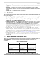
Target CPU Window
The Target CPU window is the main window of the Device Initialization design. The window contains
the control buttons at the top of the window and working area that allows you to browse and configure the
CPU peripherals. To open this window, use the pop-up menu for the CPU component in the project tree.
Figure 1. CPU Component Pop-up Menu
2.1.1
Design Control Buttons
The Target CPU window contains the following control buttons:
• Select CPU package — Lists available packages from the current Target CPU. From the list of
packages, you can choose the one to be used in the design. For details, refer Section 3.4, “Changing
CPU”.
• Generate Code — Invokes the Code Generation dialog box allowing you to generate the
initialization code according to the current settings. For details, refer Section 3.2, “Code
Generation and Usage”.
Processor Expert Software — Microcontrollers Driver Suite Device Initialization User Manual, Rev. 2.10
Freescale Semiconductor
5
User Interface
2.1.2
Work Area
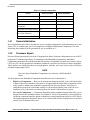
This area allows you to configure the CPU peripherals by adding the Peripheral Initialization Components.
For details, refer Section 3.1, “Peripheral Initialization Components”.
The Work Area window shows:
• Peripherals available on the MCU and their allocation by components.
• Pins and their allocation by components.
• Useful information that is available in the status line if the mouse cursor is placed on pin,
component or peripheral.
The following information about each pin is displayed on the package:
• Pin name (either default or user defined).
• Icon of a component that uses (allocates) the pin.
• Direction of the pin (input, output, or input/output) symbolized by blue arrows, if a component is
connected.
2.1.3
Hints
A hint appears when the mouse cursor is placed on a specific item. A pin hint contains:
• Pin number
• Pin name
• Owner of the pin (component that allocates it)
• Short pin description
NOTE
The pin hint is available only in the package view mode
A component icon hint contains:
• Component type
• Component description
2.1.4
General Pop-up Menu
The General Pop-up menu appears when you right-click anywhere in the Device Initialization window.
It contains the following commands:
• Zoom in — Shows the help page.
• Zoom out — Shows the help page.
• Rotate — Shows the help page.
Processor Expert Software — Microcontrollers Driver Suite Device Initialization User Manual, Rev. 2.10
6
Freescale Semiconductor
User Interface
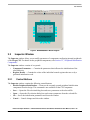
Figure 2. MC9S08QG8CFF Block Diagram
2.2
Inspector Window
The Inspector window allows you to modify parameters of components configuring internal peripherals
of the Target CPU. For details on the peripheral components, refer Section 3.1, “Peripheral Initialization
Components”.
The Inspector window consists of two panels:
• Component Parameters — Contains the parameters that influence the initialization of the
selected device.
• Register Details — Contains the values of the individual control registers that are set by a
generated initialization code.
2.2.1
Control Buttons
The Inspector window contains the following control buttons:
• Disable Peripheral Intialization — Removes the currently opened peripheral initialization
component from the design. This command is not available for the CPU component.
• Save — Opens the file selection dialog box and saves parameters to the selected file.
• Open — Opens the file selection dialog box and restores parameters from the selected file.
• Ok — Saves the initialization parameters and closes the window.
• Cancel — Cancels changes and closes the window.
Processor Expert Software — Microcontrollers Driver Suite Device Initialization User Manual, Rev. 2.10
Freescale Semiconductor
7
User Interface
2.2.2
Component Parameters Panel
The Component Parameters panel contains three columns:
• Item names — Items that are to be set are listed in the second column of the Inspector. Groups of
items describing certain features can be collapsed or expanded by double clicking on the first line
of the group.
• Selected settings — Settings of the items are made in this column. If you wish to select from
pre-defined values, there is a drop-down menu with the list of available options. There are radix
change buttons 'H','D','B' for switching value radix to Hexadecimal, Decimal and Binary, in case
such change is reasonable.
• Setting status — Current setting or an error status may be reflected on the same line, in the
rightmost column of the Inspector. The error is also displayed in the item's hint.
The settings with errors are marked with red color and the description for the error can be found in the
rightmost column.
A parameter can be presented as read-only and you cannot change its content. Such read-only values are
shown in grey.
2.2.3
Register Details
The Register Details panel shows values of individual control or data registers related to the currently
selected CPU peripheral and reflects the settings in the Component Parameters panel.
On some peripherals, there may be present an additionally modified registers section within this panel that
lists the registers that are initialized but belong to a different peripheral.
The following two types of rows can be found in this panel:
• Whole register content — The row contains the following columns:
— Name — Specifies name of the register according to the CPU datasheet.
— Init. Value — Specifies the initialization value of a register or bit computed according to the
settings in the Component Parameters panel. This is the last value written by the initialization
function to the register.
NOTE
For some registers, the value read from the register afterwards can be
different than the last written value. For example, some interrupt flags are
cleared by writing 1. For details on registers behavior, refer MCU manual.
If the row is active, the value can be changed using the keyboard. The field also contains a radix button
(H,D,B) that allows you to switch between Hexadecimal, Decimal and Binary formats of the value. The
value that contains undefined bits is always shown in binary format.
— Address — Specifies address of a register.
• Individual bit of the register — These rows can be unfolded under each register containing values
and the names of individual bits. Bits are sorted from the highest to lowest weight. The bit rows of
a register can be shown or hidden using the plus/minus icons.
Processor Expert Software — Microcontrollers Driver Suite Device Initialization User Manual, Rev. 2.10
8
Freescale Semiconductor
User Interface
2.3
Code Generation Options Dialog Box
The Code Generation Options dialog box is invoked at each code generation (using the Generate Code
button). You can specify the options influencing the format and placement of the generated code. The
options are divided into two groups using tabs.
2.3.1
Basic Options
Basic options include the following options and option groups:
• Generated file types available: For details on generated files, refer Section 3.2, “Code Generation
and Usage”.
— C — Generates the code in the C language. This option is not available for the assembly
projects.
• After Generation:
— Save and add files to the project — The files produced by Processor Expert are named using
the value of the Generated Module Name field. The files are automatically added to the
Generated Code folder of the Code Warrior project.
— Create file and do not add to project — The code will be generated into the newly created
untitled editor files.
• Generated module name — Specifies name of the files where the initialization code will be
generated.
2.3.2
Advanced Options
The following options modify the generation of code:
• Generate register modification only if initialization value does not match reset state — This
option neither affects the registers writable only once (for example CONFIGx) nor the registers
placed in FLASH (for example MORx).
• Generate comments about register modification — Source code will contain comments with
descriptions of the registers values.
• Generate interrupt vector table — Interrupt vector table content will be generated to the output
file.
• Generate interrupt service routine templates — Tool will generate empty interrupt routines
definitions for all enabled interrupts according to the components parameters. For details, refer
Section 3.3, “Defining Interrupt Service Routines”.
• Generate initialization of registers writable only once — These registers can be written only
once after reset due to technological or safety reasons. This option enables the generation of
initialization code for these registers.
• Generate initialization of register placed in FLASH — Initialization of these registers will be
done during the programming of the application code to the FLASH memory.
• After code generation show description how to use the generated files — If this option is
enabled, a dialog box with the short description of the generated modules and their usage is
displayed after every code generation.
Processor Expert Software — Microcontrollers Driver Suite Device Initialization User Manual, Rev. 2.10
Freescale Semiconductor
9
Using Device Initialization Tool
2.3.3
•
3
Common Options
Show this dialog every time before code generation — Use this check box to enable or disable
appearance of this dialog box before every code generation.
Using Device Initialization Tool
The following sub-topics describe basic principles and tasks related to device initialization:
• Peripheral Initialization Components
• Code Generation and Usage
• Defining Interrupt Service Routines
• Changing CPU
• Converting Project to Use Device Initialization
3.1
Peripheral Initialization Components
A Peripheral Initialization Component is an object that provides a human-readable interface to the
initialization parameters of a selected on-chip CPU peripheral. The parameters of the Peripheral
Initialization Component represent the settings of all peripheral registers in the clear tabular form. The
names of the Peripheral Initialization Components are Init_<peripheral> and they are specific for each
CPU family.
3.1.1
Adding Component
The components can be added to the design using the Target CPU window. Click on the unallocated
peripheral to add a new component. The new component is preset to work with the selected device.
Inspector window appears allowing you to configure parameters of the component.
3.1.2
Component Parameters and Device Registers
Every component contains a group of parameters (properties) that describe the desired initialization state
of the device. These parameters are automatically transformed to values of control registers related to the
selected peripheral. The Inspector window shows both - component parameters and resulting registers
values.
The component parameters are grouped in several categories by type. The following groups are commonly
present in peripheral initialization components:
• Settings — Common peripheral parameters.
• Pins — Configuration of the pins related to the peripheral.
• Interrupts — Configuration of the interrupts and interrupt service routines related to the peripheral.
For details, refer Section 3.3, “Defining Interrupt Service Routines”.
• Initialization — Parameters related to the peripheral initialization.
Processor Expert Software — Microcontrollers Driver Suite Device Initialization User Manual, Rev. 2.10
10
Freescale Semiconductor
Using Device Initialization Tool
3.1.3
CPU components
A CPU component is the component that configures the parameters of the CPU core, such as clock source
and frequency and power-saving capabilities. The CPU component is always present in design and cannot
be removed. The CPU component contains the following parameter groups:
• Clock Settings — Configuration of the CPU timing.
• Internal Peripherals — Configurations of the peripherals not supported by separate components
and settings that can be shared among components.
• CPU Interrupts — Configuration of the interrupts related to the CPU core.
3.2
Code Generation and Usage
The following sub-topics describe basic principles and tasks related to code generation:
• Starting Code Generation
• Generated Code
• User Changes in Generated Code
• Using Generated Code
3.2.1
Starting Code Generation
To generate code:
1. Click the Generate Code button in the Target CPU. The Code Generation Options dialog box
with the code generation options appears. For details, refer Section 2.3, “Code Generation Options
Dialog Box”.
2. Click on the Generate button in the Options dialog box. The source code initializing the MCU
registers according to the specified component parameters is generated. The generated modules
are added into the project and can be found in the Sources sub-folder of the project.
3.2.2
Generated Code
During the Code Generation process, the Device Initialization tool generates the initialization code for the
CPU peripherals allocated by the components. The generated code reflects the configuration of the
components' parameters and is contained in the function named MCU_init. You should call this function
at the beginning of the application code to initialize peripherals.
In the ColdFireV1 MCUs, an additional function is generated, named __initialize_hardware. It contains
settings of the clock source, the core registers and the system control registers (SOPTx, SPMSCx, all
write-once registers). This function is called from the after-reset startup code.
The generated module consists of two files:
• Implementation file containing the code of the initialization function(s) and optionally the interrupt
vectors table.
• Interface file containing the declarations that can be referenced by you. This file is generated only
if the files are stored to a disc.
Processor Expert Software — Microcontrollers Driver Suite Device Initialization User Manual, Rev. 2.10
Freescale Semiconductor
11
Using Device Initialization Tool
Depending on the After generation option, the files can be stored to a disk and added to the current project
or just shown in the editor as untitled files. For details, refer Section 2.3, “Code Generation Options Dialog
Box”.
Device Initialization tool can generate the following types of initialization code:
• C language — The implementation file has the extension .c and the interface file has the extension
.h.
A default name for the generated module is ' MCUInit '. An Initialization code format, the generated
module name, and other code generation options, can be configured in the Options dialog box. For details,
refer Section 2.3, “Code Generation Options Dialog Box”.
3.2.3
User Changes in Generated Code
If the content of generated modules is written to the disk, it always overwrites the existing files during
every code generation. As a result, all the modifications done by you are discarded with the following
exceptions:
• User definitions (or generally any other source code) in .C (or .asm) placed in the special comment
marks. In case of C language, it looks like:
/* User declarations and definitions */
User source code...
/* End of user declarations and definitions */
• Content of interrupt service routines that is assigned to any interrupt(s) in the peripheral
initialization components. For details, refer Section 3.3, “Defining Interrupt Service Routines”.
• Unused interrupt service routines (no component contains their name). They do not disappear but
are moved to the end of the file. The generated comments before and after the ISR must not be
modified for this feature to work properly.
NOTE
No changes done by you in the .h file (or .inc in case of assembly language)
are preserved. The file is always overwritten.
3.2.4
Using Generated Code
To call MCU_init function from the main file, it is necessary to do the following modifications in your
code:
• Device initialization, by default, generates an interrupt vectors table containing all interrupt vectors
(it can be disabled in the Options dialog box. For details, refer Section 2.3, “Code Generation
Options Dialog Box”). Existing interrupt vector definitions have to be removed or commented out
to avoid a conflict.For details on configuring interrupt vectors in Device Initialization, refer
Section 3.3, “Defining Interrupt Service Routines”.
• Add a call to the generated MCU_init function at the beginning of the application main routine.
The newly created projects already contain this line.
Processor Expert Software — Microcontrollers Driver Suite Device Initialization User Manual, Rev. 2.10
12
Freescale Semiconductor
Using Device Initialization Tool
NOTE
The prototype or external declaration of the MCU_init function or a
command including the interface file with this declaration should be present
in the module where the MCU_init is called. In a new project, it is already
there in the main file.
3.3
Defining Interrupt Service Routines
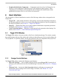
Some Peripheral Initialization components allow the initialization of an interrupt service routine.
Interrupt(s) can be enabled in initialization code using appropriate parameters that can be found within the
group Interrupts. After enabling, the specification of an Interrupt Service Routine (ISR) name using the
ISR name property is required. This name is generated to Interrupt Vector table during the code generation
process. For details, refer Section 3.2, “Code Generation and Usage”.
Note that if the ISR name is filled, it is generated into the Interrupt Vector Table even if the interrupt
property is disabled.
Figure 3. Interrupt Setup
Enabling or disabling peripheral interrupts during runtime has to be done by the user's code.
3.3.1
Interrupt Service Routines Code
The ISR with the specified name has to be declared according to the compiler conventions and fully
implemented by you. Declarations of the ISRs that do not exist yet can be generated automatically during
the code generation process into the generated module if the option Generate interrupt service routine
templates is enabled. For details, refer Section 2.3, “Code Generation Options Dialog Box”.
The contents of interrupt service routines, written by you, that are assigned to any interrupt within the
components parameters are protected against being overwritten during the code generation process. In case
the interrupt service routine is not assigned to any interrupt, it is moved to the end of the file.
WARNING
You are responsible for synchronizing ISR names in the code and ISR
names specified in components. If an ISR is renamed, the name has to be
changed in the component(s) where this ISR name is assigned and vice
versa. This has to be done before next code generation, otherwise the newly
specified ISR would not be found and the existing ISR with an old name will
be treated as unassigned, that is, it will be moved to the end of file.
Processor Expert Software — Microcontrollers Driver Suite Device Initialization User Manual, Rev. 2.10
Freescale Semiconductor
13
Using Device Initialization Tool
3.4
Changing CPU
The following sub-topics describe basic tasks related to CPU changes:
1. Changing CPU package
2. Components Assignment
3.4.1
Changing CPU package
The type of the CPU package can be changed using the Select CPU Package button in the Device
Initialization window. For details, refer Section 2.1, “Target CPU Window”.
3.4.2
Components Assignment
If some peripherals of the MCU set by components are not supported by the new MCU derivative, the
project is switched to, a dialog box with a list of the unsupported items is shown. You are asked to confirm
that these items will be removed from the design.
3.5
Converting Project to Use Device Initialization
This section guides you through a conversion from a plain C or assembly (if assembly is supported) project
to the project using the Device Initialization plugin and a peripheral initialization code generated by this
tool.
WARNING
Note that in most cases, this conversion involves necessary manual changes
in the application code, because the register interrupt vectors table
definitions created by you often conflict with Device Initialization
definitions. Don't forget to backup the whole project before the conversion.
Some files will have to be removed from the project. The conversion is
recommended for experienced users only.
The following steps should be done to convert the project:
1. Select the menu command File > New > Other.
2. Within the Select a wizard dialog box, select Processor Expert / Enable Processor Expert for
existing C project and click on the Next button.
3. Select the project that you would like to convert and the project type Device Initialization.
4. Select the MCU that the project is designed for.
5. Select the MCU variant(s) and Processor Expert configurations that you would wish to have
available in the project.
6. Review the actions that Processor Expert is about to perform. Ensure that you have backed-up
your project before confirming by clicking on Finish.
7. Add a call to the generated MCU_init function at the beginning of the application main routine.
For details, refer Section 3.2, “Code Generation and Usage”.
Processor Expert Software — Microcontrollers Driver Suite Device Initialization User Manual, Rev. 2.10
14
Freescale Semiconductor
Help Revisions History
8. For Kinetis family projects, it is necessary to remove the files kinetis_sysinit.c and
kinetis_sysinit.h from Project_Settings/Startup_Code. This module contains definitions that
conflict with Processor Expert definitions.
4
Help Revisions History
The current revision number is 2.10 (Generated: 27.5.2011 16:53:58)
Processor Expert Software — Microcontrollers Driver Suite Device Initialization User Manual, Rev. 2.10
Freescale Semiconductor
15
Help Revisions History
Processor Expert Software — Microcontrollers Driver Suite Device Initialization User Manual, Rev. 2.10
16
Freescale Semiconductor
How to Reach Us:
Home Page:
www.freescale.com
Web Support:
http://www.freescale.com/support
USA/Europe or Locations Not Listed:
Freescale Semiconductor, Inc.
Technical Information Center, EL516
2100 East Elliot Road
Tempe, Arizona 85284
1-800-521-6274 or
+1-480-768-2130
www.freescale.com/support
Europe, Middle East, and Africa:
Freescale Halbleiter Deutschland GmbH
Technical Information Center
Schatzbogen 7
81829 Muenchen, Germany
+44 1296 380 456 (English)
+46 8 52200080 (English)
+49 89 92103 559 (German)
+33 1 69 35 48 48 (French)
www.freescale.com/support
Information in this document is provided solely to enable system and software
implementers to use Freescale Semiconductor products. There are no express or
implied copyright licenses granted hereunder to design or fabricate any integrated
circuits or integrated circuits based on the information in this document.
Freescale Semiconductor reserves the right to make changes without further notice to
any products herein. Freescale Semiconductor makes no warranty, representation or
guarantee regarding the suitability of its products for any particular purpose, nor does
Freescale Semiconductor assume any liability arising out of the application or use of
any product or circuit, and specifically disclaims any and all liability, including without
limitation consequential or incidental damages. “Typical” parameters which may be
provided in Freescale Semiconductor data sheets and/or specifications can and do
vary in different applications and actual performance may vary over time. All operating
parameters, including “Typicals” must be validated for each customer application by
customer’s technical experts. Freescale Semiconductor does not convey any license
Japan:
Freescale Semiconductor Japan Ltd.
Headquarters
ARCO Tower 15F
1-8-1, Shimo-Meguro, Meguro-ku
Tokyo 153-0064
Japan
0120 191014 or
+81 3 5437 9125
[email protected]
under its patent rights nor the rights of others. Freescale Semiconductor products are
Asia/Pacific:
Freescale Semiconductor China Ltd.
Exchange Building 23F
No. 118 Jianguo Road
Chaoyang District
Beijing 100022
China
+86 10 5879 8000
[email protected]
claims, costs, damages, and expenses, and reasonable attorney fees arising out of,
For Literature Requests Only:
Freescale Semiconductor
Literature Distribution Center
1-800 441-2447 or
+1-303-675-2140
Fax: +1-303-675-2150
LDCForFreescaleSemiconductor
@hibbertgroup.com
Document Number: PEXDRVSDEVINUG
Rev. 2.10
08/2011
not designed, intended, or authorized for use as components in systems intended for
surgical implant into the body, or other applications intended to support or sustain life,
or for any other application in which the failure of the Freescale Semiconductor product
could create a situation where personal injury or death may occur. Should Buyer
purchase or use Freescale Semiconductor products for any such unintended or
unauthorized application, Buyer shall indemnify and hold Freescale Semiconductor
and its officers, employees, subsidiaries, affiliates, and distributors harmless against all
directly or indirectly, any claim of personal injury or death associated with such
unintended or unauthorized use, even if such claim alleges that Freescale
Semiconductor was negligent regarding the design or manufacture of the part.
Freescale, the Freescale logo, CodeWarrior, Processor Expert are
registered trademarks of Freescale Semiconductor, Inc., Reg. U.S. Pat. &
Tm. Off.
All other product or service names are the property of their respective
owners.
© 2011 Freescale Semiconductor, Inc.