1
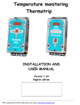
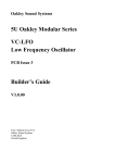
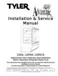
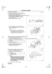
LI–24
LIGHTING - HEADLIGHT ASSEMBLY LH
HEADLIGHT ASSEMBLY LH
BODY AND ELECTRICAL
LIGHTING
COMPONENTS
LI
FRONT BUMPER ASSEMBLY
HEADLIGHT ASSEMBLY LH
E131554J01
LI–25
LIGHTING - HEADLIGHT ASSEMBLY LH
CLEARANCE LIGHT BULB SOCKET
HEADLIGHT BEARING MOTOR LH
CLEARANCE LIGHT BULB
HEADLIGHT LEVELING
MOTOR PACKING
FRONT TURN SIGNAL LIGHT BULB
HEADLIGHT BULB NO. 2
FRONT TURN SIGNAL
LIGHT BULB SOCKET
LI
HEADLIGHT
COVER NO. 1
HEADLIGHT BULB NO. 1
HEADLIGHT ASSEMBLY LH
4 LIGHT TYPE
CLEARANCE LIGHT BULB
HEADLIGHT LEVELING MOTOR LH
CLEARANCE LIGHT BULB SOCKET
HEADLIGHT LEVELING MOTOR PACKING
FRONT TURN SIGNAL
LIGHT BULB
FRONT TURN SIGNAL
LIGHT BULB SOCKET
HEADLIGHT ASSEMBLY LH
HEADLIGHT BULB NO. 1
HEADLIGHT COVER NO. 1
2 LIGHT TYPE
E132719J01
LI–26
LIGHTING - HEADLIGHT ASSEMBLY LH
Support Bracket
LI
Headlight Protector Retainer
UPR LH NO. 2
Headlight Protector Retainer UPR LH
Headlight Protector
Retainer
LWR LH
E132718J01
REMOVAL
Pin
E128798
1.
DISCONNECT BATTERY NEGATIVE TERMINAL
2.
REMOVE FRONT BUMPER ASSEMBLY (See Page ET-2)
3.
REMOVE HEADLIGHT ASSEMBLY LH
(a) Remove the 2 bolts, screw and clip.
(b) Remove the pins of the headlight bracket. Then remove the
headlight assembly LH.
LIGHTING - HEADLIGHT ASSEMBLY LH
LI–27
DISASSEMBLY
1.
REMOVE NO. 2 HEADLIGHT BULB
(a) Turn in the direction of the arrow shown in the illustration and
remove headlight bulb No. 2.
LI
E132270J01
2.
REMOVE HEADLIGHT BULB NO. 1 (4-LIGHT HEADLIGHT
SYSTEMS)
(a) Remove the socket cover.
2 Light Type
4 Light Type
E132183J01
(b)
(c)
Remove the set spring.
Remove headlight bulb No. 1.
NOTICE:
Do not touch the glass part of the bulb.
LI–28
LIGHTING - HEADLIGHT ASSEMBLY LH
3.
REMOVE FRONT TURN SIGNAL LIGHT BULB
(a) Rotate the front turn signal light socket in the direction shown in
the illustration, and remove the front turn signal light bulb
together with the front turn signal light socket.
4 Light Type
2 Light Type
LI
E132183J02
(b)
4.
Remove the front turn signal light bulb from the front turn signal
light socket.
REMOVE CLEARANCE LIGHT BULB
(a) Turn the clearance light socket in the direction shown in the
illustration, and remove the clearance light bulb together with
the and clearance socket.
2 Light Type
4 Light Type
E132183J03
(b)
Remove the clearance light bulb from the clearance light
socket.
REASSEMBLY
1.
INSTALL CLEARANCE LIGHT BULB
(a) Install the clearance light bulb in the clearance light socket.
(b) Install the clearance light bulb together with the clearance light
socket.
LIGHTING - HEADLIGHT ASSEMBLY LH
LI–29
2.
INSTALL FRONT TURN SIGNAL LIGHT BULB
(a) Install the front turn signal light bulb in the front turn signal light
socket.
(b) Install the front turn signal light bulb together with the front turn
signal light socket.
3.
INSTALL HEADLIGHT BULB NO. 1
(a) Install headlight bulb No. 1.
(b) Lock the set spring.
(c) Install the socket cover.
4.
INSTALL HEADLIGHT BULB NO. 2 (4-LIGHT HEADLIGHT
SYSTEMS)
(a) Install the headlight bulb No. 2.
(b) Lock the set spring.
(c) Install the socket cover.
INSTALLATION
1.
INSTALL HEADLIGHT ASSEMBLY LH
2.
INSTALL FRONT BUMPER ASSEMBLY
3.
CONNECT BATTERY NEGATIVE TERMINAL
4.
PREPARATION FOR HEADLIGHT ADJUSTMENT(See Page LI-29)
5.
ADJUSTMENT OF HEADLIGHT AIM (See Page LI-31)
6.
PREPARATION FOR ADJUSTMENT OF FOG LIGHT BEAM AIM
(See Page LI-34)
7.
ADJUSTMENT OF FOG LIGHT AIM (See Page LI-34)
8.
PERFORM INTIALIZATION
(See page SS-10 for details.)
ADJUSTMENT
1.
PREPARATION FOR HEADLIGHT ADJUSTMENT
(a) Adjust the tire air inflation pressure to the specified value.
(b) Seat a person in the driver's seat.
(c) Replenish oils to the specified levels. Fill up the tank with fuel.
(d) Mount the tools, jack and spare tire at the specified positions.
(e) Rock the vehicle in the up-and-down direction, as well as in the
right-and-left direction to settle the suspension.
(f)
Set the engine speed to 1500 r/min or more. (If the engine
speed is too low, the light terminal voltage drops, making it
difficult to recognize the cut-off line.)
HINT:
Cut-off line: Boundary line between the bright zone and the dark
zone in the low beam.
(g) If the vehicle is equipped with a headlight leveling switch, adjust
the leveling switch to zero.
LI
LI–30
LIGHTING - HEADLIGHT ASSEMBLY LH
2.
Upper/Lower Aiming
Left/Right Aiming
2 Lights
LI
Left/Right Aiming
(High Beam)
Left/Right Aiming
(Low Beam)
Upper/Lower
Aiming
(High Beam)
Upper/Lower Aiming
(Low Beam)
4 Lights
PHOTOMETRIC AXIS ADJUSTMENT
(a) Adjust the photometric axis of the low beam according to the
instruction manual of the headlamp screen to be used.
LI–31
LIGHTING - HEADLIGHT ASSEMBLY LH
3.
ADJUSTMENT OF HEADLIGHT AIM (WHEN USING LOW BEAM
SCREEN)
(a) Prepare a screen for the adjustment as indicated in the figure.
1.7
1.7
Center of the headlamp
LI
Cut off line
(Reference position)
1.0
1.2
1.5
Elbow point
:Reference range of Elbow points
Unit:%
E133905
(b)
(c)
HINT:
The illustration is for RH vehicles. For LH vehicles, the
illustration is symmetrically reverse in relation to the vertical
center line.
Place the screen at a distance of three meters ahead of the
light. Align point F with the center of the light.
HINT:
This normal placing can be carried out easily when a screen is
affixed to the lens of the headlamp tester (for high beam use).
Turn on the low beams of the headlights. Perform the
adjustment in such a way that the elbow point comes into the
shadow section on the screen.
NOTICE:
Perform the adjustment by turning the aiming screw in the
tightening direction. (When performing the adjustment in
the loosening direction, first loosen the screw then turn it
in the tightening direction.)
HINT:
Reference position of elbow point
LI–32
LIGHTING - HEADLIGHT ASSEMBLY LH
Vertical position
Within the range between 1.0% and 1.5% below the horizontal line
that passes through the center of the light (Reference position: 1.2%
below)
Horizontal position
Within 1.7% left or right of the vertical line that passes through the
center of the light (Reference position: on the vertical line that passes
through the center of the light)
CORRECTION
1.
LI
INSTALL HEADLIGHT PROTECTOR RETAINER UPPER LH
HINT:
If the headlight unit LH is the only installed part that is damaged, you
can use the repair bracket as shown in the illustration below as an
inexpensive workaround. However, this is limited to cases in which
the headlight assembly LH itself is not damaged.
Headlight Protector
Retainer UPR LH
Headlight Protector Retainer
UPR LH NO. 2
2 Light
Type
4 Light
Type
Alternate Bracket
(Install With Screw)
E132261
(a)
(b)
After disconnecting the damaged part, reshape it using
sandpaper.
NOTICE:
After shaving down the damaged spots in an approximate
way, fit the headlight protector retainer into the boss part.
Then shave down the parts that still do not fit in order to
shape the retainer so that it can be installed.
Install the headlight protector retainer upper LH with the 2
screws.
HINT:
Install the other retainers using the same method.
2.
INSTALL HEADLIGHT PROTECTOR RETAINER UPPER LH N0. 2
3.
INSTALL HEADLIGHT PROTECTOR RETAINER LOWER LH