1
2530 San Pablo
94702
_. Avenue Berkeley,CA.
.
415/549-3854 • TELEX 172029 SPX
CPU/68000
USER'S MANUAL
68000-BASED
CENTRAL PROCESSING UNIT BOARD
FOR THE I.E.E.E. 696/5-100 BUS
Dual Systems Control Corp.
2530 San Pablq AveDue
Berkeley, CA
COPYRIGHT @
94702
1982 BY DUAL SYSTEMS CONTROL CORP.
ALL RIGHTS RESERVED
Rev. B
Dual Systems CPU/68ooo User's Manual
Table of Contents
Introduction
2
Specifications
· . . . . . . .... . . . . .. .. . ... . . . . .. .. ...
Booting with the Monitor
On-Board ROM
Address Bus
Data Bus
3
4
·. ...... .. ......... .. . . ....... .... 8
·. ... .. .... .. . .... ......... ....... 12
.... ....... ....... ....... . . ... .. .... . 14
TMA Control
14
Interrupt Modes
15
Appendix A.
.. . . . . .... . . ..... ... . . ....... ... .
Selecting ROMs . . . .. .. . .. . .. . . . .. . . .
16
Appendix B.
Details of S-100 interface
Appendix C.
Appendix D.
.. ..... . .
Special Configurations . . . .. . . . . . . ..
A Few Programs . . . ... ... . ........ .. .
1
17
18
19
INTRODUCTION
The Dual Systems CPU/68oo0 is a high-performance CPU board
combining the Motorola MC68000 chip, the logic circuitry
necessary for interfacing to the S-100 bus in full compliance
with the IEEE-696 specification, and ROMs containing a powerful
monitor. Among its highlights are:
o
o
o
o
o
o
o
o
o
8 MHz 68000 microprocessor
4 MHz S-100 bus operation
24 bit extended address bus
16 bit data transfers
8 bit transfers for compatibility with older peripherals
On chip interrupt controller
Operation with up to 16 DMA devices
Up to 8 Kilobytes of on board ROM
Supports I/O mapped peripherals
The Dual Systems CPU/68000 board is based on the Motorola
68000 processor, a high-performance microprocessor wi th 32-bi t
internal architecture and a large, uniform memory space. The
68000 features 16 32-bit registers, eight for addresses and eight
for data. Data can be accessed in byte, word, and long word
(32 Bit) quantities.
The board is designed to take' full advantage of new IEEE-696
S-100 features. 16 bit memory accesses double the effective
transfer rate of the 4 MHz S-100 bus. The processor fully
complies with IEEE specifications for a permanent bus master and
supports temporary bus master operation. Twenty-four address
lines allow direct access to 16 Megabytes of memory.
2
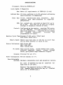
SPECIFICATIONS
Processor: Motorola MC68000-L8
Clock Speed: 8 Megahertz
Bus: Meets all requirements of IEEE-696 (S-100)
Address Bus: 24 bits; conforms to S-100 extended addressing
specifications (16 Megabytes)
Data
Bus: 16 bit bidirectional data transfers.
Also
supports byte data transfers to eight-bit
peripherals.
ROM: Two sockets are provided on board for up to
8K of ROM.
This ROM can be used for program
storage or excepti?n vectors or both.
Control: Configured as bus master, provides TMA protocol per IEEE-696. Provides automatic 8/16 bit
data path selection.
(requires 16 bit memory
for
program
execution).
Provides
64k
programmable I/O space.
Machine Cycle Time:Standard S-100 cycle: 750nS (min)
Fast Mode: 500nS (min)
Memory Speed: Memory must have data on the bus no later than
450 nS after address is valid on bus.
Status Indicators: RUN (Green LED)
HALT (Red LED)
HOLD (Yellow LED)
PC board: High quality epoxy, solder masked both sides,
screened component legend,
plated through
holes, gold plated edge connector fingers.
Sockets: Provided for all IC's
Power Consumption: 950 rnA nominal at 5 V.
User-Selectable
Options: Hardware relocatable boot and exception vectors.
AO line of address bus may be
high byte or low byte.
asserted
for
Phantom line asserted while in USER mode.
(for example disk controller may be disabled
while not in SYSTEM mode.)
3
Booting the CPU/68000 with Macsbug'
The CPU'/68000 comes wi th the Macsbug 1 moni tor installed in
the on-board ROM sockets. The monitor is factory configured for
use with a Godbout Interfacer· I serial I/O board.
If the
, Cpu/68000 is ordered with the Interfacer 2 and CMEM memory cards,
then the system can be brought up immediately.
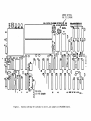
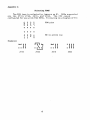
Set the dip-switches on the CPU/68000, Interfacer 2 , and CMEM
cards as shown in figures 1, 2, and 3.
After the dip-switches 'have been set properly, insert the
CPU/68000, the Interfacer, and the CMEM boards into the S-100
card cage.
Then connect the serial I/O cables between the
Interfacer card and the terminal. Be sure to connect pin 1 on the
ri bbon cable by the index on the edge connector.
Set the
terminal tor 9600 BAUD and upper case only. Now apply power. If
everything was done properly, you should see the Macsbug prompt
on the terminal:
MACSBUG 1.31
•
If this does not appear, turn off the power and recheck all
connections and dip-switch settings. Be sure the Interfacer and
the terminal are set for identical BAUD rates. Try again. If
there is still no response please call Dual Systems.
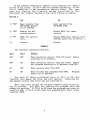
The dip-switch settings on the CPU/68000 map the monitor
program to location 020000H and provide for the boot vectors to
be read from the ROMs. These switches are described fully in
this manual.
The Interfacer2 switch setting define the first port to be
at I/O location OH and the second port (for printer or host
computer) at I/O location 2H.
In order to configure the board for use wi th your terminal
and printer, the port 1 baud rate must be set for the speed of
the console terminal and the Port 2 baud rate must match the
speed of the printer or the connection to the host computer. In
the figure these rates are 9600 and 300 respectively. Parity and
stop bi ts are set for use wi th an ADM 3A or ADM 5 terminal. For
more information regarding baud rates, stop bits, parity etc.,
refer to the Godbout Interfacer I manual.
The CMEM is set to span memory locations OH to 7FFFH. The
stacks reside in the top 1 Kbyte of this memory, the exeptlon
vectors in the low 1 Kbytes and the middle is available for user
programs. The remaining switches are set to enable extended
addressing, initially enable the board, and to allow writing to
the board. For more details refer to the CMEM manual.
1 Macsbug is a trademark of Motorola.
2 Interfacer is a trademark of Godbout Electronics
4
RI§
R2
RS
·VAI
CIO
o
5
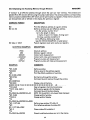
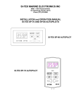
Figure 1.
II
00
ROM ADOR.
5ET FOR ~2~~~~H
41
49
tAlE IN TI£ U. S. A. REV. _
Factory settings for switches 51 and 52, and jumpers on CPU/68000 board.
PORT B CONFIG:
~-
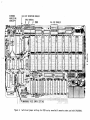
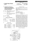
ALTERNATE CONFIGURATION - PORT B AS PRINTER PORT
FACTORY CONFIGURATION - PORT B USED FOR COMMUNICATION WITH HOSr
+INTCRFACCR+ AGmpuPro'MprOduct from ®ID~@(!)m~
PORT A CONFIG:
DUAL CHANNEL RS232 SERIAL liD
tx3~
J3
A
J1
J4
J5
B
J6
OJ
J2
--
rr
I
~
I
IC2-1489
()
C1
~- 0
01
0
o
C2
+)
ED-
U
U
(3 <3
~ 0
0
PORT A: 9600 BAUD
.
Ci PORT B:
UI
c=:::J '
~
IC6-1489
~ .
-ffD3
M
ex>
lX)OO
+]
IC30-7805
I
~~~~
-
1~,.' ~
,
0".
OOT
~~ :
III •
c=::::>, . . . . . . . .) PO RT A
g
-,
IC32-7812
~ ~~~~~~~~ J ADDR=OO ,01
R1:~DE
10
Figure 2.
IN USA
I'- - - :
~.
02 51
{
300 BAUD
~
..-
~N""
=lO;i,
0
~
....
U "'-_---J
IC11-1602
".
m
-,
~
---:
~
U>
~~
0
• -
!O 10 to Oi
c:::::>
ex> - - - :
0 •
.0
,_
..-----
-,
•
c::=) to c::::::>R 17c::::::::>
c::::::::>
..-
~
~
C==>
em
30
~I
COPYRIGHT 1979 GODBOUT ELECTRONICS
!,C20-25LS2521
20
G
40
Factory configuration of serial I/O board for operation with CPU/68000.
~
J,~
IC18-1602
i
c:::>
c:::=J
ABC§
'ABCJ1~
~
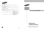
EXTENDED
ADDRESSING
ENABLED
Figure 3.
[/16 BIT OPERATION ENABLED
ALL 32K ENABLED
Switch and jumper settings for CMEM series nonvolatile memories when used with CPU/68000.
ON-BOARD ROM
Two ROM sockets are available on the CPU board to store up
to 8K bytes of data. The ROMs can be used to store programs,
interrupt vectors, or both. A variety of fi ve vol t only, 8 bi t
EPROMs or ROMs may be used. The CPU/68000 is factory configured
for use with 2732 EPROMs, see Appendix A for jumper installation
for alternate EPROMs.
Switches 81 and 82 determine the ROMs base address and their
mode of operation. Ei ther one of two condi tions may enable the
ROMs:
Using the ROMs to 8tore Programs:
The ROMs may be selected on any read from the address space
starting at the address specified by 81. This mode is selected
if 82-3 is on. 8ince only the most significant 8 address bits
are decoded the ROMS occupy a full 64 kilobytes
of memory.
Hardware relocation of the Exception Vectors:
The ROMs can be enabled on memory reads to the exception
vector address space. The MC68000 expects to find the exception
vectors stored in the first 1024 bytes of memory. Typically it
is desirable to store most vectors in RAM to allow software
control of traps,
interrupts etc.
However, the power on
sequence requires two 32 bit vectors for the initial stack
pointer and program counter.
The 68000 expects these 8 bytes at
memory locations zero (0) through 7 and they should be stored in
ROM to ensure their validity on power up.
Switch 82-1 ("EV", Enable for Vectors) determines whether
the vectors are read from on-board ROM or off-board memory
(usually ROM). If switch 82-1 is ON the on-board ROMs will be
accessed on a read from the exception vector space. If switch
82-1 is OFF, the vectors will be read from off-board memory.
Switch 82-2
("XV", eXception Vectors) determines which
exception vectors enable the ROMs. 82-2 in an ON position
enables the ROMs only for the two reset vectors. 82-2 in an OFF
position enables the ROMs for the first 64 exception vectors.
Normally 82-2 is kept in an on position. However, for some
dedicated applications it may be desirable to store the many
system exception vectors (divide by zero, trap, interrupt etc.)
in ROM.
If one desires to store exception vectors in an off-board ROM
(i.e. 82-1 off) 81 determines the new starting address of the
vectors.
8
If the address translation feature is not desired, 81 should
be set to all zeros. In this case the address appearing on the
bus is identical to the processor's address lines. The user
must not disable this feature unless non-volatile (and
previously set) memory resides in the first 8 bytes of memory.
Switch 2
ON
OFF
1) "EV"
Read vectors from
OFF-BOARD memory
at 31 address
Read vectors from
ON-BOARD ROMS
2 ) "XV"
Enable for ALL
system vectors.
Enable ONLY for reset
vectors.
ROMs for vectors
only.
Enable ROMs when reading from
address space set by switch 1.
Unused.
Unused.
3)
"R"
4)
Summary
The possible configurations are:
S2-1
32-3
Effect
OFF
OFF
Read exception vectors from off-board
starting at S1 address.
OFF
ON
Read exception vectors from off board memory
and program starting at 31 address from ROM.
ON
OFF
Read vectors only from ROM.
ON
ON
Read vectors and programs from ROM.
starts at 31 address.
memory
Program
For each of these configurations, if 32-2 is ON then
"vectors" only means the first two· boot vectors,
otherwiS'e all
the system vectors (the first 64) are referred to.
Note that even though the program address space starts at
the 31 address,
you must not overlap the program with the
exception vectors. If S2-2 is ON then the program can start at
location 08H, if 32-2 is OFF then the program must start after
location OFFH.
9
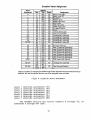
Exception Vector Assignment
Vector
Number(s)
0
2
3
4
5
6
7
8
9
10
11
12*
13*
14*
15*
16·23*
24
25
26
27
28
29
30
31
32·47
48·63*
64·255
Dec
.0
4
8
12
16
20
24
28
32
36
40
44
48
52
5f)
60
64
95
96
100
104
108
112
116
120
124
128
191
192
255
256
1023
Address
Hex
Space
Assignment
000
SP
Reset: I nitial SSP
004
SP
Reset: Initial PC
008
SD
Bus Error
DOC
Address Error
SO
010
SO
Illegal Instruction
014
Zero Divide
SO
CHK Instruction
018
SO
OlC
SD
TRAPV Instruction
Privilege Violation
020
SO
024
SO
Trace
028
SO
Line 1010 Emulator
02C
SO
Line 1111 Emulator
(Unassigned reserved)
030
SO
034
SO
(Unassigned, reserved)
SO
038
:Unassigned, reserved)
03C
SO
Unassigned reserved)
040
SO
Unassigned reserved)
05F
060
SO
Spurious Interrupt
Level 1 Interru pt Autovector
064
SO
Level 2 Interrupt Autovector
068
SO
Level 3 Interrupt Autovector
06C
SO
Level .:t Interrupt Autovector
SO
070
074
SO
Level 5 Interrupt Autovector
Level 6 Interrupt Autovector
078
SO
Leve I 7 Interru pt Autovector
07C
SO
080
SO
TRAP Instruction Vectors
OSF
(Unassigned, reserved)
OCO
SO
OFF
SO
User Interrupt Vectors
100
3FF
-
-
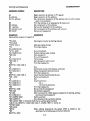
*Vector numbers 12 through 23 and 48 through 63 are reserved for future enhancements by
Motorola. No user peripheral devices should be assigned these numbers.
Figure 4. Exception Vector Ass1gnment
Level
Level
Level
Level
Level
Level
Level
1 interrupt autovector: VI5
2 interrupt autovector: VI4
3 interrupt autovector: VI3
4 interrupt autovector: VI2
5 interrupt autovector: VI1
6 interrupt autovector: VIO
7 interrupt autovector: NMI
The SYSTEM vectors are vector numbers 0 through 63, at
addresses 0 through OFF (255).
10
What happens on Power Up
After power up the 68000 loads the system stack pointer
and program counter from the first two exception vectors. These
two 32 bit vectors are stored in the least significant eight
bytes of memory. Since these vectors are required when power is
first applied, they should be stored in ROM. In this example,
the program counter vector points to location 020008H which is
the first instruction in the program in ROM, (after the boot
vectors).
If you wish to modify the moni tor, you could copy the
contents of the ROMS into another memory board, preferably
non-volatile RAM. (To read the ROMS, simply read from locations
20000 through 21 FFF.) Then you can modi fy the copy in RAM. To
execute the new version you must relocate the RAM to location
20000 and set S2-1 and S2-3 to OFF, so the monitor and the boot
vectors are read from the RAM. A sample program for a block move
is listed in Appendix D.
Format of Data Stored in ROMs
Since the ROMs support word transfers, sequential addresses
are stored in alternate ROMs. That is, one ROM (U2) holds the low
byte of each word and the other (U 1) holds the hi gh byte of each
word.
NOTE:
If S2-3 is ON (so that the S1 address is mapped to the ROMS)
you must make sure that no other memory lies in the address space
of the 64K block of memory starting at the S1 address.
11
ADDRESS BUS
The processor board supports an extended 24 bit address bus.
This allows the CPU to directly address up to 16 megabytes of
memory.
Such a vast address space eliminates the need for
cumbersome bank select schemes. Older boards responding to only
the 16 bit address bus may be used with this CPU but this would
restrict the total system address space to 64 kilobytes.
1/0 Space vs. Memory Space
The 68000 instruction set does not have an explicit
Input/Output instruction.
Motorola archi tects intended for all
68000 I/O to be memory mapped. Memory mapped I/O takes advantage
of the many powerful addressing modes for fast, efficient I/O
routines.
To support S-100 I/O mapped peripherals the processor board
dedicates the most significant 64 kilobytes of memory to I/O. As
a result, any memory access to hex address FFOOOO through FFFFFF
results in an I/O bus cycle. That is, such an access asserts
status outputs sINP or sOUT. This configuration allows efficient
memory mapped software while maintaining full compatibility with
existing I/O devices.
For example, hex address FF0002 corresponds to I/O port with
address 02. So the 68000 instruction:
MOVE.B
OFF0002H,DO
is similar to the 8080 instruction:
IN
02H
Note that 64 kilobytes of address space are dedicated to I/O
devices. This allows over 64 thousand input and output ports.
To support this many ports requires that I/O devices decode the
least significant 16 address bits. The IEEE specification allows
extended I/O addressing but does not require it.
The majority of current I/O boards decode only the least
significant 8 address bits. This gives 256 input and output
ports. The processor board can be used with such an I/O device.
Since the I/O board does not decode the full 16 bit I/O address
its ports address is replicated throughout the 64 kilobyte I/O
address space. The processor board functions quite well with
existing I/O boards and is capable of fully supporting future
extended I/O address boards as well.
If you are using an I/O board which only decodes the low
eight bits of the address then you can use the 16-bit word
addressing mode of the 68000. Since to the I/O board address
OFF0002 is indistinguishable from OFFFF02, and the 68000 sign
extends the word long address, you can also use the address
12
OFF02. So the above example could also be coded:
MOVE.B
OFF02.W,DO
AO
The 68000 address bus directly drives A1 through A23. The
CPU / 68000 comes factory j umpered for the updated IEEE-696
standard. That is, the most significant byte of each word is
stored at an even address and the least significant byte is
stored at the next odd address. Note that instructions, operands,
stack data, address vectors etc. are all stored at even
addresses.
The definition of AO may be reversed by carefully cutting
the trace marked LO (Low Odd) and installing a jumper to the
pad marked LE (Low Even).
13
DATA BUS
The 68000 transfers data over a single 16 bit bidirectional
bus. Programs must reside in ,16 bit memory, however, data bytes
may be accessed from byte wide memory.
Long words must be
transferred in sequential 16 bit bus cycles.
Byte data is
transferred over the corresponding data lines; high order (even
address) bytes on D15-DB, low order (odd address) bytes on D7-DO.
The S-100 bus has two 8 bit data paths, Data Odd and Data
Even). For byte transfers data is sent over the Data Even bus
for write operations and over the Data Odd bus for read
operations.
For word transfers Data Even and Data Odd are
ganged, forming a 16 bit bidirectional bus. During word bus
cycles the even (AO=O) byte is transferred over the Data Even bus
and the odd (AO= 1) byte over the Data Odd bus. On the 68000 the
even byte is most significant (D15-D8). If you have changed the
AO jumper on the CPU board then these definitions are reversed.
TEMPORARY BUS MASTER INTERFACE (TMA CONTROL)
The 68000 processor board functions as a permanent bus
master as specified in the IEEE proposed S100 standard.
Temporary bus masters (DMA devices) request the bus by asserting
control input HOLD. They receive control of the bus when the bus
master (68000 CPU) asserts control output hold acknowledge
(pHLDA) •
Upon receipt of HOLD the 68000 completes the current bus
cycle and then asserts pHLDA. The 68000 suspends all processing
until HOLD is released. A temporary master may now disable the
permanent bus masters address, data, status and control buses by
asserting the four disable lines ADSB, DODSB, SDSB and CDSB. The
temporary master now has complete control of the bus for as long
as it wishes.
When the bus is no longer needed control is
returned to the permanent ma~ter by releasing the bus disable
signals and finally, releasing HOLD.
The method of transferring the bus from the permanent bus
master to a temporary master is explicitly specified in the IEEE
bus standard section 2.8. Of significance is the method used to
transfer ownership of the control output bus. To ensure gl itch
free transfer, both the permanent and temporary master drive the
control output bus during the transfer period. Except for pHLDA,
all lines are driven at their non-asserted levels.
After a
specified time (125 nanoseconds) the temporary master asserts
CDSB, disabling the permanent master,s control output bus drivers
and acquiring control of the bus.
Up to 16 temporary masters may coexist in a system. A
distributed arbitration scheme determines the highest priority
device which then takes control of the bus upon assertion of
pHLDA.
14
In general, ,the 68000 will relinquish control of the bus
after the current bus cycle. However, if HOLD is received just
before the start of a bus cycle, the 68000 will go ahead with the
bus cycle, relinquishing control after its completion.
The 68000 instruction TAS (Test And Set) results in
different CPU timing than other instructions. Motorola defines
it as a read-modify write cycle. The instruction results in
sequential read and write cycles on the S-100 bus.
The two
cycles are indivisible, that is, the write cycle must follow the
read cycle.
This type of instruction allows meaningful
communications wi thin a mu1 tiprocessor or mul tiprocessing
environment. TAS is designed to prevent transfer of bus control
until the entire instruction has completed execution. Note that
two distinct S-100 cycles are completed, but no interrupts or bus
requests will be accepted until the second cycle has completed.
INTERRUPTS
The 68000 has a powerful internal interrupt controller.
There are seven levels of interrupt priority. All except the
non-maskable interrupt are software maskable via the system
status word.
The processor board is configured to accept seven of the
S-100 interrupt signals, VI5 through VIa and NMI, where VI5 has
the lowest priority. Note that NMI will always generate an
interrupt when asserted. VI6 and VI7 are not supported. The SlOa interrupt signals correspond to the MC68000 IPL interrupt
levels as follows:
S-100 definition:
68000 CPU notation:
VI5
IPl
VI4
IP2
VI3
IP3
VI2
IP4
Vll
IP5
VIO
IP6
NMI
IP7
After receiving an interrupt with priority greater than that
specified by the system status word, the 68000 loads the program
counter from the appropriate exception vector (a 32-bit address)
'and begins execution of the interrupt routine.
The seven
autovectors are vector numbers 25 through 31 (decimal) and reside
at locations 100 through 124 (hex). No interrupt acknowledge
cycle is needed.
15
Appendix A
Selecting ROMS
The ROM type is selected by jumpers on H1. ROMs supported
are the 2716, 2732, 2516, and 2532.
The CPU comes
configured for use wi th 2732 ROMs. Following is a diagram of H1:
G
N
D
P
e
P
2
0
P
2
ROM pins
1
• • • •
• • • •
A
1
3
Examples:
:-: II
2716
A
1
2
E
N
EN is active low
+
~
,
•
~
2732
16
:-: I I
2516
: I I1
2532
Appendix B
Details of the S-100 bus Interface for the 68000
FUNCTION OF M1
Status signal sM1 is asserted during any program (as opposed
to data) fetch. Historically, sM1 indicated that the current bus
cycle would require four clock periods instead of three clock
periods.
The extra clock period, required for instruction
decode, allowed time to refresh dynamic memory. With the 68000,
no assumption can be made about the length of a bus cycle based
on the level of sM1.
SIXTN Line
The CPU/68000 does not support seqential byte operations to
implement a sixteen-bit data transfer. Therefore it has no need
for the SIXTN line on the S-100 bus and it is ignored.
17
Appendix C
Special Configurations
Faster Memory Access When Used with Dual Systems Memories
When the CPU/68000 is used with the Dual Systems line of
FAST CMEM (Rev. B and later) memories, memory cycle time is
decreased by 25%. This allows the CPU/68000 to run at absolutely
full speed with no CPU wait states. This increased speed is
possible through the use of an asynchronous bus transfer
protocol. When the CPU commences a memory cycle, the CMEM
memories respond to a valid address on the·bus by asserting a
manufacturer-definable line (166) called FASTACK* and either
gates data onto or latches the data from the data bus.
Immediately after the CPU detects that FASTACK* has been
asserted, the processor completes the cycle.
If the memories being accessed do not respond with FASTACK*
a standard S-100 bus cycle is completed. Thus, both Dual FAST
CMEM and regular 16 bi t S-100 memories may be used in the same
system.
The CPU/68000 must have the pins 1abled "FAST" and "66"
jumpered together to enable fast mode.
Using the Phantom Line for System Protection
The 68000 is always in one of two modes: system mode or user
mode. When in user mode, it is usually desirable to not allow
the user access to anything which might impair the integrity of
the operating system or file system.
The CPU/68000 is capable of supporting a simple protection
scheme. Install a jumper between the pads marked "USER" and "PIt
(Phantom). When this jumper is installed, the Phantom line will
be asserted whenever the CPU is in user mode.
Then any I/O
(especially disks) which should only be acessed when in system
mode can be set to disable themselves when the Phantom line is
asserted. In addi tion, memory that should only be seen read or
changed by the operating system- directly, can also be set to be
disabled when the phantom line is asserted.
18
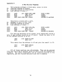
Appendix D
A Few Utility Programs
AO
A1
A2
0000
0002
0004
0006
AO
A1
A2
0000
0002
0004
0006
This program performs a block move, enter it with:
Starting address of source
Starting address of destination
Last address to move +, 1
32DB
LP1: MOVW AO@+,A2@+
B1CA
CMPL A2,AO
6DFA
BLTS·LP1
4EF9 0002 OODB JMP /200DB
MOVE A WORD
DONE?
REPEAT
.RETURN TO MACSBUG
This fills a block with a word.
ADDRESS of word to fill with
Starting address of block
Last address of block + 1
32DO
LP2: MOVW AO@,A1@+
B3CA
CMPL A2,A1
6DFA
BLTS LP2
4EF9 OOa2 OODB JMP /200DB
MOVE A WORD
DONE?
REPEAT
RETURN TO MACSBUG
For testing hardware with a scope, this repeatedly sends a
byte to any address (could be an I/O port). Sends the byte in DO
to the address pointed to by AO.
10BO
60FC
LP3: MOVB DO,AO@
BRAS LP3
This reads from the address in AO and puts the result in DO.
1010
60FC
LP4: MOVB AO@,DO
BRAS LP4
All of these routines are relocatable. They can be entered
into any free area of memory (such as 2000) with the MACSBUG OP
command. The entry parameters can be directly placed in the
registers, and the routine executed with the G command.
19
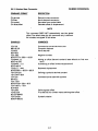
MACSBUG OPERATING INSTRUCTIONS
1.
INTRODUCTION
This document describes the operation of the MACSbug monitor after it has
been installed. It includes a complete description of all the commands
and examples of its use.
2.
OPERATIONAL PROCEDURE
After the CPU/68000 board has been installed, as per the manual, the user
should perform the following:
a.
Turn power ON to the system.
b.
Depress the RESET (black) button. -
The system should initialize and print:
MACSBUG 1.31
*
If these two lines do not print out, go back and check the CPU/68000 manual.
Check especially that the terminal and I/O board have the same BAUD rates.
3.
CO~~D
LINE FORMAT
Commands are entered the same as in most other buffer organized computer
systems. A standard input routine controls the system while the user types
a line of input. The delete (RUBOUT) key or control 'H' will delete the
last character entered. A control 'X' will cancel the entire line.
Control '0' will redisplay the line. Processing begins only after the
carriage return has been entered.
During output to the console the control 'W' will suspend the output until
another character is entered. The BREAK key will abort most commands.
The format of the command line is:
*COmmand parameters; options
where:
*
is the prompt from the monitor. The user does not
enter this. In the examples given, the lines beginning
with this character are lines where the user entered
a command.
1.
Note:
co
is the necessary input for the command. Each
command has one or two upper case letters necessary
in its syntax. In the examples, the entire command
may be used, but only those letters in upper case
in the syntax definition are necessary.
mmand
is the unnecessary part of the command. It is given
in the syntax definition only to improve readability.
If this part of the command was actually entered on
the command line, it would be ignored.
parameters
depends upon the particular command. Data is usually
in hex but most printable ASCII characters may be
entered if enclosed in single quotes. The system
also supports a limited symbolic feature allowing
symbols to be used interchangeably with data values.
joptions
modifies the nature of the command. A typical option
might be to disregard the checksum while reading a file.
MACSbug requires all commands to be entered in upper case letters.
If lower case letters are used, MACSbug will respond with
WHAT?
*
4.
EXAMPLE OF COMMAND PROCEDURES
MACSBUG 1.0
*P2
Power up or reset condition
MACSbug prompts with '*' user enters P2 to enter
transparent mode. (see page 3-19)
*TRAN SPARE NT *
Message printed to indicate user is now directly
connected with host system
User may now communicate directly with the host system. Typing a
control A at any time will exit to MACSbug.
(Control A)
*MACSBUG*
Message put out by MACSbug to indicate user is
now in MACSbug command mode
Download from EXORciser host
*READ ;=COPY FILE.MX,#CN
Display memory
*DM 1000
001000 70 01 70 02 70 03 70 04 70 OS 4E F8 10 00 FF FF p.p.p.p.p.N •••••
Set program counter to START
*PC 1000
Clear the trace display
*TD CLEAR
Specify which registers to print in display
*TD PC.22 00.1
Print the trace display
*TD
PC=lOOO 00=00
Set a breakpoint
*BR 1004
Trace command
*T TILL 0
PC=1002 00=01
Stopped at breakpoint
PC=1004 00=02
:*GO
Stopped at breakpoint
PC=1004 00=02
Program
is ready to run
*
2.
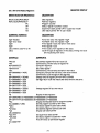
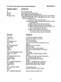
3.6 MACSbug COMMAND SUMMARY
COMMAND
reg#
reg # hexdata
reg # 'ASCII'
reg#:
class
class:
OM start end
SM address data
OPen address
SYmbol NAME value
W#
W#. len EA
M# data
Go
Go address
Go TILL add
BReakpoint
BR add: count
BR -address
BR CLEAR
TO
TD reg#. format
TD Clear
TDAU
TD A. 1 D. 1 L c
PAGE
T count
T TILL Address
:*(CR)
OFfset address
CV decimal
CV $hex
CV value, value
REad; =text
VErify; =text
PUnch start end
FOrmat hex
NUll hex
CR hex
TErminal baud
CAli address
P2
*..data..
Print a register
Put a hex value in the register
Put hex·equivalent characters in register
Print the old value and request new value
Print all registers of a class (A or D)
Sequence through-print old value request new
Display memory, hex-ASCII memory dump
Set memory with data
Open memory for read/change
Define and print symbols
Print the effective address of the window
Define window length and addressing mode
Memory in window, same syntax as register
Start running from address in program counter
Start running from this address
Set temporary breakpoint and start running
Print all breakpoint addresses
Set a new breakpoint and optional count
Clear a breakpoint
Clear all breakpoints
Print the trace display
Put a register in the display
Take all registers out of the display
Set all registers to appear in the display
Set register blocks or line separator
Trace one instruction
Trace the specified number of instructions
Trace until this address
Carriage return-trace one instruction
Define the global offset
Convert decimal number to hex
Convert hex to decimal
Calculate offset or displacement
Expect to receive'S' records
Check memory against'S' records
Print'S' records (tape image)
Program/initialize an ACIA
Set character null pads
Set carriage return null pads
Set terminal null pads to default values
JSR to user utility routine
Enter transparent mode
Transmit command to host
Break
CTL·A
CTL·D
CTL·H
CTL·W
CTL·X
Rubout
Del
The BREAK key will abort most commands
The control A key ends transparent mode
The control 0 key redisplays the line
The control H key deletes the last character entered
The control W key suspends output until another character is entered
The control X key cancels the entire line
The RUBOUT key deletes the last character entered
The DEL key deletes the last character entered
T
I
DESCRIPTION
3·5
3-6
3-7
3·8
3-9
3-10
3-11
3-12
3-13
3·14
3-15
3-16
3·17
3·18
3·19
)
3·4
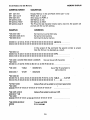
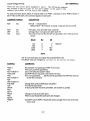
REGISTER DISPLAY
3.6.1 Set and Display Registers
68000 REGISTER MNEMONICS
DESCRIPTION
00,01,02,03,04,05,06,07
AO,A1,A2,A3,A4,A5,A6,A7
PC
SR
SS
US
Data registers
Address registers
Program counter
Status register (condition codes)
Supervisor stack pointer (A7 in supervisor mode)
User stack pointer (A7 in user mode)
COMMAND FORMATS
DESCRIPTION
reg# hexdata
reg# 'ascii data'
reg#:
reg#
class (where class=O or A)
class:
Put a hex value into register 'reg#'
Put ASCII value into register 'reg#'
Print register value and take in new value
Print register value
Print values of all registers in the class
Cycle through all registers in the class printing old value
and requesting new value
EXAMPLES
COMMENTS
-A5123
-A5
A5=00000123
Set address register A5 to hex value 123
Command to print the value of register A5
Computer response
Set a data register
Command to print old value and take in new value
Computer prompts with old value; new value entered
Command to cycle through all data registers
Change value of register DO from 45FE to 9EAB3
Carriage return (null line) means the value remains the same.
-04 FFFFFF
-DO:
DO=~=?45FE
-0:
DO=000045FE=?9EAB3
Dl=~=?(CR)
D2=~=?(CR)
D3=~=?(CR)
D4=OOF F FFFF =? (CR)
D5=~=? 55555
Change register 05 to a new value
D6=~=?(CR)
D7=~=?(CR)
-0
Display all data registers
DO=OOO9EAB3 ol=~ 02=~ 03=00000000
D4=OOFFFFFF 05=00055555 06=00000000 07=00000000
-PC:
Display and request input for program counter
PC=OOO8B3=? 2561
Set the program counter to new value
Set status register to zero (user mode)
-SR 0
-A74321
Set address register (same as US now)
-US
Display user stack pointer
US=00004321
Set supervisor stack pointer
-SS 7FFF
Set status register to supervisor mode
-SR 2000
Print A7 which is now the SS register
-A7
A7 =OOOO7FFF
-
3·5
MEMORY DISPLAY
3.6.2 Display and Set Memory
COMMAND FORMAT
DESCRIPTION
OM start end
OM start count
OM2 start end
SM address data
SM address 'ASCII"
SM address data N
Display Memory in hex and ASCII where start < end
Where start> count
Send output to PORT 2
Set Memory to hex
Set Memory to ASCII
The 'N' as the last character means start a new line; the system will
prompt with the current address
EXAMPLES
COMMENTS
-SM 2000 'ABC'
·SM 2003444546 'G'
-OM 2000 2010
Set memory to some ASCII data
Set some more locations
Command to dump memory
002000 41 424344 4546 4700 00 00 00 00-00 00 00 00 ABCDEFG ........ .
002010 00 00 00 00 00 00 00 00 00 00 00 00 00 00 00 00
In this version of the command the second number is smaller
than the first so it is decoded as a count
-OM 200312
002003 44 45 46 47 00 00 00 00 00 00 00 00 00 00 00 00 DEFG ........... .
002013 00 00 00 00 00 00 00 00 00 00 00 00 00 00 00 00................ .
-SM 1000 1 23456 7890 ABCDE 12345678
Size can be up to 8 characters
-OM 1000
001000 01 23 04 56 78 90 OA Be DE 12 34 56 78 00 00 00 ............... .
-SM 1000
'TABLE
• 00005678N
oooolOOC ?
'START
, 00023456
Use of the 'N' parameter to
start a new line
-OM 100020
001000 54 41 42 4C 45 20 20 200000 56 78 53 54 41 52 TABLE ..... VxSTAR
001010 54 20 20 20 00 02 34 5600 00 00 00 00 00 00 00 T ..... 4V ....... .
-OFFSET 2030
Global offset will be added to command parameters
A
-OM 1000
003030 FF FF FF FF FF FF FF FF FF FF FF FF FF FF FF FF
................
·SM 1005 1234 N
Global offset added to address 1005
00003037 ? AB
-OM 1000
003030 FF FF FF FF FF 12 34 AB FF FF FF FF FF FF FF FF
................
-SM 20000 AB CD EF
ERROR
•
Trying to set ROM
Error message
3·6
3.6.3 Open Memory for Read/Change
OPEN MEMORY
COMMAND FORMAT
DESCRIPTION
OPen address
Open memory at specified address and enter subcommand mode
SUBCOMMAND FORMAT
ADDRESS
CONTENT
·OP 1000
001000
001001
001002
001001
001000
001000
001000
*
*OP 1234
021234
**NOCHANGE**
021234
=
=
=
=
=
=
=
FF?
AB?
44 ?
AB?
12 ?
77 ?
77?
=
FF?
==
FF?
USER
ENTERS
12
(CR)
341
l
77=
=
99=
COMMENTS
Open memory location 1000
User enters data and system goes to next location
Carriage return means go to the next location
Up arrow means go to previous location
Can be entered without data
Equal sign means stay at same address
Can be used without any data
Period means return to MACSbug
Returns to command level
Example of trying to change ROM
Warning message
Does not abort command
3-7
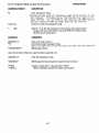
SYMBOLS
3.6.4 Define and Print Symbols
COMMAND FORMAT
DESCRIPTION
SYmbol name hex value
Put a symbol in the symbol table with a hex value or assign a new
value to a previously defined one. NAME can be 8 characters
long, consisting of: A·Z, 0·9, (period), and $ (dollar sign). It must
begin with letter (A·Z) or period.
Remove a symbol from the symbol table
Print the current value of the symbol (absolute)
Print the first symbol with the given value
Print the sorted symbol table
SY
SY
SY
SY
-name
name
value
NOTE
Offset is not used by this command. Some commands rec·
ognize the words TILL, ALL, and CLEAR as key words and
not interpret them as symbols.
will
EXAMPLES
COMMENTS
·SY XYZ 5000
·SY XYZ
XYZ =5000
·SY XYZ 123
·SY ABC34 2500
·SY Z17.RTS XYZ
·SY 123
XYZ =123
·SY B$67ABC 4300
·SY RFLAG 2300
·SY MVP2 9990
·SY
ABC34 00002500
RFLAG
00002300
Puts the symbol in the table
Command prints out the symbol's current value
Change a symbol's value
Define another symbol
Define a symbol with value from another symbol
Print first symbol with value of 123
Define some more symbols
Print the sorted symbol table
00004300
MVP2
B$67ABC
XYZ
00000123
Z17.RT5
00009990
00000123
·SYnT
T IS NOT A HEX DIGIT
·SYS67
00000567 =567
Print a value for symbol not in table, when not found, it tries to
convert parameter to number
Attempt to print value for symbol not in table
SYNTAX EXAMPLES
COMMENTS
-SRMVP2
-CALLRFLAG
-PCABC34
-OM MVP210
Set a symbolic breakpoint
User defined routine
Set a register
Display some memory
EXAMPLES OF KEY WORDS IN COMMANDS
·BRCLEAR
-GO TILL Z17.RTS
·T TILL ABC34
The word CLEAR is not considered a symbol here
The word TILL is part of the command
The word TILL is part of the command
3·8
3.6.5 Displaying and Accessing Memory through Windows
WINDOWS
A "window" is an effective address through which the user can "see" memory. The windows are
labeled WO to W7 and are defined using the syntax listed below. The windows address corresponding
memory locations labeled MO to M7 which use the same syntax as registers. These memory locations
can be examined, set or defined in the display the same as a register.
COMMAND FORMAT
DESCRIPTION
W#
W#.len EA
Print the effective address of a given window
Define a window size and effective address
# is the window number 0 to 7
len is the. length in bytes
l=byte; 2=word; 3=3 bytes; 4=long word
O=close a window (undefine it)
EA is Effective Addressing mode
(see EA SYNTAX EXAMPLES in table below)
Pseudo registers have same syntax as registers
M# data or 'ASCII'
EA SYNTAX EXAMPLES
FE84
(A6)
100 (A6)
-10(A6,D2)
-100(*)
10(*,A4)
EXAMPLES
DESCRIPTION
Absolute address
Address register indirect
Indirect with displacement
Indirect with index and displacement
Program counter with displacement
Program counter with index and displacement
COMMENTS
·W3.4 (A6)
Define a window
·A62ooo
Enter a value for the address register
·W3
Print the effective address of a window
W3.4 (A6) =2000
·M387342
Set memory through the window
Command to print memory through the window
·M3
M3=OOO87342
·DM 2000
Display a line of memory
002000 00 08 73 42 00 00 00 00 00 00 00 00 00 00 00 00. . sB ........... .
·TD CLEAR
Clear all registers from the trace display
·TD PC. 2 A6. 3 M3. 1
Define some registers for the display
·TD
Command to print the trace display
PC=OOA2 A6=002000 M3=42
NOTE: W3. 4 and M3. 1 only lowest byte displayed
·W3. 2 (A6)
Change width of window
·TD M3. 2
Change width of display
·TD
PC=OOA2 A6=002ooo M3=OOO8
·WO. 1 10(*,A6)
Define a new window: PC+A6+ 10
·WO
Print effective address of window WO
WO.II0(*,A6)=20B2
·W3.0
Close window W3, undefine it
·TD
Closed/undefined windows are not in the display
PC=OOA2A6=002000
3-9
GO,BREAKPOINT
3.6.6 GO and Breakpoints
COMMAND FORMAT
DESCRIPTION
Go
Go address
Go TILL address
Begin execution at address in PC register
Begin execution at this address
Set a temporary breakpoint at the address and run until a break·
point is encountered
Print the address of all breakpoints (8 maximum)
Set a breakpoint at this address
Remove the breakpoint at this address
Set a breakpoint at this address with a count
Remove all breakpoints
BR
BR
BR
BR
BR
address
-address
address;count
CLEAR
EXAMPLES
COMMENTS
(see example program on page 3·3)
·PC 1000
·TDCLEAR
·TD PC. 2 DO. 1
·TD
PC=l000 00=00
·G TILL 1008
PC=1008DO=04
·BR 1002
·G
PC=1002DO=01
·BR 1008: 4
·BR
BRKPTS= 1002 1008: 4
·G
Set program counter to starting address
Set trace display format
Print trace display
Run until address
System displays when it stops
Set a breakpoint
Run until breakpoint
Trace display
Set a breakpoint with' a count
Print the breakpoints
Run
PC= 1000 00=4
Decrements count prints display, continues
PC= 1002 00= 1
Stops at breakpoint with zero count
·BR
Print the breakpoints
BRKPTS= 1002 1008: 3
Count has been decremented by one
·BR -1002
Remove a breakpoint
·G
Run
PC=l000 00=4
Count from 3 to 2...
PC= 1008 00=4
... 2 to 1 ...
PC=lOO8 00=4
... 1 to 0 and it stops here
·BR
Print the breakpoints
BRKPTS= 1008
No count for this breakpoint
·BR 1000
Set another breakpoint
·G 1000
Start running from 1000, bypass breakpoint at starting address
and stop at next breakpoint
PC= 1008 00=4
·SY JUMPER l00A
Define a symbol
·BR JUMPER: 5
Set a breakpoint at a symbolic address
·BR 123456: 7897 11 223344 55 66 Try to overflow table..(holds 8)
TABLE FULL BRKPTS= 1008 1000 100A: 5 123456: 7897 11 22 3344
·OFFSET 3000
·BRCLEAR
When setting breakpoints the global offset is added to the
·BR50
parameter but all addresses printed are absolute
·BR
BRKPTS= 3050
3·10
3.6.7 Set the Trace Display Format (Individual Registers)
TRACE DISPLAY
COMMAND FORMAT
DESCRIPTION
TO
TO CLear
TO ALI
TO reg#. format
Print the trace display
Take everything out of the display
Put all registers in display (see page 3-12)
Add or delete registers in display where reg# is 00-07, AO-A7, WO-W7,
MO-M7, PC. SR. US, SSt A, 0, or L (see page 3-12 for A,D,L) . format
can be 0,1,2,3,4,Z,0,R, or 5
O=remove the item from the display
1,2,3,4=print this number of bytes as hex characters, include
all leading zeros
Z=signed long word hex with zero suppress
O=signed long word decimal with zero suppress
R=subtract offset (see OFfset command) then print
with Z format with letter 'R' at end
S=search symbol table for 4 byte value,
if found print symbol name as 8 characters,
if not found print hex value as 8 characters
EXAMPLES
COMMENTS
·TDCLEAR
·TO PC. 3 01. 1
·TO
PC=OOOOOO 01=05
·TD PC. OA6
·TO
01=05 A6=OOOOOO8F
·W3. 2 2000
·M320
·TO M3. 2
·TO
01=05 A6=OOOOOO8F M3=OO20
·TD A6. 1 01. 3 M3. Z
·TO
01=000005 A6=8F M3=20
·TD 01. R M3. 0
·OFFSET 12345
·TO
01 =-12340R A6=8F M3=32
·SYTABLE 8F
·TO A6. 5 M3. 0
·TO
01=-12340R A6=TABLE
·A6123
·TD
01 =-12340R A6=OOOOO123
Turn off all the registers in display
Define PC as 3 bytes and 01 as one
Command to display
This is the trace display
Remove PC and add A6 which defaults to 4 bytes
Display
Display with two new registers
Define a window
Set value of memory pseudo register
Add a memory pseudo register to the display
Display
New display
Change length of registers already in display
Display
New display, M3 now suppresses leading zeroes
01 is relative and M3 is decimal
Set the offset (see OFfset command)
Display
5-offset=-12340R; 20 hex = 32 decimal
Define a symbol (see SYmbol command)
Make A6 print symbol if value is in table
Prints symbolic value
Set A6 to a value NOT in symbol table
A6 prints value with 4 byte format
3·11
3.6.8 Set the Trace Display Format (Blocks of Re&isters)
TRACE DISPLAY
COMMAND FORMAT
DESCRIPTION
TO CLear
TO 0.1
TO A. 1
Take everything out of the display
Put all data registers in display as a block
Put all address registers in display as a block (for O. 1 and A. 1
the format is fixed at 4 bytes)
Define a line separator at the end of display (,0 will reverse A. 1,
D. 1. and L char commands)
Same as keying in:
·TO PC. 3 SR. 2 US. 4 SS. 4 O. 1 A. 1 L does not affect other registers and windows that have been
previously defined to display
TO L character
TO ALI
EXAMPLES
·TO CLEAR
·TO 0.1
·TO
00=00000000
04=00000000
. ·TDCLEAR
·TD A. 1
·TO
AO=OOOOOOOO
A4=OOOOOOOO
·TO L @
·TO
AO=OOOOOOOO
A4=00000000
COMMENTS
Clear the display
Define all data registers in a block
Print the trace display
01=00000000 02 =00000000 03 =00000000
05=00000000 06=00000000 07=00000000
Define all address registers in a block
Al =00000000 A2=00000000 A3=OOOOOOOO
A5=OOOOOOOO A6=OOOOOOOO A7=00007FFE
Oefine a line separator (a row of ,@,)
Al =00000000 A2=00000000 A3=OOOOOOOO
A5=OOOOOOOO A6=00000000 A7=OOOO7FFE
@@@@@@@@@@@@@@@@@@@@@@@@@@@@@@@@@@@@@@@@@@@
·TO L &
Define a line separator (a row of '&')
-TO
AO=OOOOOOOO A1=OOOOOOOO A2=OOOOOOOO A3=00000000
A4=00000000 A5=00000000 A6=OOOOOOOO A7=OOOO7FFE
&&&&&&&&&&&&&&&&&&&&&&&&&&&&&&&&&&&&&&&&&&&&&&&&&&&&
·TO ALL
Turn on commonly used registers ...
·TO
... this is also the default or reset condition
pc=OOOOOO SR=2000 US=OOOO7FOO SS=OOOO7FFE
00=00000000 01=00000000 02=00000000 03=00000000
04=00000000 05=00000000 06=00000000 07=00000000
AO=OOOOOOOO Al=OOOOOOOO A2.=00000000 A3=00000000
A4=00000000 A5=00000000 A6=00000000 A7=OOOO7FFE
•
3·12
3.6.9 Tracine
TRACE
COMMAND FORMAT
DESCRIPTION
Trace
Trace count
Trace TILL address
Execute one instruction and print trace display
Trace specified number of instructions
Trace to the given address
(breakpoint will stop the trace)
A colon (:) before the prompt indicates a special trace mode is in
effect a carriage return will trace the next instruction
:* (CR)
COMMENTS
EXAMPLES
(see example program on page 3·3)
·DM 1000
Example program in memory
001000 70 01 70 02 70 03 70 04 70 05 4E F8 10 00 FF FF p.p.p.p.p.N.
·PC 1000
·TO
PC=looo 00=00
*T
PC= 1002 00=01
:* (CR)
PC=I004 00=02
:*T 3
PC=l006 00=03
PC=100800=04
PC=IOOA 00=05
:*T TILL 1004
PC=I000 00=05
PC=I002oo=01
PC=IOO4 00=02
Set the program counter
Print the trace display
Trace one instruction
Special prompt appears, carriage return will trace the next
instruction
Trace three instructions
Trace till instruction at address 1004
.*
3-13
3.6.10 Offset
OFFSET
The 68000 instruction set lends itself to relocatability and position independence. A general purpose,
global offset feature has been provided. The single offset address applies to all of the commands
listed below. Registers displayed in the trace display may have the offset subtracted by using 'R' as
the format See paragraph 3.6.7 on trace display.
The offset may be overriden by entering a comma and alternate offset All commands do not use the
offset but any number can be forced to be relative (have the offset added) by entering an 'R' as the
last character of the number.
WARNING: This is a very simple offset feature and may not be able to solve complex relocation problems. The user is encouraged to experiment with the global offset and the window features to determine their limitations and usefulness in a particular application.
COMMAND FORMAT
DESCRIPTION
OFfset
OFfset hex value
OFfset 0
command data,alternate
command data,
command data,OR
Display offset
Set the offset to a given value
Set the offset to zero - begin absolute addressing
Disregard offset add alternate offset to data
Data is absolute, no offset added
Used in commands that do not normally use offset adds offset to
data
The offset affects the following commands:
TO reg.R
BReakpoint
Go
SM
PUnch
REad
Trace display, subtract offset from register value
Set breakpoint (display is in absolute)
All addresses
All addresses
All addresses (display is in absolute)
All addresses
All addresses
EXAMPLE
COMMENTS
OM
-PC 2010
Set the program counter
-TO PC.R
Set trace display .R means hex long word minus offset
-TO
,
Display
Displayed relative to offset (zero now)
PC=2010R
-OF 2000
Set the offset to 2000
-TO
Display
PC=10R
PC - offset = 2010-2000 = 10 Relative
-BR6
Set a breakpoint: hex data+offset = 6+2000 = 2006
-BR
Display breakpoint
BRKPTS=2006
Breakpoints are always displayed as absolute hex
*BR 24,3000
Set a breakpoint with alternate offset 24+3000
*BR
BRKPTS=2006 3024
3·14
NUMBER CONVERSION
3.6.11 Number Base Conversion
COMMAND FORMAT
DESCRIPTION
CV decimal
CV $hex
CV symbol
CV value,offset
Decimal to hex conversion
Hex to decimal conversion
Use value from symbol table
Calculate offset or displacement
NOTE
This command DOES NOT automatically use the global
offset. The default base for this command only is decimal.
All numbers are signed 32 bit values.
EXAMPLES
COMMENTS
·CV 128
$80=&128
·CV$20
$20=&32
·CV -$81
$FFFFFF7F=-$81 =-&129
·CV $444, III
$555=&1365
·CV $444, -Ill
$333=&819
·CV $111,-444
$FFFFFBBC= -$333= -&819
·SYTEN &10
·SY THIRTY &30
·CVTEN
$A=&10
·CV -TEN
$FFFFFFF6=-$A=-&10
·CV THIRTY, -TEN
$14=&20
Command to convert decimal to hex
Computer response
Hex to decimal
·OF 2000
Define a global offset
'R' at the end of a number means add the global offset
·CV $123R
$2123=&8483
·CVTEN,OR
$200A=&8202
Negative numbers
Adding an offset (second number's base defaults to first number's)
Subtracting an offset (forward displacement)
Backward displacement
Defining a symbolic decimal constant
Command can be used with symbols
Symbolic relative
3·15
LOAD
3.6.12 Upload, Download and Verify
COMMAND FORMAT
DESCRIPTION
REad ; -CX =text
Load'S' records·default PORT 2
option -C means ignore checksum;
option X means display data being read;
if equal sign is used in this command line everything after it is sent
to PORT 2
Verify memory with '5' records'print difference; verify does not use
checksum
Write'S' records between address range
Write specified number of bytes where count < address
VErify ; =text
PUnch add. add.
PU address count
NOTE
These commands use the offset. No attempt is made to con·
trol the host transmissions. For the REad and VErify, any line
received not beginning with an '5' is ignored. If an error oc·
curs causing the system to take the time to print out an error
message, one or more lines sent during the error message
may have been ignored.
EXAMPLE
(See example program on page 3·3)
COMMENTS
*READ ;=COPV FILE. MX,#CN
Download from an EXORciser
*DM 1000 10
Check to see if data was loaded
001000 7001 7002 7003 7004 7005 4E F8 1000 FF FF p.p.p.p.p.N. . . . .
*VERIFY ;=COPV FILE. MX,#CN
Normal verify returns with prompt
*SM 1005 FF
Deliberately change memory to show verify
*DM 1000
Verify that 03 was changed to FF
001000 70 01 70 02 70 FF 70 04 70 05 4E F8 10 00 FF FF p.p.p.p.p.N. . . . .
*VERIFY ;=COPV FILE. MX,#CN
S1111000
03
Displays only nonmatching data bytes
*RE ;=COPV FILE!. MX,#CN
Example of file with bad character
SIIII0007001700270/3700470054EF8100049 NOT HEX=/
*RE ;=COPV FILE2. MX,#CN
Example of file with bad checksum
SIIII000700170027003700470054EF8100039 CHKSUM=49
*RE ;=COPV FILE. MX,#CN
Normal read returns with prompt
*PUNCH 1000 0
Print'S' records on console
SOO 10000FE
Header
S1111000700170027003700470054EF8100049
Data with address of 1000
S9120000A4
End·of·file
Define a global offset
*OF 1000
*PUNCHOD,O
Header
SOOI0000FE
Data with address at zero
SI110000700170027003700470054EF8100049
End·ot·file
S9120000A4
*OF5423
*RE ;=COPV FILE. MX,/lCN
Download with offset
*DM 1000
Display memory, adds offset to parameters
006423 70 01 70 02 70 03 70 04 70 05 4E Fa 10 00 FF FF p.p.p.p.p.N. . . . .
3·16
SET TERMINALS
3.6.13 Configure Ports
There are two serial ports numbered 1 and 2. The following commands
may program a specific port or if a port number is not used in the
command, both ports will be set by the cOl11T1and.
For port commands shown below, '#' may be either 1 for PORT 1 (console), or 2 for PORT 2 (host). If
the '#' field is left blank, the command applies to both ports.
COMMAND FORMAT
DESCRIPTION
FO#
hex
FOrmat - initialize ACIA
(default=$15 = 8 bit words, no parity, 1 stop bit and clock/16.)
NU#
CR#
TE#
hex
hex
baud
NUll pads; nulls sent after each character
Carriage return null pads sent after each CR
TErminal format; set NU and CR null parameters for TI 700 series ter·
minals
BAUD
NU
110
300
1200
2400
0
0
4
3
7
$17
$2F
CR
0
(default)
NOTE
The TE command does not change the hardware BAUD rate.
Port BAUD rates are changed by swi tche s on the seri a1 I/O board.
EXAMPLE
COMMENTS
*NU15
*NU
NU1=5 NU2=O
*TE21200
*NU
NU1=5 NU2=3
*CR
CR1=O CR2=17
*TE 2400
·CR
CR=2F
*NU
NU=7
*NU8
*NU
NU=8
*CR2 FF
Set character null padding on PORT #1 to 5 nulls
Print out current NU parameters
Zero is the default at system restart
Set PORT #2 to 3 character nulls and $17 CR nulls
Print null parameters. . . the NU and CR parameters for PORT #2 were set
by the TE2 command
*
Change both ports to 2400 baud null pattern
Print the CR parameters
If both ports have the same parameter, one number is printed
Change null values for both ports
When no port #specified, both ports are changed.
Send $FF nulls to PORT 2 (host) after every carriage return, this is the max·
imumvalue
3·17
3.6.14 The CALL Command and Adding Commands to MACSbug
CALL
There are two ways for the user to add commands. The simplest way is for the user to write the new
command as a subroutine which ends with an RTS. The user can then use the CAli command.
This command does not affect the user's registers and is not to be confused with the GO command.
The user may use a symbol as the command parameter instead of an absolute starting address. Reg·
isters A5 and A6 point to the start and end of the liD BUFFER (see RAM equate file listing, paragraph
3.11) so the user may pass additional parameters on the command line.
COMMAND FORMAT
DESCRIPTION
CAli address
JSR to user subroutine, routine ends with RTS
EXAMPLE
COMMENTS
·CALL 3000 23 45 ZZ
JSR to user routine at location 3000
note that 23 45 & ZZ may be additional parameters that the
user's subroutine will decode and are ignored by MACSbug
Define a symbol as absolute address 2300
JSR to symbolic address
·SY FIXUP 2300
·CALLFIXUP
The second method of adding commands involves MACSbug's command table. There is a RAM loca·
tion CMDTABLE that is MACSbug's pointer to the start of the command table. The user may wish to
copy this table into RAM, add his own commands or change the names of the existing ones, and
change CMDTABLE to point to the new table.
The format of the table is very simple. Each command occupies six bytes in the table. The first two
bytes are the command name and the next four bytes are the starting address of the code. The com·
mands are not subroutines and all end by reentering the command decoder routine. The last entry in
the table has $FFFF as the two byte name.
There are two special characters that may be used in the name field. The '@' means that the com·
mand must contain an ASCII digit from 0 to 7 in that character position. The'·' is a wild character that
will match anything. For example, the use of the wild character '.' must follow after and not before a
similar command, such as 'TE' then 'T·'in the table.
3-18
3.6.15 Transparent Mode and Host Communication
COMMAND FORMAT
DESCRIPTION
P2
Enter transparent mode:
TRANSPARENT
Transparent mode sends all characters typed at the terminal to the
host computer. All transmissions from the host are typed on the
local terminal. For this mode to work properly, the BAUD rate of
the host connection MUST be slower than than the terminal.
(control A)
Control ·A' ends the transparent mode
*...
Asterisk, '*', as the first character of the console input buffer means
transmit the rest of the buffer to the host (PORT2), the BAUD rates
DO NOT have to be the same
data ...
EXAMPLES
COMMENTS
MACSBUG 1.0
Start up or reset condition
Command to enter transoarent mode
*P2
*TRANSPARENT*
(NOTE: the BAUD rate of the host must be slower than the terminal)
MACSbug prints this
User talks directly to the host uses the editor, assembler, etc.
(CONTROL A)
Ends the transparent mode
*MACSBUG*
MACSbug prints this and system is ready for new command
**MAID
**E800;G
System prompts with '.' and user enters ·*MAID'
(NOTE: the BAUD rates DO NOT have to be the same)
3·19
3.7 1/0 SPECIFICATIONS
Provision has been made for the user to substitute his own 1/0 routines and direct the 1/0 for some
commands to these routines. There are three pairs of locations in RAM that hold the addresses of the
1/0 routines. (See paragraph 3.11 on the equate file of RAM locations used by MACSbug.) They are
initialized when the system is reset to contain the addresses of the default ACIA routines in ROM.
INPORTI and OUTPORTI are defaulted to ACIA #1 (PORT 1) which is the system console. The system
prompt, command entry, all error messages, and all other unassigned 1/0 use these addresses to find
the 1/0 routines. Most commands do .not need a port specifier to use PORT l. The REad and VErify
commands, however. default to PORT 2.
INPORT2 and OUTPORT2 are defaulted to ACIA #2 (PORT 2) which is the host system (an EXORciser
or timesharing system, etc.). Output or input is directed to this port by including a port specifier in
the command field of the command line.
For example: ·PU2 1000 50
The 2 in the command PU2 specifies that the addresses for the 1/0 routines will be found in the RAM
locations INPUT2 and OUTPUT2. Error messages, however, will be printed on PORT 1 - the system
console.
INPORT3 and OUTPORT3 are initialized to the same routine addresses as PORT 1 when the system is
reset The user can insert the addresses of his own 1/0 routines into these locations. 1/0 can then be
directed to his configuration by using a 3 in the command field.
EXAMPLES OF COMMANDS WITH PORT SPECIFIERS:
·READ3; -C
·VERIFYI
·PUNCH25ooo 10
*DM2508O
Memory load from PORT 3; checksum ignored
Verify memory with 'S' records coming in from PORT 1
Send tape image 'S' records to PORT 2
Display memory sending output to PORT 2
3-20
3.8 USER 1/0 THROUGH TRAP 15
Format in user program:
TRAP 15
DC. W #function
Function #
Call to MACSbug trap handler
Valid functions listed below.
Program resumes with next instruction.
Destination
Function
Buffer
PORT1
PORTI
PORT2
PORT2
Coded Breakpoint
Input line
Output line
Read line
Print line
A5=A6 is start of buffer.
A5 to A6·1 is buffer.
A5=A6 is start of buffer.
A5 to A6·1 is buffer.
o
1
2
3
4
console
console
host
host
EXAMPLE PROGRAM:
•
•
00002000
002000 2E7COOOO4oo0
002006 2A7COOOO201C
oo200c 2C4D
oo2ooE
00210
4E4F
0001
002012 4E4F
002014 0002
002016 4E4F
002018 0000
oo201A 6OE4
oo201C 0200
oo221C 53
002228 42
00002234
00000570
000570 0000221C
•
START
•
•
•
•
BUFFER
•
•
•
•
SYMB
SYMBE
TEST OF TRAP 15 USER 1/0
ORG $2000
MOVE.L #$4000,A7
MOVE.L #BUFFER,A5
MOVE.L A5,A6
PROGRAM STARTS HERE
INITIAUZE STACK
FIX UP A5 & A6 FOR I/O
TRAP 15
DC.W#1
INPUT BUFFER FROM CONSOLE
TRAP 15
OC.W#2
PRINT BUFFER TO CONSOLE
TRAP 15
OC.W#O
BRA START
STOP HERE LIKE BREAKPOINT
DS.L 128
THIS IS THE 1/0 BUFFER
DO IT AGAIN
EXAMPLE OF HOW TO PUT SYMBOLS IN SYMBOL TABLE
(SEE RAM EQUATE FILE FOR EXACT VALUE OF STRSYM)
OC.L'START
OC.L 'SUFFER
EQU·
ORGSTRSYM
OC.L SYMB,SYMBE
END
3·21
',START
',SUFFER
MACSBUG'S POINTERS TO
START/ENDOFTABLE
3.9 GENERAL INFORMATION
The trace display print routine has a CRT screen control feature. There are two four byte parameters,
SCREENI and SCREEN2, that are listed in the RAM equate file. These parameters are normally null
but the user may set them to appropriate values for his particular brand of CRT. The four bytes of
SCREENI are printed before the trace display and the four bytes of 5CREEN2 are printed after the
display. Motorola EXQRterms use a $CO to 'home' the cursor. If this is put in 5CREENl, it will give the
effect of a stationary trace display.
TRAP ERROR is the general message given when an unexpected trap occurs. Nearly all of the low vectors including the user traps, interrupts, divide by zero, etc. are initialized during the reset to point to
this simple error routine. No attempt is made to decipher which trap happened, but the user's regis·
ters are saved. The system usually retrieves the right program counter from the supervisor stack but
some exception traps push additional information on to the stack and the system will get the pro·
gram counter from the wrong place. It is recommended that the user's program reinitialize all unused
vectors to his own error handler.
The REad command may have problems in some configurations. No attempt is made to control the
equipment sending the information. When the system recognizes the end of a line it must process
the buffer fast enough to be able to capture the first character of the next line. Normally the system
can download from an EXORciser at 9600 BAUD. If the system is having problems, it might be worth·
while to experiment with lower BAUD rates.
The REad and PUnch used with cassette systems may also have speed problems. Typically the
cassette can record faster than the console can print The user may have to switch null padding
. profiles with the TErminal command when recording or reading a tape.
When sending data to the printer with the DM2 or PU2 type commands, additional nulls may be reo
Quired after each carriage return. The maximum number of nulls is 255 with the CR2 $FF command.
With high BAUD rates and slow printers. even this may not be enough. The BAUD rate may have to be
set down in some situations. A 6800 assembly language program is provided in paragraph 3.12 for
use with EXORciser host systems-that want to use the printer.
·The REad routine DOES NOT protect any memory locations. The routine will not protect itself from
programs trying to overlay the I/O buffer. This will, of course. lead to errors during the download. Any
location in memory can be loaded into, including MACSbug's RAM area. This allows the user to initial·
ize such locations as the starting and ending address of the symbol table. An example of this is given
with program listing in paragraph 3.8 on User liD through TRAP 15. All the registers may be
initialized except the program counter which takes its address from the 58 or S9 record.
The REad and PUnch commands support the normal SQ, 51, and S9 record formats. Two new formats
have been added to handle three byte addresses. The 52 record is the new data record, exactly the
same as the 51 except for an extra address byte. The 58 is the upgraded version of the 59.
TRAP 15 is used by both the user liD feature and breakpoints. When the program is running, the
address of the breakpoint routine is normally in the TRAP 15 vector. When program execution is
stopped, the liD routine address is normally inserted into TRAP 15 vector. If 1/0 is not needed in the
program, the user may change the vector with the SM command. If breakpoints are not needed, the
program may change the vector while the program is running. It is recommended, however, that the
user should use the other 15 vectors (or other programming techniques) and let MACSbug control
TRAP 15.
*NOTE: this is an excerpt from a MOTOROLA document, but is still
applicable to our version of MACSBUG*.
3·22
The LOOP feature suppresses the printing of the trace display in a given address range. This feature
uses two RAM parameters, LOOPRI and LOOPR2, whose locations are listed in the equate file (para·
graph 3.11). These locations can be set with the SM command and displayed with the OM command.
The trace display routine will check these locations to see if the program counter is within the range.
The routine will always print the display whenever it hits a breakpoint with a count, or the program
stops due to a breakpoint, or counts down to the end of a trace.
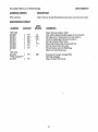
3.10 MACSbug RAM MEMORY MAP
MACSbug RAM
MACSbug RAM
•
•
.. RESET .. SSP ........
.. RESET .. PC .........
.. BUS ERROR .........
.. ILL .. ADD ...........
.. ILL .. INST ..........
.. DIVZERO ...........
CHK................
TRAP V .............
PRIV INS ............
TRACE .............
.. EML 1010 ...........
.. EML 1111 ...........
SPURIOUS
LEVEL 1
LEVEL 2
etc.
LEVEL 7
TRAP 0
TRAP 1
etc.
TRAP 15
USER INTER.
etc.
0
4
8
400
C
10
14
18
1C
20
24
28
2C
REGISTERS
PCSR
00·07
AO·A7
USSS
WINDOWS
BREAKPOINT
ADDRESSES
BREAKPOINT
CONTENTS
60
64
68
WORK RAM
57C
1/0 BUFFER
VVV
7C
80
84
6B8
1\/\/\
STACK
BC
DEFAULT
SYMBOL
TABLE
100
6SA
3FF
VVV
·NOTE: RESET SSP,PC are actually stored in ROM at addresses 20000 and 20004.
3·23
Warranty and Service
Dual Systems Control Corporation guarantees its products, under
normal use and service as described in the manufacturer's product
literature, free from defects in material and workmanship. for a
period of one year from date of shipment. This warranty is limited to
the repair or replacement of the product. or any part of the product
found to be defective at the manufacturer's factory, when retume9
to Dual Systems Control Corporation, transportation charges prepaid by customer. This warranty does not apply to any eqUipment
that has been repaired or altered, except by Dual Systems Control
Corporation, or which has been misused or damaged by accident.
In no case shall the manufacturer's liability exceed the original cost
of the product.
DUAL SYSTEMS CONTROL CORPORATION
system reliability/system integrity
720 Channing Way • Berkeley, CA 94710