1
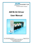
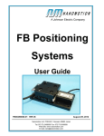
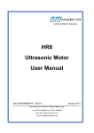
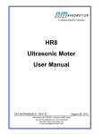
User Manual HR Motors Document No. HR00458000-00 Rev C Nanomotion Ltd. POB 623, Yokneam 20692, Israel Tel: 972-73-2498000 Fax: 972-73-2498099 Web Site: www.nanomotion.com E-mail: [email protected] 9/2015 Copyright Notice Copyright © 2012-2015 by Nanomotion Ltd. All rights reserved worldwide. No part of this publication may be reproduced, modified, transmitted, transcribed, stored in retrieval system, or translated into any human or computer language, in any form or by any means, electronic, mechanical, magnetic, chemical, manual, or otherwise, without the express written permission of Nanomotion Ltd., Mordot HaCarmel Industrial Park, Yokneam, 20692, Israel. This document contains proprietary information and shall be respected as a proprietary document with permission for review and usage given only to the rightful owner of the equipment to which this document is associated. Limited Warranty Nanomotion Ltd. provides a limited warranty on all its products. For warranty details contact your Nanomotion sales representative. Patents Nanomotion products are covered under one or more of the following registered or applied for patents. 5,453,653; 5,616,980; 5,714,833; 111597; 5,640,063; 6,247,338; 6,244,076; 6,747,391; 6,661,153; 69838991.3; 6,384,515; 7,119,477; 7,075,211; 69932359.5;1186063; 7,211,929; 69941195.5; 1577961; 4813708; 6,879,085; 6,979,936; 7,439,652; 7061158;1800356; 1800356; 1800356; 2007-533057 (pending); 2011-093431 (pending); 7,876,509; 10-2007-7009928 (pending); 200780019448.6; 7713361.9 (pending); 12/294,926 (pending); GB2008000004178 (pending); GB2009000003796 (pending); 12/398,216 (pending); GB2446428; 12/517,261 (pending); 08702695.1 (pending); 10-2009-7017629 (pending); 12/524,164 (pending); 12/ 581,194 (pending) Website www.nanomotion.com Customer Service Contact your local distributor or email Nanomotion Ltd. Technical Support Department at [email protected], with detailed problem description, additions, corrections or suggestions. Headquarters Israel Mordot HaCarmel Industrial Park HaYetsira Street, PO Box 623 Yokneam 20692 Tel: +972-73-249-8000 Fax: +972-73-249-8099 Email: [email protected] USA 1 Comac Loop, Suite 14B2 Ronkonkoma NY 11779 Tel: +1-800-821-6266 Fax: +1-631-585-1947 Email: [email protected] Revision History The following table shows the last three revisions to this document. ECO Doc Rev Date Description 752 A 9/2015 Initial release of combined HR motor user manual -- B 01/2015 Corrected typographic errors -- C 09/2015 Corrected HR2 motor stiffness value to read 1.4 - 1.8 N/µm Table of Contents Introduction . . . . . . . . . . . . . . . . . . . . . . . . . . . . . . . . . . . . . . . . . . . . . . . . . . . . . 7 CE Compliance . . . . . . . . . . . . . . . . . . . . . . . . . . . . . . . . . . . . . . . . . . . . . . . . . . . . . . . . Conventions used in this manual . . . . . . . . . . . . . . . . . . . . . . . . . . . . . . . . . . . . . . . . . . . Related Products . . . . . . . . . . . . . . . . . . . . . . . . . . . . . . . . . . . . . . . . . . . . . . . . . . . . . . . Related Documentation . . . . . . . . . . . . . . . . . . . . . . . . . . . . . . . . . . . . . . . . . . . . . . . . . . 7 7 8 8 Overview of the HR Motors . . . . . . . . . . . . . . . . . . . . . . . . . . . . . . . . . . . . . . . 10 HR Motor System. . . . . . . . . . . . . . . . . . . . . . . . . . . . . . . . . . . . . . . . . . . . . . . . . . . . . . 10 General Precautions . . . . . . . . . . . . . . . . . . . . . . . . . . . . . . . . . . . . . . . . . . . . . . . . . . . 11 Mounting and Connecting HR Motors . . . . . . . . . . . . . . . . . . . . . . . . . . . . . . . 12 Preparing the Stage Base . . . . . . . . . . . . . . . . . . . . . . . . . . . . . . . . . . . . . . . . . . . . . . . Motor Mounting Holes . . . . . . . . . . . . . . . . . . . . . . . . . . . . . . . . . . . . . . . . . . . . . . . Relation of Motor Mounting Base to Ceramic Strip . . . . . . . . . . . . . . . . . . . . . . . . . Stage Carriage Design Guidelines. . . . . . . . . . . . . . . . . . . . . . . . . . . . . . . . . . . . . . Bonding the Driving Element to the Carriage. . . . . . . . . . . . . . . . . . . . . . . . . . . . . . Motor Installation - Linear and Rotary Stages . . . . . . . . . . . . . . . . . . . . . . . . . . . . . . . . Mounting HR1 and HR2 Motors on Linear Stage. . . . . . . . . . . . . . . . . . . . . . . . . . . Mounting HR1 and HR2 Motors on Rotary Stage . . . . . . . . . . . . . . . . . . . . . . . . . . Mounting HR4 and HR8 motors on Linear Stage. . . . . . . . . . . . . . . . . . . . . . . . . . . Electrical Connections . . . . . . . . . . . . . . . . . . . . . . . . . . . . . . . . . . . . . . . . . . . . . . . . . . Grounding the Motor . . . . . . . . . . . . . . . . . . . . . . . . . . . . . . . . . . . . . . . . . . . . . . . . Connecting a Standard Motor Cable . . . . . . . . . . . . . . . . . . . . . . . . . . . . . . . . . . . . Ultra High Vacuum Motor Connection . . . . . . . . . . . . . . . . . . . . . . . . . . . . . . . . . . . Motor Conditioning. . . . . . . . . . . . . . . . . . . . . . . . . . . . . . . . . . . . . . . . . . . . . . . . . . . . . Maintenance. . . . . . . . . . . . . . . . . . . . . . . . . . . . . . . . . . . . . . . . . . . . . . . . . . . . . . . 13 13 15 16 17 19 20 21 23 25 25 26 27 27 28 HR Motor Specifications and Dimensions . . . . . . . . . . . . . . . . . . . . . . . . . . . 30 General Information . . . . . . . . . . . . . . . . . . . . . . . . . . . . . . . . . . . . . . . . . . . . . . . . . . . . 30 HR Motor Specifications . . . . . . . . . . . . . . . . . . . . . . . . . . . . . . . . . . . . . . . . . . . . . . . . 31 Thermal Envelope of Performance . . . . . . . . . . . . . . . . . . . . . . . . . . . . . . . . . 34 Stage Heat Dissipation Consideration . . . . . . . . . . . . . . . . . . . . . . . . . . . . . . . . . . . . . . EOP for HR Motors Driven by AB5 Drivers . . . . . . . . . . . . . . . . . . . . . . . . . . . . . . . . . . Example EOP Definitions. . . . . . . . . . . . . . . . . . . . . . . . . . . . . . . . . . . . . . . . . . . . . . . . Define EOP for AB5 Driver in Vacuum Environment, Brake_On Mode . . . . . . . . . . Example - Define EOP for AB5 Driver in Vacuum Environment, Brake_Off Mode . 34 37 38 38 39 Appendix. . . . . . . . . . . . . . . . . . . . . . . . . . . . . . . . . . . . . . . . . . . . . . . . . . . . . . . . 40 Vacuum Motor Baking Instructions. . . . . . . . . . . . . . . . . . . . . . . . . . . . . . . . . . . . . 40 HR1 Mechanical Drawings . . . . . . . . . . . . . . . . . . . . . . . . . . . . . . . . . . . . . . . . . . . 43 HR2 Mechanical Drawings . . . . . . . . . . . . . . . . . . . . . . . . . . . . . . . . . . . . . . . . . . . 45 v HR4 Mechanical Drawings . . . . . . . . . . . . . . . . . . . . . . . . . . . . . . . . . . . . . . . . . . . 47 HR8 Mechanical Drawings . . . . . . . . . . . . . . . . . . . . . . . . . . . . . . . . . . . . . . . . . . . 49 vi INTRODUCTION This user manual provides general instructions for Nanomotion HR motors. These motors can be controlled and drive by different Nanomotion Drivers as well as by user developed hardware. During planning and design of the motion system refer to both this manual and the user manual for the Nanomotion Driver being used. CE COMPLIANCE Nanomotion HR motors comply with the following directives: • • • • • • Safety: IEC 61010-1:1990 EMC: 89/336/EEC as amended by 92/31/EEC and 93/68/EEC Harmonized Standards to which conformity is declared: EN 50081- 2:1993/EN 55011:1991 Generic Emission Standards Class A for radiated emission and Class B for conducted emission. EN 50082- 2:1995 Generic Immunity Standard CONVENTIONS USED IN THIS MANUAL Throughout this manual commands are shown in BOLD and parameter values are shown in italics. The following indicate information that is relevant to use and operation of the equipment. NOTE: Notes provide additional information that is not included in the normal text flow CAUTION: Caution provides information about actions that will adversely affect system performance. Document No. HR00458000-00 Rev C 7 Related Products BKM Best Known Methods: BKMs provide recommended actions or procedures. Danger: Indicates actions that will cause damage to equipment or are a danger to personnel RELATED PRODUCTS The following table lists Nanomotion products covered by these instructions. Product Part Number AB1A Driver AB1A458000-XX AB1A-3U AB3U458000-XX AB1B Driver AB1B458000-XX AB2 Driver AB02458000-XX AB4 Driver AB04458000-XX AB5 Driver AB05458000-XX XCD Motherboard XCDH150100-XX XCD HR1 Controller Driver XCD-HR1-BD-XX XCD HR2 Controller Driver XCD-HR2-BD-XX XCD HR4 Controller Driver XCD-HR4-BD-XX XCD HR8 Controller Drive XCD-HR8-BD-XX XCD HR16 Controller Driver XCD-HR16-BD-XX RELATED DOCUMENTATION The following table lists related Nanomotion guides and manuals. Document Document number AB1A Driver User Manual AB1A458000 AB1A-3U Driver User Manual AB3U458000 AB1B Driver User Manual AB1B458000 Document No. HR00458000-00 Rev C 8 Related Documentation Document Document number AB2 Driver User Manual AB02458000 AB4 Driver User Manual AB04458000 AB5 Driver User Manual AB05458200 XCD-HR1,-HR2, -HR4 Controller Driver User Manual XCDH458000 XCD-HR8, -HR16 Controller Driver User Manual XCDH458002 Document No. HR00458000-00 Rev C 9 OVERVIEW OF THE HR MOTORS The HR series of motors are high precision ceramic motors. The HR motors combine unlimited stroke with high position resolution, in compact dimensions. The motors are used in applications such as microscopy, precision motion, robotics, etc. The HR motors are available in versions that are compatible with vacuum and ultra-high vacuum operating environments.These applications include wafer inspection and metrology, scanning stages and lithography When working with a Nanomotion AB05 Driver the motors provide a linear response to the input voltage. The operation of the motor and Driver resembles that of a DC-motor driven by a voltage amplifier. Motor Controller/Driver HR1 AB1A, AB1A-3U, AB02, AB4, AB5/51 XCD-HR1 HR2 AB1A, AB1A-3U, AB02, AB4, AB5/51 XCD-HR2 HR4 AB1A, AB1A-3U, AB02, AB4, AB5/51 XCD-HR4 HR8 AB1A, AB1A-3U, AB02, AB4, AB5/51 XCD-HR8, XCD-HR16 HR MOTOR SYSTEM An HR motor is part of a motion system (Figure 1) consisting of the following parts: • • • HR Motor • Standard motors provided with a 3m shielded and jacketed cable • Vacuum motors provided with a 3m shielded cable • UHV motors provided with 0.5m flying leads (3 wires) Ceramic • Driving Strip - for linear applications • Driving Ring/Disk - for rotary applications. Driver • AB01, AB02, AB04 Driver with a Controller with a servo rate >8KHz Document No. HR00458000-00 Rev C 10 General Precautions • AB05 Driver with standard Controller with servo rate > 4KHz (20KHz recommended). Some standard off-the-shelf controllers have been checked to provide high performance with Nanomotion motors. Consult Nanomotion for specific manufacturers and controllers. • • XCD Controller/Driver or compatible third party driver Optional encoder to provide position feedback Figure 1: Closed-Loop HR Motor Drive System Block Diagram GENERAL PRECAUTIONS When handling HR motors observe the following precautions: • • • • • • The motor has high voltage inside. Do not open Do not apply electric power unless the motor is mounted and preloaded. Do not immerse the motor in any solvent or cleaning agent. Use only a clean cloth to wipe the motor. Be sure that the motor, and especially the motor's tips, are not subjected to mechanical shocks. Do not operate Nanomotion vacuum and high-vacuum motors in air pressure between 0.1 torr and 200 torr. Document No. HR00458000-00 Rev C 11 MOUNTING AND CONNECTING HR MOTORS For optimal motor performance, it is recommended to use only the Ceramic Drive Strips provided by Nanomotion. These Ceramics have been specifically designed to work with Nanomotion motors. Substituting this strip with any other material might reduce motor performance or damage the motor. Use of Ceramic Drive Strips from suppliers other than Nanomotion voids the motor warranty. Figure 1: Example Mounting Base (image is for reference only) Document No. HR00458000-00 Rev C 12 Preparing the Stage Base PREPARING THE STAGE BASE The application's HR motor and Carriage are mounted on the Stage base. The form of the Base and the Carriage are application dependent. However, some basic rules are applicable to all designs to ensure optimal performance. It is critical that the stiffness of the stage perpendicular to the direction of carriage travel is >50N/µm Motor Mounting Holes The HR1 and HR2 motors require a mounting base (Figure 2) with slots for the motor mounting screws. The slots provide the ability to apply preloading when mounting the motor. The motor tension against the ceramic strip is set using a spacer during the mounting process. All dimensions in this document are in millimeters unless otherwise specified. Isometric drawings use European standard display. Document No. HR00458000-00 Rev C 13 Preparing the Stage Base Figure 2: Mounting Base Dimensions for HR1 and HR2 Motors The mounting base for the motors must be an integral part of the stage baseplate. The HR4 and HR8 motors have a built in preload setting. Therefore the motors are mounted in a fixed position (Figure 3). Document No. HR00458000-00 Rev C 14 Preparing the Stage Base Figure 3: Mounting Base Dimensions for HR4 and HR8 Motors Relation of Motor Mounting Base to Ceramic Strip The ceramic strip must be mounted perpendicular to the mounting base as specified in Figures 2 and 3. The size and position of the ceramic strip should follow the dimension specified in Figure 4 and Table 3-1. Figure 4: Ceramic Position Document No. HR00458000-00 Rev C 15 Preparing the Stage Base Table 3-1: Dimensions from Motor Mounting Base to Ceramic A B HR1 2 mm 6 mm HR2 2 mm 11 mm HR4 3.5 mm 12 mm HR8 3.5 mm 21 mm Stage Carriage Design Guidelines The Carriage is the customer designed portion of the Stage that is moved by the HR motor. The interface between the Stage and the motor is the Ceramic Strip. The designer must limit the Stage motion to prevent a loss of contact between the motor tip(s) and the Ceramic Strip on the Carriage. The provided ceramic driving plate should not exceed the stage. It must be supported by a solid even backing along all its entire length to avoid breaking when motor is pressed against it. No holes or grooves are allowed on the ceramic mounting surface or at a proximity to the surface to allow smooth operation of the motor. the carriage motion should be limited to assure that motor tips do not lose contact with the ceramic at any point. Hard limits are recommended on top of any soft or electrical limits (see Figure 5) at the ends of the carriage movement. Figure 5: Distance between motor tip and edge of Ceramic Drive Strip For example, design mechanical limiters so that the Driving Strip extends at least 5 mm beyond the carriage's maximum positive or negative travel. The actual distance is dependent on the application and usage of the motor. Document No. HR00458000-00 Rev C 16 Preparing the Stage Base Bonding the Driving Element to the Carriage The Driving Strip provides the interface between the motor's tips and the Carriage. It must present a solid surface to ensure accuracy of movement as well as long operating life. Mounting Ceramic Element on Linear Stage The Driving Strip is supplied with double-sided tape along one surface for mounting to the carriage. • • The Drive Strip must be fully supported by the carriage along its full length and width. The Drive Strip must be secured to the Carriage at its center with epoxy to ensure rigidity along its length. The instructions given in this section refer to the standard Ceramics provided by Nanomotion. Nanomotion does not guarantee performance attained by strips purchased from other sources. 1. Clean the surface of the carriage where the Driving Strip will be bonded. Use a suitable agent such as Isopropyl Alcohol, Ethanol, Acetone, or Methanol. 2 Peel off the self-adhesive backing paper on the Ceramic. The self adhesive tape is compatible with high-vacuum applications. . Ensure there are no folds or large bubbles in the adhesive layer before mounting the ceramic to the stage. 3 Position the Driving Strip on the drive surface of the carriage and press along its length. Ensure that bubbles or wrinkles do not form between the drive strip and mounting surface. 4 Apply epoxy adhesive at the center of the Ceramic. The epoxy should be applied along the joint of the ceramic strip and the carriage over a minimum of 5mm (Figure 6, Figure 7). Use one of the following or a compatible adhesive: • • Emerson & Cuming Ecobond 24, for vacuum applications 3M 2216 epoxy or Arldite Radite, for non-vacuum applications Document No. HR00458000-00 Rev C 17 Preparing the Stage Base Figure 6: Securing the Ceramic to the Stage When attaching ceramic strips with a width (dimension A) of 6mm or less (HR1, EDGE, and EDGE 4X motors) apply epoxy on both the upper and lower surfaces. Figure 7: Epoxy Coverage on Flat and 90 Degree Joints Ensure that the epoxy contacts the ceramic plate and the stage carriage. Ensure that it does not flow onto the Ceramic Strip’s front surface 5 Allow the required time period for curing according to the Epoxy manufacturer specifications. 6 Mount the Carriage on the Stage. Document No. HR00458000-00 Rev C 18 Motor Installation - Linear and Rotary Stages Mounting Ceramic Ring on Radial Stage 1. Verify that all parts are clean 2 Spread an even layer of epoxy on the inner rim of the ceramic ring. 3 Slide the ceramic ring onto the flange and turn it CW and CCW to spread the epoxy evenly. Figure 8: Mounting Ceramic Ring on Radial Flange 4 Use a dial indicator with a resolution of 2 micron or less to center the ring to 10micron runout. 5 Allow the required time period for curing according to the Epoxy manufacturer specifications. MOTOR INSTALLATION - LINEAR AND ROTARY STAGES After the Carriage is mounted on the Base the motor can be mounted. HR motors can be mounted on either of the motor’s two flat surfaces. The primary consideration for HR1 and HR2 motors is the cable routing. To install HR motors use the following items: • Spacer - It is necessary to use a spacer to mount HR1 and HR2 motors on both linear (Figure 9) and rotary stages. The spacer provides the motor’s pre-load. Document No. HR00458000-00 Rev C 19 Motor Installation - Linear and Rotary Stages Figure 9: Spacer - 1.8mm thickness, PN: MSP1J02001-11 • • Allen wrench - M3 for HR1 and HR2 motors, and M4 for HR4 and HR8 motors. Screw and washer - M3 for HR1 and HR2 motors, and M4 for HR4 and HR8 motors. Screw length should be sufficient to pass the base and contact least 1/ 2 the depth of the motor body. If the screw protrudes from the motor. care should be taken that it does not interfere with the movement of other stage parts such as the stroke of the upper axis. Mounting HR1 and HR2 Motors on Linear Stage Nanomotion HR1 and HR2 motors do not have pre-load screws. The pre-load is set by using a 1.8mm thick spacer (P.N. MSP1J02001-11). 1. Set the motor in place and finger-tighten the four mounting screws (M3) and washers. Apply a small amount of blue Loctite to the screws before mounting. The motor should be secure but able to move. 2 Position the spacer supplied with the motor between the motor and the Drive Strip on the carriage. Document No. HR00458000-00 Rev C 20 Motor Installation - Linear and Rotary Stages Figure 10: Spacer Set Between Motor and Ceramic Strip 3 Hold the motor against the spacer, applying even pressure on both sides of the motor. 4 Using a diagonal sequence, tighten the four mounting screws (M3). Ensure that the motor does not move during this process. 5 Apply a torque of 0.5 to 0.7 Nm to each screw and remove the spacer. 6 Perform motor conditioning according to Motor Conditioning, on page 27. Mounting HR1 and HR2 Motors on Rotary Stage Because a rotary stage presents an arc to the motor, mounting and preloading the motor requires additional steps. Nanomotion stages are manufactured with an alignment ridge to keep the motor perpendicular to the Document No. HR00458000-00 Rev C 21 Motor Installation - Linear and Rotary Stages rotary element. For rotary stages with a diameter of 60-80mm two holes are added to the base. For unique rotary applications or assistance contact your Nanomotion engineering/ sales representative. 1. Set the motor in place and finger-tighten the four mounting screws. The motor should be secure but able to move. 2 Ensure that the motor is set against the alignment ridge of the base. • For rotary elements a. Cut the flat spacer (P.N. MSP1J02001-11) in half between the two arms. b. Slide each half of the spacer from the opposite sides of the motor until they touch the motor tip. Figure 11: Flat Spacers Positioned Next to Motor Tip (encoder not shown) c. Push the motor against the spacers and tighten the screws. d. Remove the spacers and perform motor conditioning according to Motor Conditioning, on page 27 Document No. HR00458000-00 Rev C 22 Motor Installation - Linear and Rotary Stages • For rotary element with a diameter of 60-80mm a. From the bottom of the stage set the spacer (PN: FBR0600001-00) in the two holes. It may be necessary to move the motor slightly. BKM If there is no room to set the block spacer from the bottom of the stage, cut the 1.8mm spacer in half between the arms. Slide each half of the spacer from the side of the motor until they touch the motor tip b. Push the motor against the pins and tighten the mounting screws. Figure 12: Relation of HR Motor, Spacer Pins and Ceramic Ring (encoder not shown) c. Remove the spacers and perform motor conditioning according to Motor Conditioning, on page 27. Mounting HR4 and HR8 motors on Linear Stage Nanomotion HR4 and HR8 motors have preload screws. The motors are supplied with the preload screws in the locked position and ready for mounting on the stage. 1. Ensure that the two preload screws are turned fully CCW. Document No. HR00458000-00 Rev C 23 Motor Installation - Linear and Rotary Stages Figure 13: Preload Screw Turned CCW 2 Set the motor in place and finger-tighten the four mounting screws (M4) and washers. Apply a small amount of blue Loctite to the screws before mounting. The motor should be secure but able to move. 3 Press the motor so that the motor tips are against the Drive Strip. 4 Using a diagonal sequence, tighten the four mounting screws (M3). Ensure that the motor does not move during this process. 5 Apply a torque of 0.5 to 0.7 Nm to each screw. 6 Turn the Preload screws CW to load the motor tips. Document No. HR00458000-00 Rev C 24 Electrical Connections Figure 14: Preload Screws turned CW to Load the Motor Tips 7 Perform motor conditioning according to Motor Conditioning, on page 27. ELECTRICAL CONNECTIONS The motor requires two electrical connections. • • System ground Power and control cable Grounding the Motor Nanomotion motors must be grounded to maintain electrical continuity with the Driver and ensure electrical safety for the system and users. Failure to connect the motor to the system ground is a hazard to personnel safety and equipment operation. 1. Prepare a grounding wire. • • • Terminal connector minimum 18 AWG wire maximum length of 2 meter 2 Attach the ground wire’s terminal connector between the two star washers and tighten. 3 Connect the other end of the ground cable to the system ground. Document No. HR00458000-00 Rev C 25 Electrical Connections Connecting a Standard Motor Cable Nanomotion guarantees proper Driver and motor performance only when a Nanomotion standard cable is used. Consult Nanomotion before making any changes to cable lengths. • • The Motor-Connected interlock is available on Nanomotion standard motor connector. It disables high voltage on the bare Driver connector, when the motor is disconnected from the Driver. Nanomotion's motors run at a resonant frequency and are sensitive to the capacitance of the electrical circuit. Changing cable length affects the total capacitance and will affect motor performance. Refer to user manual for the installed Driver for maximum allowed cable length. The Driver selected for the application must be tuned to the motor used on the application. Failure to tune the Driver to the motor may cause damage to Driver. Changing the length of the motor cable will change the cable’s impedance, requiring retuning of the Driver. • • • Nanomotion supplies motors with specific low capacitance cables Standard motors: 210pF/meter Vacuum motors: 43pF/meter Standard and vacuum motors have an interconnect cable with a 9 pin D-type female connector. The following image and table provide pinout information Figure 15: Motor Connector Pin Function Description 1 GND System ground 2 N.C. with AB1A Driver - Phase 3 Motor-Up White wire - High voltage input 4 Motor-Common Black wire - High Voltage input for AB1A, GND for AB5 AB2 and AB4 drivers as well as XCD Controller/Drivers 5 Motor-Down Red wire - High voltage input Document No. HR00458000-00 Rev C 26 Motor Conditioning Pin Function Description 6 Motor-Connected short pin 6 to pin 1 - enables Driver. Safety input Open on pin 6 - disables the Driver. 7 GND System ground - Connected to connector hood 8 N.C. Not connected 9 N.C. Not connected Ultra High Vacuum Motor Connection The HR motors designed for ultra-high vacuum operation do not have an outlet cable or a connector. Instead, there are 3 TFE jacketed wires extending outside the motor allowing the user to connect the motor to application specific hardware. The pinout for the three wires is the same as for standard motors: • • • black wire - common white wire - up red wire - down Note that the safety interlock on pin 6 is not available with this three wire connection and should be added by the customer. MOTOR CONDITIONING Before conditioning the motor refer to the user manual for the Driver used in the application for the instructions on how to complete the interconnections of the motor, Driver, and servo controller. Conditioning of the motor is important to stabilize the motor’s dynamic performance and balance the motor heat dissipation. However, conditioning should be performed any time a motor has been assembled on the stage, or its pre-load released. Nanomotion supplies clean V and UHV motors, yet the bake-out is required in order to remove residual contaminants and absorbed humidity from the motors and other system components. Refer to the Nanomotion Vacuum and Ultra High Vacuum Motors Bake-out Procedure, Document number HR00458001 Perform conditioning as follows when using Nanomotion AB05 Driver: • • Set the conditioning procedure to cover the whole expected operated travel of the ceramic drive strip. Run the stage repetitively from end to end in closed-loop at: • velocity of 100 mm/sec. Document No. HR00458000-00 Rev C 27 Motor Conditioning • • Acceleration - <1.5 m/sec2 Duty cycle and duration Driver Duty cycle Duration AB1, AB2, AB4 50% 4 hrs AB5 25% 8 hrs Before operating the motor verify the following: • • • • • Make sure the Driver is set to operate with the motor. All motors are properly mounted and pre-loaded. Mechanical screws lock all connectors. The external power supply is capable of supplying the required power consumption of the Driver. There is no command from the Controller to the motor when turning the power on. For AB5 or XCD in high resolution mode run the motor for 8 hours at 25% DC at the same conditions when using XCD controller driver it is recommended to condition the motor in standard mode even if the application uses high resolution mode. Never operate the motor during vacuum pumping or at pressure of 0.1 to 200 torr (Corona region) to avoid electric brake through air. When conditioning is completed, carefully clean the Ceramic with a lint free cloth and isopropyl Alcohol IPA. Do not remove the motor from the base during cleaning. General remarks: • • Conditioning should be repeated if the motor is removed from the stage and then reinstalled or if the preload is released. Do not condition the motor in a vacuum environment. Maintenance The HR motors have no user repairable or replaceable parts. However, the user might need to clean the motor tips and ceramic drive plane from time-totime. The frequency of cleaning depends on the operating environment and type of operating conditions. Do not remove the cover of the HR motor. The motor has high voltage inside when power is applied. Document No. HR00458000-00 Rev C 28 Motor Conditioning To clean the motor tips and ceramic plane 1. Remove power from the motor. 2 Loosen the motor mounting screws. For HR4 and HR8 motors, turn the pre-load screw fully CCW. 3 Wipe the Drive Strip and motor tips using a piece of lint free cloth and isopropyl alcohol or ethanol. 4 Reset the motor according to the procedures in Motor Installation Linear and Rotary Stages, on page 19. 5 Perform Motor Conditioning, on page 27. Document No. HR00458000-00 Rev C 29 HR MOTOR SPECIFICATIONS AND DIMENSIONS This chapter provides mechanical, and electrical specifications for HR motors and mechanical drawings to provide motor dimensions. GENERAL INFORMATION These specifications apply to the standard motor driven by the AB1A Driver Box. The motor features a linear voltage response. The motor and driver can be modeled as a DC-motor with friction driven by a voltage amplifier, as illustrated in the following diagram. Figure 1: Block Diagram of the Motor and Driver Where: • • • • • • • Vin - Command to the driver -10 to +10 [V] Kf - Force constant [N/V] Offset - Starting voltage [V] Kfv - Velocity damping factor (similar to back EMF) [N x sec / m] Vel - Motor velocity [m/Sec] M - Moving mass [kg] S - Laplace variable [1/sec] Document No. HR00458000-00 Rev C 30 HR Motor Specifications Figure 2: Typical Motor Sub-system The figure above shows a typical HR Driver/Motor Sub-system. A command voltage of ±10V is applied to the driver. The driver then generates a 39.6Khz sine wave (V motor) whose amplitude is a function of the command voltage. The sine wave drives the HR4 motor. HR MOTOR SPECIFICATIONS Table 1: Performance Specifications Specification HR1 HR2 HR4 HR8 Maximum Allowable Velocity 250 mm/sec 250 mm/sec 250 mm/sec 250 mm/sec Dynamic Stall Force 3.5 to 4.5 N 7 to 9 N 15-18 N 30-36 N 3.5 N 7N 14 N 28 N 0.8 - 1 1.4 - 1.8 2.3 - 2.8 3.3-3.8 N/µm N/µm N/µm N/µm 18 N 36 N 72 N 144 N Static Holding Force Reference value Non-Energized Stiffness Nominal Preload on Stage Kf Driver and command dependent Kfv Offset Nominal Lifetime Document No. HR00458000-00 Rev C 0.5 - 1 N/Volt 1-2 N/volt 2-4 N/Volt 4 N/Volt 12 to18 24 - 36 60-72 120-144 N·sec/m N·sec/m N·sec/m N·sec/m 1 - 2 V - Driver dependent 20,000 hours under nominal operating conditions 31 HR Motor Specifications Table 2: Electrical Specifications Specification Maximal Voltage 39.6 KHz, sine wave Typical motor current at max voltage (Cable length dependent) Maximum Power Consumption HR1 HR2 HR4 HR8 280 Vrms 280 Vrms 270 Vrms 270 Vrms 120 250 320 600 mA rms mA rms mA rms mA rms 5W 10 W 20 W 40 W Table 3: Environmental Specifications Specification HR1 HR2 Ambient Temperature: HR4 HR8 0 - 50º C Storage: -40 to +70º C Humidity: 0 - 80% non-condensing Vacuum level for highvacuum motors 1e-7 torr (guaranteed only after baking) Vacuum level for ultrahigh-vacuum motors 1e-10 torr (guaranteed only after baking) Maximum Baking Temperature for vacuum motors 120º C for standard motors 140º C - for ultrahigh vacuum motor Do not operate Nanomotion vacuum and high-vacuum motors in air pressure between 0.1 torr and 200 torr. Table 4: Physical Dimensions Specification HR1 HR2 HR4 HR8 Length: 40.5 mm 40.5 mm 42 mm 41.9 mm Width: 25.7 mm 25.7 mm 46.6 mm 46.6 mm Document No. HR00458000-00 Rev C 32 HR Motor Specifications Table 4: Physical Dimensions Specification HR1 HR2 HR4 HR8 Height: 8 mm 12.7 mm 15 mm 23.8 mm Weight - standard motor 20 gr. 40 gr. 73 gr. 120 gr.- Weight - high & ultrahigh vacuum motors 30 gr. 30 gr. 60 gr. 170 gr.- Document No. HR00458000-00 Rev C 33 THERMAL ENVELOPE OF PERFORMANCE Motor operating temperature is a result of the balance between heat generation and heat dissipation. • • The heat generation depends on motor's work regime (Driver command level). The heat is dissipated through the following heat transfer mechanisms: • conduction • radiation • convection - negligible in a vacuum environment). The heat dissipation mechanisms should be able to dissipate the heat generated in order to avoid overheating. The EOP gives the user the tools to assess the permitted operating conditions (for set ambient temperature and command, deriving the duty cycle and maximal continuous operation that assures safe operation). The user can either operate the motor for an extended period of time at a specific duty cycle or alternatively, can operate the motor for a continuous time period specified under Maximal Continuous Operation Time. After the continuous operation is completed, the Driver must be disabled to cool down the motor for 400 sec in air and for 700 sec in vacuum environment. The duty cycle is the ratio of the operation time and the total work cycle (operation time + idle time). When operating the motor with the AB5 Driver continuously in Brake-Off Mode, the motor consumes power at all times, even when the control command voltage is 0 (zero) thus the time at 0 command is accounted in the heating process and reduces the thermal EOP. Upon operating a motion system in vacuum, it is expected that the Coefficient of Friction of the bearing structure will increase. This may require changing the system operation point on the thermal EOP curves. STAGE HEAT DISSIPATION CONSIDERATION The motor heat dissipation mechanism is by convection and radiation to the motor case, and by conduction through motor's tips. Hence, the motor and the Ceramic bases, must both be thermally designed to dissipate 2W each (per motor's 'finger tip'), with maximum temperature rise of 15 C. Thermal EOP for HR1 Motor Driven by AB1A, AB2 AB4 Drivers Document No. HR00458000-00 Rev C 34 Stage Heat Dissipation Consideration Figure 7 illustrates motor velocity as a function of the applied Driver command voltage. Allowing up to 30 mm/sec variations, use it as a reference and as a guideline for expected motor performance: Figure 1: Figure 7: Motor Velocity vs. Command The motor operates horizontally at room temperature and low duty cycle (< 10%). It interfaces with the Ceramic (according to Nanomotion Specifications) and a cross-roller high quality slide. Figure 8 are designed to help the user determining the correct envelope of performance and avoid overheating and damaging the motor. Figure 2: Figure 8: Motor Force vs. Velocity at the Various Work Regimes (a-g) Document No. HR00458000-00 Rev C 35 Stage Heat Dissipation Consideration Table 1: EOP Table for HR Motors Driven by AB1A, AB2, AB4 Air 25°C Curve Duty Cycle [%] Air 50°C Maximal Continuous Operation time [sec] Duty Cycle [%] Vacuum Maximal Continuous Operation time [sec] Maximal Continuous Operation time [sec] Duty Cycle [%] a 100 100 100 b 100 100 44 184 c 100 92 137 26 107 d 100 62 93 17 72 e 78 87 47 70 13 55 f 56 62 33 50 9 39 g 50 56 30 45 8 35 An Example for Defining the EOP for AB1A Driver in Vacuum Environment An example for using the graph and table for the AB1A Driver: A vacuum application requires 1.25N at a velocity of 100mm/sec. The graph shows that this point of operation corresponds to the curve d. The table shows that curve d and a vacuum environment require that a duty cycle of 17% will not be exceeded and the maximum continuous operation time is limited to 72 seconds. Document No. HR00458000-00 Rev C 36 EOP for HR Motors Driven by AB5 Drivers EOP FOR HR MOTORS DRIVEN BY AB5 DRIVERS The AB5 drivers are preferable for a perfect servo tracking and/or very low ripple constant velocity. Refer to the AB5 Drivers User Manual, AB05458200. The AB5 unique features result in the motor consuming more power and in a lower EOP, compared to the EOP for a motor operating with the AB1A Driver. Figure 9 illustrates motor velocity as a function of the applied AB5 Driver command voltage. Allowing up to 30 mm/sec variations, use it as a reference and as a guideline for expected motor performance: Figure 3: Velocity vs. Command Using the AB5 Driver This graph and the following table are designed to help the user determine the correct envelope of performance and avoid overheating and damaging the motor. Figure 4: Force vs. Velocity Using the AB5 Driver at the Various Work Regimes Document No. HR00458000-00 Rev C 37 Example EOP Definitions . Table 2: EOP Table for HR Motors Driven by the AB5 Driver Air 25°C Curve Duty Cycle Brake_ Off [%] Vacuum Duty Cycle Continuous Duty Cycle Continuous Brake_On [%] Operation [sec] Brake_On [%] Operation [sec] 0÷a 100 100 56 500 b 100 100 54 450 c 100 100 45 280 d 100 100 33 170 e 100 100 23 100 f 53 58 170 12 66 g 33 48 77 10 44 h 17 28 32 6.5 25 In the Brake_Off Mode the full advantage of the AB5 Driver is enabled giving a linear response, best tracking and low velocity performance. Using this mode, the motor operates continuously, even at 0 command and special attention must be given to maintain the work regime within the permitted Duty Cycle and Maximal Continuous Operation Time. Once the operation time has reached the Maximal Continuous Operation Time, even at Brake_Off Mode without motion the Driver must be disabled to allow the motor to cool down for at least 400 seconds in air and 700 sec in vacuum environment. EXAMPLE EOP DEFINITIONS Define EOP for AB5 Driver in Vacuum Environment, Brake_On Mode A vacuum application requires 1N at a velocity of 80mm/sec and the motor is disabled when stand still (Brake_On Mode). The graph shows that this point of operation corresponds to the curve e. In Figure 4, AB5 in Brake_On Mode shows that curve e and a vacuum environment require that a duty cycle of 13% will not be exceeded and the maximum continuous operation time is limited to 90 seconds. Alternatively AB5 can be used giving duty cycle and continuous operation of 23% and 100 sec respectively. The same conditions under Air at 25° C will result in 100% Duty Cycle and unlimited continuous operation. Document No. HR00458000-00 Rev C 38 Example EOP Definitions Example - Define EOP for AB5 Driver in Vacuum Environment, Brake_Off Mode When Brake_Off Mode is used under vacuum conditions the motor will overheat at any duty cycle, if operated for a prolong time. To calculate the max operation time, use curve 0÷a for time at 0 command and the operation curve for the operating time according to the following formula: Tmax=(max continues operation at the operation regime) * DC + (max continuous operation under regime a)*(1-DC). If operating under curve c using AB5 in a duty cycle of 10%, the total operation time is: Tmax=150 *0.1 +230*(1-0.9)=222 sec Once Tmax is reached, the Driver should be disabled for a period of 700 sec. Document No. HR00458000-00 Rev C 39 APPENDIX This appendix provides the following information. • • Vacuum motor baking instructions Mechanical Drawings • HR1 Mechanical Drawings on page • HR2 Mechanical Drawings on page • HR4 Mechanical Drawings on page • HR8 Mechanical Drawings on page 43 45 47 49 VACUUM MOTOR BAKING INSTRUCTIONS This manual is intended to guide the user in performing the bake-out procedure on Nanomotion (NM) vacuum (V), vacuum non-magnetic (VN) and ultra high vacuum (UHV) motors, prior to their operation. The bake-out procedure should be performed in a vacuum oven, either on motors alone or, on complete systems with motors mounted, under approval of the stage manufacturer. Nanomotion supplies clean V, VN and UHV motors, yet a bake-out procedure is required, in order to remove residual contaminants and adsorbed humidity from the motors and other system components. Nanomotion also supplies ready for use, baked motors, upon customer's request. Motors Only Procedure Nanomotion supplies both V and VN motors with a motor connector for initial operation, for instance, a burn-in procedure. These connectors are nonvacuum compatible. Therefore, in order to assure optimal motors bake-out, it is recommended to cut off the connectors before bake-out. The UHV motors are supplied with 3 flying wire leads and no connector. Nanomotion suggests performing the following steps for V, VN and UHV motors: 1. Nanomotion supplies V, VN and UHV versions of HR4 and HR8 motors with preload screws retracted. Prior to bake-out, release the motor preload screws (half turn clockwise). 2. Cut the motor connector off (for V and VN motors). 3. Short-circuit the three wire leads of the motor cable: white, black and red. 4. Place the motor in a vacuum oven. Document No. HR00458000-00 Rev C 40 5. Attain vacuum level, specified in the following table: Table 1: Bake-out Conditions Motor Type Temperature Temperature Minimal (°C) (°C) Recommended Vacuum Level without Motor with NM Motor (Torr) Connector Connector Duration (hours) V, VN 10-4 110 100(*) 24 UHV 10-4 140 N/A 24 * Bake out at 100°C may not be sufficient to achieve full motor baking. 6. Gradually raise the temperature, at a maximum rate of 4°C/min to the temperature, specified in Table 1. 7. Maintain the motor for 24 hours in the oven under the specified vacuum conditions. 8. Gradually cool down the vacuum oven at a typical rate of no more then 4°C/min. 9. After the vacuum oven has reached room temperature leave the motor for relaxation time at an ambient temperature for 48 hours, before testing or mounting the motor. 10. After 48 hours, retract motor preload screws. The motor is ready for testing or mounting. Full Systems with Motors Mounted For baking-out a full system with motors mounted, perform the following steps: 1. Disconnect the motor connector from the driver (or the LC box). 2. It is assumed that the motor connector is not the NM original connector but rather a custom connector chosen by the stage designer. Verify the pinout of the actual connector, used in the system, and identify the pins associated with the three wire leads of the motor cable: white, black and red. 3. Short-circuit connector's motor pins: • • Short circuit the pins associated with three wire leads of the motor cable: white, black and red. If the NM original connector is maintained, short circuit according to Table 2: Table 2: Motor 9 Pin D-Type Connector Description Wire Pin White 3 Black 4 Red or Orange 5 4. Place the system in a vacuum oven. 5. Perform bake-out according to step 5 on page 41 through step 9 on page 41 Multiple Motors per Axis Systems For baking-out a system, with motors mounted and connected by means of branch cables, perform the following steps: 1. Disconnect the motors from the branch cable. 2. Place the system in a vacuum oven. 3. Perform bake-out according to step 2 on page 41 through step 5 on page 42. Document No. HR00458000-00 Rev C 42 HR1 MECHANICAL DRAWINGS Dimensions for HR1 Standard and High-Vacuum Motor Document No. HR00458000-00 Rev C 43 Dimensions for HR1 Ultra-High-Vacuum Motor Document No. HR00458000-00 Rev C 44 HR2 MECHANICAL DRAWINGS Dimensions for HR2 Standard and High-Vacuum Motors Document No. HR00458000-00 Rev C 45 Dimensions for HR2 Ultra-High-Vacuum Motors Document No. HR00458000-00 Rev C 46 HR4 MECHANICAL DRAWINGS Dimensions for HR4 Standard and High-Vacuum Motors Document No. HR00458000-00 Rev C 47 Dimensions for HR4 Ultra-High-Vacuum Motors Document No. HR00458000-00 Rev C 48 HR8 MECHANICAL DRAWINGS Dimensions for HR8 Standard and High-Vacuum Motors Document No. HR00458000-00 Rev C 49 Dimensions for HR8 Ultra-High-Vacuum Motor Document No. HR00458000-00 Rev C 50