1
Maintenance and Troubleshooting Manual
Par t Number 3-9000-767Revision A
June 2011
DanielTM 3812 Liquid Ultrasonic Flow Meter
Important Instructions
Daniel Measurement and Control, Inc. (Daniel) designs, manufactures and tests products to
function within specific conditions. Because these products are sophisticated technical
instruments, it is important that the owner and operation personnel must strictly adhere both
to the information printed on the product and to all instructions provided in this manual prior to
installation, operation, and maintenance.
Installing, operating or maintaining a Daniel Product improperly could lead to serious
injury or death from explosion or exposure to dangerous substances. Comply with all
information on the product, in this manual, and in any local and national codes that
apply to the product. Do not allow untrained personnel to work with this product.
Use Daniel parts and work procedures specified in this manual.
Daniel also urges you to integrate this manual into your training and safety program.
BE SURE ALL PERSONNEL READ AND FOLLOW THE INSTRUCTIONS IN THIS MANUAL AND ALL
PRODUCT WARNINGS.
Product owners (Purchasers):
•
Select the correct product for the environment and pressures present. If you are
unsure, discuss your needs with your Daniel representative.
•
Inform and educate all personnel in the proper installation, operation, and
maintenance of this product.
•
To ensure proper performance, only informed and trained personnel should install,
operate, repair and maintain this product.
•
Save this instruction manual for future reference.
•
If you resell or transfer this product, it is your responsibility to forward this instruction
manual to the new owner or transferee.
•
ALWAYS READ AND FOLLOW THE DANIEL ULTRASONIC FLOW METER INSTALLATION,
OPERATIONS, AND MAINTENANCE/TROUBLESHOOTING MANUALS AND ALL PRODUCT
WARNINGS AND INSTRUCTIONS.
•
Use of this equipment, including this software, for any purpose other than its intended
purpose may result in property damage and/or serious personal injury or death.
•
A Return Material Authorization (RMA) number must be obtained prior to returning any
equipment for any reason.
•
Download the RMA form on the Daniel Measurement and Control, Inc. Support
Services web page by selecting the link below.
http://www2.emersonprocess.com/EN-US/BRANDS/DANIEL/SUPPORT-SERVICES/Pages/Support-Services.aspx
Product Operation Personnel (Personnel):
•
Read and understand all instructions and operating procedures for this product.
•
Install this product as specified in the Installation manual per applicable local and
national codes.
•
Follow all warnings, cautions, and notices marked on, and supplied with, this product.
•
Follow all instructions during the installation, operation, and maintenance of this
product.
•
Before opening the flameproof enclosure in a flammable atmosphere, the electrical
circuits must be interrupted.
•
To prevent personal injury, ensure that all components are in place prior to and during
operation of the product.
•
Connect all products to the proper electrical and pressure sources when and where
applicable.
•
If you do not understand an instruction, or do not feel comfortable following the
instructions, contact your Daniel representative for clarification or assistance.
•
If this instruction manual is not the correct manual for your Daniel product, telephone
Daniel at 1-713-827-6314 and Daniel will provide you with the requested manual. You
may also download the correct manual from:
http://www.daniel.com
•
Use only replacement parts specified by Daniel. Unauthorized parts and procedures can
affect this product's performance, safety, and invalidate the warranty. "Look-a-like"
substitutions may result in deadly fire, explosion, release of toxic substances or
improper operation.
•
Save this instruction manual for future reference.
D a n i e l TM M e a s u r e m e n t a n d C o n t r o l , I n c .
Daniel 3812 Liquid Ultrasonic Flow Meter
Maintenance and Troubleshooting Manual
NOTICE
THE CONTENTS OF THIS PUBLICATION ARE PRESENTED FOR INFORMATIONAL PURPOSES ONLY, AND WHILE EVERY
EFFORT HAS BEEN MADE TO ENSURE THEIR ACCURACY, THEY ARE NOT TO BE CONSTRUED AS WARRANTIES OR
GUARANTEES, EXPRESSED OR IMPLIED, REGARDING THE PRODUCTS OR SERVICES DESCRIBED HEREIN OR THEIR
USE OR APPLICABILITY. ALL SALES ARE GOVERNED BY DANIEL'S TERMS AND CONDITIONS, WHICH ARE AVAILABLE
UPON REQUEST. WE RESERVE THE RIGHT TO MODIFY OR IMPROVE THE DESIGNS OR SPECIFICATIONS OF SUCH
PRODUCTS AT ANY TIME.
DANIEL DOES NOT ASSUME RESPONSIBILITY FOR THE SELECTION, USE OR MAINTENANCE OF ANY PRODUCT.
RESPONSIBILITY FOR PROPER SELECTION, USE AND MAINTENANCE OF ANY DANIEL PRODUCT REMAINS SOLELY
WITH THE PURCHASER AND END-USER.
TO THE BEST OF DANIEL'S KNOWLEDGE THE INFORMATION HEREIN IS COMPLETE AND ACCURATE. DANIEL MAKES
NO WARRANTIES, EXPRESSED OR IMPLIED, INCLUDING THE IMPLIED WARRANTIES OF MERCHANTABILITY AND
FITNESS FOR A PARTICULAR PURPOSE WITH RESPECT TO THIS MANUAL AND, IN NO EVENT, SHALL DANIEL BE
LIABLE FOR ANY INCIDENTAL, PUNITIVE, SPECIAL OR CONSEQUENTIAL DAMAGES INCLUDING, BUT NOT LIMITED
TO, LOSS OF PRODUCTION, LOSS OF PROFITS, LOSS OF REVENUE OR USE AND COSTS INCURRED INCLUDING
WITHOUT LIMITATION FOR CAPITAL, FUEL AND POWER, AND CLAIMS OF THIRD PARTIES.
PRODUCT NAMES USED HEREIN ARE FOR MANUFACTURER OR SUPPLIER IDENTIFICATION ONLY AND MAY BE
TRADEMARKS/REGISTERED TRADEMARKS OF THESE COMPANIES.
DANIEL AND THE DANIEL LOGO ARE REGISTERED TRADEMARKS OF DANIEL INDUSTRIES, INC. THE EMERSON LOGO
IS A TRADEMARK AND SERVICE MARK OF EMERSON ELECTRIC CO.
COPYRIGHT © 2011 BY DANIEL MEASUREMENT AND CONTROL, INC., HOUSTON, TEXAS, U.S.A.
All rights reserved. No part of this work may be reproduced or copied in any form or by any means - graphic, electronic,
or mechanical – without first receiving the written permission of Daniel Measurement and Control, Inc. Houston, Texas,
U.S.A.
WARRANTY
1. LIMITED WARRANTY: Subject to the limitations contained in Section 2 herein, Daniel Measurement &
Control, Inc. ("Daniel") warrants that the licensed firmware embodied in the Goods will execute the
programming instructions provided by Daniel, and that the Goods manufactured by Daniel will be free from
defects in materials or workmanship under normal use and care and Services will be performed by trained
personnel using proper equipment and instrumentation for the particular Service provided. The foregoing
warranties will apply until the expiration of the applicable warranty period. Goods are warranted for twelve
(12) months from the date of initial installation or eighteen (18) months from the date of shipment by Daniel,
whichever period expires first. Consumables and Services are warranted for a period of 90 days from the date
of shipment or completion of the Services. Products purchased by Daniel from a third party for resale to Buyer
("Resale Products") shall carry only the warranty extended by the original manufacturer. Buyer agrees that
Daniel has no liability for Resale Products beyond making a reasonable commercial effort to arrange for
procurement and shipping of the Resale Products. If Buyer discovers any warranty defects and notifies Daniel
thereof in writing during the applicable warranty period, Daniel shall, at its option, correct any errors that are
found by Daniel in the firmware or Services or repair or replace F.O.B. point of manufacture that portion of the
Goods or firmware found by Daniel to be defective, or refund the purchase price of the defective portion of the
Goods/Services. All replacements or repairs necessitated by inadequate maintenance, normal wear and usage,
unsuitable power sources or environmental conditions, accident, misuse, improper installation, modification,
repair, use of unauthorized replacement parts, storage or handling, or any other cause not the fault of Daniel
are not covered by this limited warranty, and shall be at Buyer's expense. Daniel shall not be obligated to pay
any costs or charges incurred by Buyer or any other party except as may be agreed upon in writing in advance
by Daniel. All costs of dismantling, reinstallation and freight and the time and expenses of Daniel's personnel
and representatives for site travel and diagnosis under this warranty clause shall be borne by Buyer unless
accepted in writing by Daniel. Goods repaired and parts replaced by Daniel during the warranty period shall be
in warranty for the remainder of the original warranty period or ninety (90) days, whichever is longer. This
limited warranty is the only warranty made by Daniel and can be amended only in a writing signed by Daniel.
THE WARRANTIES AND REMEDIES SET FORTH ABOVE ARE EXCLUSIVE. THERE ARE NO REPRESENTATIONS OR
WARRANTIES OF ANY KIND, EXPRESS OR IMPLIED, AS TO MERCHANTABILITY, FITNESS FOR PARTICULAR
PURPOSE OR ANY OTHER MATTER WITH RESPECT TO ANY OF THE GOODS OR SERVICES. Buyer acknowledges
and agrees that corrosion or erosion of materials is not covered by this warranty.
2. LIMITATION OF REMEDY AND LIABILITY: DANIEL SHALL NOT BE LIABLE FOR DAMAGES CAUSED BY DELAY IN
PERFORMANCE. THE REMEDIES OF BUYER SET FORTH IN THIS AGREEMENT ARE EXCLUSIVE. IN NO EVENT,
REGARDLESS OF THE FORM OF THE CLAIM OR CAUSE OF ACTION (WHETHER BASED IN CONTRACT,
INFRINGEMENT, NEGLIGENCE, STRICT LIABILITY, OTHER TORT OR OTHERWISE), SHALL DANIEL'S LIABILITY TO
BUYER AND/OR ITS CUSTOMERS EXCEED THE PRICE TO BUYER OF THE SPECIFIC GOODS MANUFACTURED OR
SERVICES PROVIDED BY DANIEL GIVING RISE TO THE CLAIM OR CAUSE OF ACTION. BUYER AGREES THAT IN NO
EVENT SHALL DANIEL'S LIABILITY TO BUYER AND/OR ITS CUSTOMERS EXTEND TO INCLUDE INCIDENTAL,
CONSEQUENTIAL OR PUNITIVE DAMAGES. THE TERM "CONSEQUENTIAL DAMAGES" SHALL INCLUDE, BUT NOT
BE LIMITED TO, LOSS OF ANTICIPATED PROFITS, REVENUE OR USE AND COSTS INCURRED INCLUDING
WITHOUT LIMITATION FOR CAPITAL, FUEL AND POWER, AND CLAIMS OF BUYER'S CUSTOMERS.
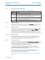
Maintenance and Troubleshooting Manual
3-9000-767 Rev A
Table of Contents
June 2011
Contents
Section 1: Routine maintenance
1.1 Meter maintenance ......................................................................................... 1
1.2 Field hydrostatic pressure testing procedures ................................................... 3
1.3
Routine maintenance ..................................................................................... 4
1.3.1
Maintenance logs and reports ........................................................................... 4
1.3.2
Pipeline cleaning maintenance.......................................................................... 7
Section 2: Troubleshooting
2.1 Meter status alarms ........................................................................................ 9
2.1.1
Check status.................................................................................................... 10
2.1.2
System alarm .................................................................................................. 10
2.1.3
Chord A and Chord B alarm............................................................................. 11
2.1.4
Field I/O alarm................................................................................................. 11
2.1.5
Validity alarm .................................................................................................. 11
2.1.6
Comms alarm.................................................................................................. 11
2.1.7
Communications............................................................................................. 11
2.2 Troubleshooting the meter ............................................................................ 12
2.2.1
Meter maintenance......................................................................................... 18
2.2.2
Unable to connect direct serial or external serial modem ................................ 24
2.2.3
Unable to connect to meter ............................................................................ 24
2.2.4
Ethernet connections ...................................................................................... 25
2.2.5
Direct serial connections ................................................................................. 25
2.3 Troubleshoot Maintenance log files and trend files .......................................... 26
Table of Contents
2.3.1
Files do not appear in workbook ...................................................................... 26
2.3.2
Microsoft® Excel® Log/Export options are not available ................................ 26
2.3.3
Maintenance Logs or Trend files are not created.............................................. 27
2.3.4
Windows® XP with Security Update................................................................ 30
i
Table of Contents
Maintenance and Troubleshooting Manual
June 2011
3-9000-767 Rev A
Section 3: Meter maintenance
3.1 Maintenance ................................................................................................. 31
3.2
Transducer field removal and installation procedure ........................................ 35
3.2.1
Transducer removal.........................................................................................36
3.2.2
Transducer installation ....................................................................................46
3.3 Transducer housing removal and installation procedure .................................. 54
3.3.1
Transducer housing removal ...........................................................................55
3.3.2
Transducer housing Installation .......................................................................58
3.4 Replace the meter electronics ........................................................................ 64
3.4.1
Replace CPU Module or Optional I/O Module (Future) .....................................65
3.4.2
Fuse Replacement ...........................................................................................67
3.4.3
Replace Backplane, I.S. Barrier or Power Supply board .....................................68
3.4.4
Acquisition Module replacement .....................................................................75
Appendix A: Conversion factors
A.1 Conversion factors per units of measurement ................................................................... 79
A.2 K Factor conversions ......................................................................................................... 80
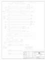
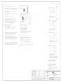
Appendix B: Engineering drawings
B.1 Daniel 3812 Liquid Ultrasonic Flow Meter drawings .......................................................... 81
Appendix C: Index
C.1 Manual index..................................................................................................................... 83
ii
Table of Contents
Maintenance and Troubleshooting Manual
3-9000-767 Rev A
List of Tables
June 2011
List of Tables
Table 2-1
Troubleshooting .............................................................................................................. 12
Table 2-2
Maintenance .................................................................................................................... 19
Table A-1
Conversion factors per units of measurement .................................................................. 79
List of Tables
iii
List of Tables
June 2011
iv
Maintenance and Troubleshooting Manual
3-9000-767 Rev A
List of Tables
Maintenance and Troubleshooting Manual
3-9000-767 Rev A
List of Figures
June 2011
List of Figures
Figure 1-2
Maintenance log collection parameters ........................................................................ 4
Figure 1-3
Trend log collection ...................................................................................................... 5
Figure 1-4
Archive log collection parameters................................................................................. 6
Figure 2-1
Meter Monitor (Summary) view .................................................................................... 9
Figure 2-2
Status Summary ........................................................................................................... 9
Figure 2-3
Meter Monitor Status Summary.................................................................................. 10
Figure 2-4
Meter Monitor (Summary) view .................................................................................. 18
Figure 2-5
Excel® 2000 Tools Menu ............................................................................................ 27
Figure 2-6
Excel® Trusted Access Setting .................................................................................... 28
Figure 2-7
Excel® 2007 Tools Menu ............................................................................................ 28
Figure 2-8
Excel® 2007 Developer tab - Macro Security .............................................................. 29
Figure 3-2
Flange stabilizers ........................................................................................................ 32
Figure 3-3
LT-10 and LT-11 transducer assembly ........................................................................ 35
Figure 3-4
Tools required ............................................................................................................ 36
Figure 3-5
Conduit removal ......................................................................................................... 37
Figure 3-6
Transmitter Electronics Enclosure and Base Enclosure security seal removal .............. 38
Figure 3-7
Transmitter Electronics Enclosure removal ................................................................. 38
Figure 3-8
Acquisition Module cable and transducer wiring ........................................................ 39
Figure 3-9
Base Enclosure removal ............................................................................................. 40
Figure 3-10
Shroud security seal removal...................................................................................... 41
Figure 3-11
Shroud removal ......................................................................................................... 42
Figure 3-12
Transducer and cable disassembly ............................................................................. 43
Figure 3-13
Feed-thru cable seal removal ..................................................................................... 43
Figure 3-14
Transducer removal .................................................................................................... 44
Figure 3-15
LT-10 Transducer and cable assembly removed from meter ....................................... 44
Figure 3-16
Upper Shroud cable seal ............................................................................................. 45
Figure 3-17
Cable removal from meter .......................................................................................... 45
Figure 3-18
LT-10 or LT-11transducer assembly ............................................................................ 46
Figure 3-19
Transducer, cable and components assembly............................................................. 47
Figure 3-20
Transducer cable installation ...................................................................................... 48
Figure 3-21
Upper Shroud Feed-thru cables................................................................................... 49
Figure 3-22
Base Enclosure installation ......................................................................................... 50
Figure 3-23
Transducer terminal block wiring................................................................................ 51
Figure 3-24
Transducer wiring and Acquisition cable reassembled ................................................ 52
List of Figures
v
List of Figures
June 2011
vi
Maintenance and Troubleshooting Manual
3-9000-767 Rev A
Figure 3-25
Lower Shroud installation............................................................................................ 53
Figure 3-26
Transducer housing removal ...................................................................................... 57
Figure 3-27
Transducer installation................................................................................................ 59
Figure 3-28
Upper Shroud Feed-thru cable seal.............................................................................. 60
Figure 3-29
Transducer terminal block wiring ................................................................................ 61
Figure 3-30
Transducer wiring and Acquisition cable reassembled ............................................... 62
Figure 3-31
Lower Shroud installation............................................................................................ 63
Figure 3-32
3810 Series electronics ............................................................................................... 64
Figure 3-33
CPU or Optional I/O Module (Future) replacement ..................................................... 65
Figure 3-34
Transmitter electronic enclosure security seals ........................................................... 66
Figure 3-35
Fuse holder cap .......................................................................................................... 67
Figure 3-36
Backplane board replacement ................................................................................... 69
Figure 3-37
I.S. Barrier board replacement ................................................................................... 71
Figure 3-38
Transmitter electronic enclosure security seals ........................................................... 72
Figure 3-39
Power Supply board replacement .............................................................................. 73
Figure 3-40
Conduit removal ......................................................................................................... 75
Figure 3-41
Transmitter Electronics Enclosure and Base Enclosure security seal removal............... 76
Figure 3-42
Transmitter Electronics Enclosure removal.................................................................. 76
Figure 3-43
Acquisition Module cable and transducer wiring ........................................................ 77
List of Figures
Maintenance and Troubleshooting Manual
Section 1: Routine maintenance
3-9000-767 Rev A
June 2011
Section 1: Routine maintenance
11
1.1
Meter maintenance
This section includes discussion of the maintenance of Daniel 3812 Liquid Ultrasonic Flow
Meters.
For reference, you may download the Daniel MeterLink Quick Start Manual from:
http://www2.emersonprocess.com/en-US/brands/daniel/Flow/ultrasonics/Pages/Ultrasonic.aspx
Daniel MeterLink may be downloaded at no charge from:
http://www2.emersonprocess.com/en-US/brands/daniel/Flow/ultrasonics/Pages/MeterLink.aspx
SURFACE TEMPERATURE HAZARD
Meter body and piping may be extremely hot or cold
Wear personal protective equipment when coming in contact with the meter. Failure to do so may result in
injury.
TRANSPORTATION HAZARD
When moving the meter, do not insert the forks of a forklift into the bore.
Inserting the forks may cause the meter to become unstable, resulting in injury or damage to the bore and
sealing face.
CRUSHING HAZARD
During meter installation or removal, always place the unit on a stable platform or surface that supports
its assembled weight.
Failure to do so could allow the meter to roll, resulting in serious injury or equipment damage.
Meter maintenance
1
Section 1: Routine maintenance
June 2011
Maintenance and Troubleshooting Manual
3-9000-767 Rev A
TRIPPING HAZARD
Clear all obstacles or obstructions from the work area when transporting, installing or removing the
meter.
Failure to clear the work area may cause injury to personnel.
ESCAPING FLUIDS HAZARD
The purchaser of the meter is responsible for the selection of Daniel components/seals and materials
compatible with the chemical properties of the measurement fluid.
Failure to select suitable meter components/seals may cause escaping fluids, resulting in injury or equipment
damage.
2
Meter maintenance
Maintenance and Troubleshooting Manual
Section 1: Routine maintenance
3-9000-767 Rev A
1.2
June 2011
Field hydrostatic pressure testing procedures
The Daniel 3812 Liquid Ultrasonic Flow Meter can be hydro-tested without any special
preparations. The transducers are not exposed to the process pressure and can remain installed
in the meter.
The liquid ultrasonic meter pressure containing parts include but are not limited to the
transducer housings. These pressure containing parts are pressure tested attached to the meter
body as a completed ultrasonic meter assembly. The hydrostatic test is verification of the
pressure containing capability of the liquid ultrasonic meter, pressure containing parts and the
seals that seal them.
LEAKAGE OR PRESSURE CONTAINING PARTS FAILURE
Use precautions to eliminate hazards to personnel in the event of leakage or failure of
the liquid ultrasonic meter pressure containing parts or failure of the test equipment
and to prevent over-pressurization during the test procedure.
Failure to do so may result in injury to personnel or cause damage to the equipment.
Field hydrostatic pressure testing procedures
3
Section 1: Routine maintenance
Maintenance and Troubleshooting Manual
June 2011
1.3
3-9000-767 Rev A
Routine maintenance
Routine maintenance operations requires adherence to all applicable regulations and laws and
safety training for personnel to perform the maintenance operations. Review your
organization’s best practices procedures before performing routine maintenance.
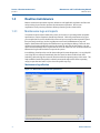
1.3.1
Maintenance logs and reports
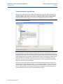
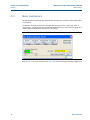
To monitor the performance health of the meter, and ensure it is operating within acceptable
specifications, routine diagnostics should be performed. Collecting a maintenance log gives
you a snapshot of the current health of the meter and you can compare the inspection reports
from previously saved logs. Use the Logs/Reports menu and click Maintenance Logs and
Reports. Daniel MeterLink displays the Maintenance Logs and Reports dialog. Choose the time
duration, log format and collection rate for the output file and click the Start button. You can
open the file immediately after it is generated or view it at a later time. It is recommended that a
Maintenance log be collected after an upset in the system.
In establishing a baseline to be used for the trending of the meter diagnostics, it is very helpful if
a set of log files are collected immediately after the meter has been installed in the field.
Preferably, collect the log files at several velocities within the operating range of the meter. This
helps establish that the flow profile is relatively constant throughout the meters operating
range (except velocities below 3 ft/sec where the profile may vary).
Maintenance log collection
Figure 1-2 Maintenance log collection parameters
4
Routine maintenance
Maintenance and Troubleshooting Manual
3-9000-767 Rev A
Section 1: Routine maintenance
June 2011
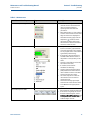
Trend maintenance log collection
Merging the results of two or more Maintenance logs into a single file, allows you to build a
historical database of the meter’s performance. Trending the logs indicates changes from the
original installation of the meter, or over time. Looking at a single inspection report, that is
either collected monthly or quarterly, can give you an indication of the meter's health.
Figure 1-3 Trend log collection
This is important since many diagnostics change slowly over time. Trending the maintenance
logs helps identify these changes and makes problems much more obvious than merely viewing
a single inspection report. The Trending feature is integral to Daniel MeterLink which allows all
important parameters to be trended. Daniel MeterLink supports trending files in a Microsoft®
Excel® workbook from multiple 3812 meter maintenance logs. Some parameters like gain,
signal level, and noise level level may show a shift over time which can be useful in detecting
changes in the meter and the installation.
Maintenance logs or Trend files to be trended must all have matching column headings. This
means the logs must be in the same units (i.e. U.S. Customary or Metric), must have the same
pressure type (i.e. gage or absolute), and must have the same time base (1/second, 1/minute,
1/hour, 1/day). If not, an error message will be displayed stating the column headings do not
match and the file will not be added to the Workbook to trend list.
Maintenance logs and reports
5
Section 1: Routine maintenance
Maintenance and Troubleshooting Manual
June 2011
3-9000-767 Rev A
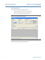
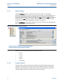
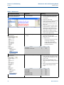
Archive log collection
Archive logs may be collected and the options include:
•
Daily log - generated every 24 hours on the Contract Hour.
•
Hourly log - generated every hour at the top of the hour.
•
Event log - collects the alarm and event log records.
Figure 1-4 Archive log collection parameters
The logs may be collected in a single file or you can choose to collect one type of log. Each of the
Meter Archive logs include the Meter Configuration file.
6
Maintenance logs and reports
Maintenance and Troubleshooting Manual
Section 1: Routine maintenance
3-9000-767 Rev A
1.3.2
June 2011
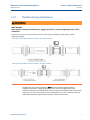
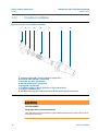
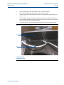
Pipeline cleaning maintenance
BURST HAZARD
Before pipeline cleaning and maintenance (“pigging operations”), remove straightening vanes or flow
conditioners.
Failure to do so may cause excessive pressure in the meter system, resulting in serious injury/ death or
equipment damage.
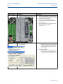
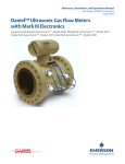
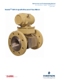
3812 Ultrasonic Flow Meter with flow conditioner for unidirectional flow
3812 Ultrasonic Flow Meter with flow conditioner for bidirectional flow
Straightening vanes or flow conditioners must be removed during pipeline cleaning
maintenance operations (“pigging operation”). if the meter run is pigged with a flow
conditioner in line, pressure may build up and cause the pipes and flanges to burst and severely
injury personnel. The excessive pressure may damage the meter or the transducer ports may
collect debris which may impede data acquisition and flow measurement.
Pipeline cleaning maintenance
7
Section 1: Routine maintenance
June 2011
8
Maintenance and Troubleshooting Manual
3-9000-767 Rev A
Pipeline cleaning maintenance
Maintenance and Troubleshooting Manual
3-9000-767 Rev A
Section 2: Troubleshooting
June 2011
Section 2: Troubleshooting
APPENDIX A:
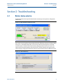
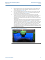
2.1
Meter status alarms
Run Daniel MeterLink and open the Meter Monitor (Summary) view to perform a diagnostics
health check.
Figure 2-1 Meter Monitor (Summary) view
If the meter is measuring flow and operating within the calibration parameters the Meter Status
LED is green. If the Meter Status LED is red, an active alarm exists that requires you to take
corrective action. Click the Check Status button to display the Status Summary screen. The
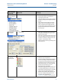
alarms are shown with the primary causes listed first. Click the question mark next to the
alarm to display a help topic related to the alarm and recommended actions to resolve the issue.
Figure 2-2 Status Summary
Meter status alarms
9
Section 2: Troubleshooting
Maintenance and Troubleshooting Manual
June 2011
2.1.1
3-9000-767 Rev A
Check status
Click the Check Status button if any of the LEDs are yellow or red to see more specific
information causing the status alarm. Some alarms do not require an acknowledgement and
will clear automatically when the alarm condition goes away. Alarms that require a user to
acknowledge them will have a button to the right titled ACK. Clicking the ACK button changes
the button text to Wait and sends a request to the meter to clear the alarm. The alarm will
disappear from the Check Status dialog once the alarm actually clears.
Click the Check Status button and Daniel MeterLink opens the Status Summary dialog box that
gives a short description of all alarms present.
Figure 2-3 Meter Monitor Status Summary
B.
A.
A. Active alarm conditions from Meter Monitor page
B. Status Summary page with alarm examples
Following is a list and a brief description of the types of alarms:
2.1.2
•
System
•
Field I/O
•
Validity
•
Comms
•
Check Status
System alarm
The System alarm indicates a failure in the hardware that should be addressed by a service
technician. This includes memory checksum errors and communication errors within the
hardware. A Red LED indicates a System alarm condition. Collect a Maintenance log and an
audit/alarm log and then, contact your Daniel service representative.
10
Check status
Maintenance and Troubleshooting Manual
Section 2: Troubleshooting
3-9000-767 Rev A
2.1.3
June 2011
Chord A and Chord B alarm
Chord A and Chord B - These alarms indicate how a chord is functioning.
2.1.4
LED Color
Problem
Green
No alarms are present. Chord is operating properly.
Yellow
At least one sample in the batch caused an alarm but it did not cause the chord to fail.
The sample will not be used in the batch. Discarding occasional samples can occur
during normal operation such as during flow velocity changes.
Red
The chord has failed or is in acquisition. This chord is not used for this batch. Chords
that have failed or are shown to be in acquisition for repeated batches indicates that the
meter should be inspected by a service technician.
Gray
The chord has manually been set to inactive, or option is not available.
Field I/O alarm
Reports various field I/O devices that are in alarm. Click the Check Status button for more details
on specific alarms. The field does not appear if the meter does not support this alarm.
2.1.5
Validity alarm
This alarm indicates that the meter may not be measuring accurately. Click Check Status to see a
description of which validity alarms are active. The validity alarms QMeter and QFlow indicate an
issue with the meter collecting enough information from the chords to make an accurate
measurement. The validity alarms for pressure and temperature indicate that the value is above
or below the alarm limits for these values. Red and green are the only colors used for this alarm.
2.1.6
Comms alarm
The Comms alarm indicates that communications between Daniel MeterLink and the meter
failed. This could be due to a poor communication link. Daniel MeterLink continues to retry
communications. Red and green are the only colors used for this alarm.
2.1.7
Communications
The Communications Analyzer (via Daniel MeterLink Tools> Menu>Communications Analyzer menu
path) displays communications between Daniel MeterLink and the ultrasonic meter. This utility
is useful for troubleshooting communications to the meter. It displays many of the TCP/IP
commands between Daniel MeterLink and the connected meter.
For troubleshooting communications with the 475 Field Communicator for the HART®
Protocol, refer to Section 5 of the Emerson 475 Field Communicator User’s Manual, Rev D. This
manual may be downloaded from the following location:
http://www2.emersonprocess.com/en-US/brands/Field-Communicator/Pages/Documentation.aspx
For troubleshooting communications with AMS Device Manager, refer to the help
documentation and support at the following web site:
http://www2.emersonprocess.com/en-US/brands/amssuite/amsdevicemanager/Pages/AMSDeviceManager.aspx
Chord A and Chord B alarm
11
Section 2: Troubleshooting
Maintenance and Troubleshooting Manual
June 2011
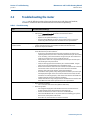
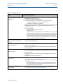
2.2
3-9000-767 Rev A
Troubleshooting the meter
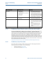
Table 2-1 and the following sections show errors that may occur with the meter hardware,
firmware or connections and recommended actions to resolve the problem(s).
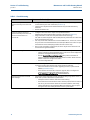
Table 2-1 Troubleshooting
Error
Recommended action(s)
Acquisition Module Error
•
•
Check interconnect cable between Acquisition Module and the CPU Module.
Attempt the Program Download procedure to install the firmware.
— Cycle power to the meter.
— Replace the Acquisition Module (see Section 3.4.4).
— If the Acquisition Module cannot be reprogrammed, collect a complete
Archive log and contact your local area Daniel service representative.
Acquisition Module is not compatible with firmware
•
Upgrade the firmware in the meter to the latest version using Daniel MeterLink.
Contact your Daniel service representative to obtain the latest firmware.
Replace the Acquisition Module.
•
Chord failure
•
Chord is hard failed (Chord A or Chord B) and meter is unable to obtain measurement data from this pair of transducers.
— If Chord A (or Chord B) is failed and no other transducers are failed or are
reporting status alerts, the issue is most likely isolated to this pair of transducers or its cabling. Check the transducer wiring for this pair of transducers to
make sure connections are secure and wired correctly.
— Verify that the meter run is not partially full where the top transducer pair is
not submerged in the process fluid.
— Verify the average gain of this transducer pair is not above 90dB. The gain
value can be read in Daniel MeterLink on the Monitor page.
— Remove the transducer cable from the transducer and measure the resistance
with an Ohm meter across the two pins on the back of the transducer
housing. If the value is over 2 ohms, replace the transducers.
— If transducer cabling allows, swap cabling of failed transducer pair with a pair
with equal path lengths. If the alarm remains active for this chord, then the
transducers are working properly. If this alarm clears but the chord that was
swapped now fails, the issue is with the transducer.
— Collect a Maintenance Log, Configuration file and Waveform stream file with
Daniel MeterLink and contact your Daniel service representative.
CPU Module LINK LED
•
When connecting directly:
— Use a cross-over cable connection (P/N 2-3-3400-079)
When Using a Hub:
— Use straight-through patch cable between the meter and the hub and a
straight-through patch cable between the hub and the PC
— Do not connect either the meter or PC to the hub UPLINK port
— Check the CPU Module LED 1 is on (either solid red or flashing green). If the
LED is not on, check power to the meter.
— If the LED is on, check the Ethernet cable connections
•
12
Troubleshooting the meter
Maintenance and Troubleshooting Manual
Section 2: Troubleshooting
3-9000-767 Rev A
June 2011
Table 2-1 Troubleshooting
Error
Recommended action(s)
CPU Module LINK LED is on but I
can't communicate with the meter
using Ethernet
•
•
•
•
•
If you are connecting for the first time, refer to Section 3.5 for instructions on initial
communication (via Ethernet) setup
Enable the DHCP switch on the CPU Module
Verify that the PC has received an IP address from the meter as follows:
— bring up DOS prompt window (Start->Run->(type)cmd)
— in the DOS prompt window, type ipconfig
If you get the following: IP 192.168.135.35 (note: the last .35 can be up to .44) with
a Subnet Mask of 255.255.255.0 and Default Gateway you should be able to
connect to the meter
If you get the following:
— Ethernet adapter Local Area Connection 1:
— IP Address: 0.0.0.0
— the PC has not yet received an IP address from the DHCP server wait (up to 30
seconds) to receive an IP address before attempting to connect to the meter
— after 30 seconds the PC has not received an IP address from the DHCP server
or the IP address shown above (from ipconfig) is different from the range of
192.168.135.35 through 192.168.135.44, verify that the PC is configured to
receive its IP address automatically (via DHCP)
Communication line connected to
the flow computer but no signal is
received
•
•
Check for loose connections at the flow meter and the flow computer.
Check the CPU Module settings.
Communicating with meter but all
chords display failures
•
•
•
Verify that the resistance of transducers is within specification (2 M.
Check the Acquisition Board.
Check the interconnect cables between the Base Enclosure and the Transmitter
Electronics Enclosure.
Cannot communicate with Daniel
•
•
Ensure that the meter is properly powered.
Ensure that the computer cable is properly connected and check your interface pins
(RS-485 or RS-232).
Verify that the communication parameters of the Daniel MeterLink program are
correctly set.
Check RS-485 or RS-232 communication.
MeterLink program
•
•
Cannot communicate with 475 Field •
Communicator
Cannot communicate with AMS
Device Manager
Troubleshooting the meter
•
Refer to the Emerson 475 Field Communication User’s Manual, Rev D. This manual
may be downloaded from the following location:
http://www2.emersonprocess.com/en-US/brands/Field-Communicator/Pages/
Documentation.aspx
— Note: The 375 Field Communicator is no longer available for purchase since
the release of the 475 Field Communicator. Customer support for the 375
Field Communicator remains available.
Refer to the AMS help documentation and support at the following web site:
http://www.emersonprocess.com/ams/suppinde.htm
13
Section 2: Troubleshooting
Maintenance and Troubleshooting Manual
June 2011
3-9000-767 Rev A
Table 2-1 Troubleshooting
Error
Recommended action(s)
Connect to multiple meters via
•
Ethernet when they are on the same
LAN
•
•
Connect to multiple meters via
•
Ethernet when they are on the same
hub but not connected to an
•
intranet LAN
•
•
Configure each meter with a unique user-specified IP address (following the initial
communication quick start instructions (Section 3.5).
Contact your IT department for valid IP addresses for your LAN and Gateway
addresses.
Disable the DHCP server.
Configure each meter with a unique user-specified IP address
(following the initial communication quick start instructions (Section 3.5).
Assign each meter on the hub a unique IP address within the range
192.168.135.150 through 192.168.135.254 (Gateway address for each meter may
be left unconfigured as 0.0.0.0).
A PC may receive its IP address from an external DHCP server; in this case, one and
only one meter must have its DHCP server enabled (the DHCP server will serve up to
10 IP addresses to PCs attempting to talk to all meters on the hub).
Once a meter's IP address is configured, the meter may be connected to the hub
and accessed using that IP address.
Configuration changed
•
One or more parameters have been modified in the meter's configuration
— Collect an Audit log using Daniel MeterLink in order to see what configuration
parameters changed and when they changed.
— Run the Tools>Edit CompareConfiguration utility and click the Write All
button or select the checkbox in the value column and click Write Checked
button to write the changes to the meter.
— Save the configuration file.
Configuration lost
•
The meter configuration has reset to default values and the meter is not configured
correctly to measure flow and the meter has performed a Cold Start.
— Unless the Cold Start occurred after upgrading firmware, replace the CPU
Module (see Section 3.4.1).
— If the cold start occurred after a firmware upgrade, fully re-configure the
meter from a previously saved configuration using the
Tools>Edit/Compare Configuration in Daniel MeterLink.
Electronics Temperature is Out Of
Nominal Range
•
Temperature of the electronics is out of nominal operating range (below -40 °C or
above 100 °C) which could lead to a system failure.
— Attempt to warm or cool the meter electronics housing.
— If the electronics is mounted to the meter and the process fluid in the meter is
over 65 °C, you must remote mount the electronics off of the meter body.
— Collect a Maintenance log using Daniel MeterLink while the meter is experiencing the issue and contact your Daniel service representative.
14
Troubleshooting the meter
Maintenance and Troubleshooting Manual
3-9000-767 Rev A
Section 2: Troubleshooting
June 2011
Table 2-1 Troubleshooting
Error
Recommended action(s)
Flow pressure is outside the alarm
limits
•
•
Flow temperature is outside the
alarm limits
•
•
Troubleshooting the meter
Startup Issues:
— Verify that there is voltage to the pressure sensor from either the meter's
power supply board or from an external power supply.
— If using an analog pressure device, verify that the pressure sensor is properly
wired to the connector.
— Verify the input is properly configured for your pressure input.
— If using a flow computer to write pressure to the meter, verify that it is
properly writing to fixed flow pressure in the proper units.
Run Time Issues:
— If using an analog pressure device and input reading is 0, check if IsAI2Avail is
equal to 1 in the Meter Information dialog in Daniel MeterLink. If it is not 1,
either the I/O Board has been removed or is damaged. Reinstall or replace the
CPU Module if this value is 0.
— If using an analog pressure device, verify that the pressure sensor is working
properly.
— If using an analog pressure device, recheck wiring and switch settings.
— If a flow computer is writing values to the fixed flow pressure, verify that the
flow computer is still writing valid values without Modbus write errors.
— Reverify the pressure input settings are correct.
Startup Issues:
— Verify that there is voltage to the temperature sensor from either the meter's
power supply board or from an external power supply.
— If using an analog temperature device, verify that the temperature sensor is
properly wired to the connector.
— Verify the input is properly configured for your temperature input.
— If using a flow computer to write temperature to the meter, verify that it is
properly writing to fixed flow temperature in the proper units.
Run Time Issues:
— If using an analog temperature device and input reading is 0, check if
IsAI2Avail is equal to 1 in the Meter Information dialog in Daniel MeterLink. If
it is not 1, either the I/O Board has been removed or is damaged. Reinstall or
replace the CPU Module if this value is 0.
— If using an analog temperature device, verify that the pressure sensor is
working properly.
— If using an analog temperature device, recheck wiring and switch settings.
— If a flow computer is writing values to the fixed flow temperature, verify that
the flow computer is still writing valid values without Modbus write errors.
— Reverify the temperature input settings are correct.
15
Section 2: Troubleshooting
Maintenance and Troubleshooting Manual
June 2011
3-9000-767 Rev A
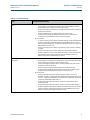
Table 2-1 Troubleshooting
Error
Recommended action(s)
Program download failed during
firmware upgrade
•
If the meter power fails during a firmware upgrade process, perform a backup
upgrade in an attempt to connect to the meter and download the program again.
— In Daniel MeterLink go to the File pull-down menu and select Program
Settings.
— Enable the Allow FTP-only connection
— For Serial Port Connections: Connect to Port A. You may need to adjust your
Meter Directory settings for the connection so that they match the port
default settings. Port A will default to 19200 baud with a Modbus address of
32.
— For Ethernet Connections: If you are connecting to the meter over an Ethernet
port, you should be able to connect with the same IP address as normal. If this
is unsuccessful, the meter may have defaulted to 192.168.135.100 with a
subnet of 255.255.255.0. Make sure your PC has a compatible address and
attempt a connection using this IP address.
— Make sure your cabling and your Meter Directory record are setup attempt to
connect to the meter.
— You will receive a message “Error 10001 opening database connection to...”.
Click OK and you will be prompted to “Attempt FTP-only connection ….”. Click
Yes and if successful, the Daniel MeterLink caption displays “…Connected to
<meter name>…”. Go to the Tools pull down menu and select Program
Download to attempt the firmware upgrade again.
— If the firmware upgrade is successful, the meter should start working as
normally as the meter’s configuration is not normally lost.
— If the configuration is lost, use Daniel MeterLink Edit/Compare Configuration
to write the saved configuration back to the meter. The saved configuration
files a typically stored in C:\Ultrasonic Data folder.
— Restart the meter to install the firmware. Daniel MeterLink prompts you with a
message that it must disconnect from the meter. Once the firmware upgrade
is complete you will be able to reconnect to the meter with Daniel MeterLink.
— When the meter restarts, it takes about two minutes before you will be able to
reconnect depending on the firmware upgrade being performed. If the
database does need to be reinitialized, it could take up to five minutes.
— After an upgrade, it is recommended to reconnect to the meter and repeat
the Program Download process.
— If all the program components are successfully updated, they will show to be
the same date and version as the Currently Installed Versions and the
Download button will be disabled.
— If one or more components are still not updated, click Download to continue
the upgrade process.
No power to the unit
•
Check that the correct voltage level is in the range of 11-36 VDC at the meter (refer
to the System Wiring Diagram in Appendix B).
Check the main power source for blown fuse or tripped circuit breaker (see
Section 3.4.2). Reference your “as built” installation drawings for your location.
•
16
Troubleshooting the meter
Maintenance and Troubleshooting Manual
3-9000-767 Rev A
Section 2: Troubleshooting
June 2011
Table 2-1 Troubleshooting
Error
Recommended action(s)
One or more of the chords is not
indicating a reading (reporting
zeros)
•
•
•
•
•
•
Check for loose connections at the cable connectors.
Check the resistance of the transducers (should be approximately 2 M).
Problem also may be caused by a bad Acquisition Board or interconnect cable.
Check system status in the Daniel MeterLink program for any flagged errors.
Check the CPU Module.
If Chord A is not indicating, change the transducer cables from Chord B to chord A.
If Chord B then fails, the transducers are bad on Chord A.
Power Failure
•
Meter has had power removed for a period of time or the meter restarted itself such
as after a firmware upgrade. The Audit log in the meter indicates the power fail
time.
— If this was an unexpected restart of the meter, verify the integrity of the power
to the meter and make sure that the voltage level is the in the range of 11-36
VDC at the meter.
— If this was a known power fail or restart of the meter, just acknowledge this
alarm.
Sound velocity is outside defined
limits
•
The meter's measured average sound velocity is outside the defined limits.
— Verify that all chords are measuring the same Speed of Sound within about
0.15%. Look for alarms that indicate transducer problems and resolve any of
these issues. This could include failing transducers, debris buildup on transducers, or incorrectly entered path lengths in the configuration.
— If the chords agree, adjust the SSMin or SSMax using the Field Setup Wizard in
Daniel MeterLink so the meter's average speed of sound falls within these
limits (consult with a Daniel service representative before before changing
these parameters).
— Collect a Maintenance log using Daniel MeterLink and contact your Daniel
service representative.
Waveform contains an excessive
amount of noise
•
Use the Daniel MeterLink Meter>Signal Analyzer to increase the StackSize until
noise level decreases (settings can be 1 (none) 2, 4, 8, or 16). If increasing the
StackSize is not successful, try turning on the filter or consult with Daniel Customer
Service if you are unsure of how stacking a signal can affect the meter's operation.
Troubleshooting the meter
17
Section 2: Troubleshooting
June 2011
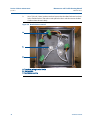
2.2.1
Maintenance and Troubleshooting Manual
3-9000-767 Rev A
Meter maintenance
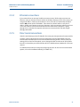
Run Daniel MeterLink and open the Meter Monitor (Summary) to view the current health status
of your meter.
The Monitor (Summary) includes the direction of flow measurement, velocity rate, units of
measurement, uncorrected or corrected flow (if applicable for your meter) and a bar graph for a
visual comparison between the velocities for each chord.
Figure 2-4 Meter Monitor (Summary) view
Refer to Table 2-1 for error resolutions and Table 2-2 for meter maintenance hardware diagnostics.
18
Meter maintenance
Maintenance and Troubleshooting Manual
Section 2: Troubleshooting
3-9000-767 Rev A
June 2011
Table 2-2 Maintenance
Daniel MeterLink utility
Diagnostics
Action(s)
Meter Monitor (Summary) view
•
•
Check Status for active alarms
•
Meter Monitor (Detailed) view
•
Flow Profile
•
•
•
•
•
•
•
Meter Monitor (Summary) view
Meter Flow Properties Table
•
Flow velocity
•
•
Meter maintenance
Meter Status LED is green if there are
no active alarms. This indicates the
meter is measuring flow and
operating within the calibrated
parameters.
Meter Status LED is red. This indicates
an active alarm. Resolve and acknowledge active alarms as displayed on
the Status Summary page. Click the
Help button
beside the alarm
description to display information
about the alarm and recommended
actions to resolve the issue.
Flow profile velocity for Chords A and
B shown on the Bar graph should be
of equal lengths and at 3 ft/s should
be 1.0 (range of 0.95 to 1.05 indicates
a good flow profile velocity).
If the velocity ratiois greater than a
10% differential between chords, a
degradation in the symmetry is indicated.
Check for a chord failure and resolve
this and clear the alarm.
If installed, check the flow
conditioner for blockage.
Compare gains and Signal to Noise
(SNR) ratios decibel values with the
meter calibration values in the Maintenance log Inspection report.
The meter may not be in measurement mode or there are too few
operating chords.
Check chord average signal amplitudes with the meter baseline values
in the Maintenance log Inspection
report.
Check the flow direction. If reverse
flow is detected, check for valve leaks.
If the meter run typically has reverse
flow when flow is stopped, use the
Field Setup Wizard >General Page and
reconfigure the ReverseFlowVolLmt
to allow a higher volume.
19
Section 2: Troubleshooting
Maintenance and Troubleshooting Manual
June 2011
3-9000-767 Rev A
Table 2-2 Maintenance
Daniel MeterLink utility
Diagnostics
Action(s)
Meter Monitor (Detailed) view
Monitor Chart Selection list
•
•
Speed of Sound
•
•
•
•
Compare Speed of Sound deviation
from measured SOS relative to the
average SOS.
Check the chord’s SOS.
Check and correct geometry configuration (pipe diameter, distance
between the transducers (LA), and
delay time).
If present, resolve transducer issues
(failed transducer, cabling or debris
buildup on the transducer face, or
path length configured incorrectly).
Adjust SSMin or SSMax (consult a
Daniel Service representative before
making these adjustments).
Meter Monitor (Detailed) view
Meter Data List
•
Electronics temperature out of
range
•
Temperature of the electronics is out
of nominal operating range
below -40 °C or above 100 °C (-40 °F
or above 212 °F).
— Heat or cool the meter electronics housing. If operating
temperature exceeds 65oC,
remote mount the Transmitter
Electronics Enclosure.
Meter Monitor (Detailed) view
Meter Data List
•
Electronics voltage out of range
•
CPU board system voltages are valid if
1.0V, 1.2V, 2.5V, 3.3V or the Acquisition Module valid voltages are 1.2V,
2.5V or 3.3V.
Replace the CPU Module if one or
more of the System Voltages is out of
range.
Replace the Acquisition Module if one
or more of the voltages is out of
range.
•
•
20
Meter maintenance
Maintenance and Troubleshooting Manual
Section 2: Troubleshooting
3-9000-767 Rev A
June 2011
Table 2-2 Maintenance
Daniel MeterLink utility
Diagnostics
Action(s)
MeterLink Tools Menu
•
•
•
Frequency output
•
Run the Frequency Outputs test.
If the output reads zero, you may
require a pull up resistor 1.2kOHM,
0.5W.
Check frequency output from
minimum to maximum values.
MeterLink Tools Menu
•
Analog outputs
•
Run Analog Outputs test and verify
outputs are within 4mA -20mA range
— 0% = 4mA
— 25% = 8mA
— 50% = 12mA
— 75% = 16mA
— 100% = 20 mA
MeterLink Tools Menu
•
Digital outputs
•
•
Run Digital Outputs test.
Digital Output Content is in relation
to frequency validity and flow
direction configuration and polarity.
Meter maintenance
21
Section 2: Troubleshooting
Maintenance and Troubleshooting Manual
June 2011
3-9000-767 Rev A
Meter Hardware
Diagnostics
Action(s)
Meter Electronics
•
•
Acquisition Module communications error
•
•
MeterLink Logs/
Reports Menu
•
Meter performed a Warm start or a warm
start is required
•
•
22
If the CPU Module LED 5 is not flashing green,
check interconnect cable between Acquisition
Module and the CPU Module.
Check firmware revision and upgrade if
necessary using Daniel MeterLink Tools>Program Download.
If the CPU Board LED 5 is not flashing green,
replace Acquisition Module (see
Section 3.4.4).
Meter performed a Warm Start:
— Collect an Archive event log (Audit log)
using Daniel MeterLink to view configuration parameters changes and when
they changed.
Warm start required:
— When you make changes to the transducer characteristics, sample rates, the
device number, or a Modbus map file.
Meter maintenance
Maintenance and Troubleshooting Manual
Section 2: Troubleshooting
3-9000-767 Rev A
Meter Hardware
(Continued)
June 2011
Diagnostics
MeterLink Tools>Edit/ •
Compare Configuration Menu
Meter performed a Cold Start
Action(s)
•
•
•
MeterLink Logs/
Reports Menu
•
Power failure
•
•
•
Daniel MeterLink
Meter Monitor
(Summary) view
•
Chord Failure
•
•
•
•
•
Meter maintenance
The meter configuration has reset to default
values and the meter is not configured
correctly to measure flow.
Unless the cold start occurred after upgrading
firmware, you may need to replace the CPU
Module.
If the Cold Start occurred after a firmware
upgrade, you must reconfigure the meter
from a previously saved configuration file
using the Edit>Compare Configuration screen.
Then clear the latched alarm on the Status
Summary page.
If this was a known power fail or restart of the
meter just acknowledge this alarm on the
Status Summary page.
If this was an unexpected restart of the meter,
verify the integrity of the power to the meter
and make sure that the voltage level is in the
range of 11-36 VDC at the meter.
Collect an Archive event log (Audit log) using
Daniel MeterLink.
The meter is unable to obtain measurement
data from a pair of transducers.
The cause may be isolated to one pair of transducers or its cabling. Check the transducer
wiring for this pair of transducers to make sure
connections are secure and wired correctly.
Verify that the meter run is not partially full
where this top transducer pair is not
submerged in the process fluid.
Verify the average gain of this transducer pair
is not above 90dB. Read the value from the
Daniel MeterLink Monitor Page or using AMS
under Service Tools>Path performance.
Remove the transducer and clean the transducer face. Reapply coupling fluid to the
transducer face and reinstall (see
Section 3.2.1 Transducer removal procedure).
23
Section 2: Troubleshooting
Maintenance and Troubleshooting Manual
June 2011
3-9000-767 Rev A
Meter Components
Visual Inspection
Action(s)
Security seals
•
•
•
•
•
Endcap seals
Endcaps latches
Transmitter Electronics Enclosure
Base Enclosure
Shroud seals
•
Only authorized personnel may
remove security seals. Follow your
standard operating procedure to
report seals that have been tampered
with or removed and replace the seals
per instructions in Section 3.6.8 in the
Installation Manual (3-9000-765).
External ground wiring
•
Transmitter Electronics Enclosure
ground lug
•
Inspect ground lug wiring and make
sure the wiring is tightly secured.
Conduit seals
•
Transmitter Electronics Enclosure
•
Inspect the conduit sealant and follow
your standard operating procedure to
report tampering with the conduit
sealant.
Your operating procedures may
require a certified electrician and
company witness to reseal the
conduit.
•
•
Flanges
2.2.2
Inspect for leaks
•
Perform leak tests on flanges
Unable to connect direct serial or external serial modem
If you are using Windows® XP, Windows® Vista or Windows® 7 make sure that you do not have
more than one modem driver installed to the same COM port. Typically this will only be
necessary if you use one COM port to talk direct (serial communications) and use the same COM
port to connect to an external modem. This is an apparent limitation in Microsoft’s® Dial-up
Networking. If more than one modem driver is installed for a particular COM port, Dial-up
Networking will always use the last driver installed regardless of what is selected. The only work
around is to only install one modem driver per COM port on the PC at a time. Refer to the Daniel
MeterLink Quick Start Manual (P/N 3-9000-763) for phone and modem details. The manual may
also be downloaded from the Daniel website.
http://www2.emersonprocess.com/en-US/brands/daniel/Flow/ultrasonics/Pages/Ultrasonic.aspx
2.2.3
Unable to connect to meter
If you receive the error message “Unable to connect to meter” when trying to connect to a
Daniel Liquid Ultrasonic Flow Meter, refer to the following:
24
•
Ethernet Connections (Section 2.2.4)
•
Direct Serial Connections (Section 2.2.5)
Unable to connect direct serial or external serial modem
Maintenance and Troubleshooting Manual
3-9000-767 Rev A
2.2.4
Section 2: Troubleshooting
June 2011
Ethernet connections
If you received the error message "Unable to connect to meter" while trying to connect over
Ethernet, verify you have the correct IP address in the Meter Directory record. If the meter is to
assign the IP address, make sure the IP address is set to 192.168.135.100 and that the DHCP
switch is ON position on the CPU Module. If the meter has a fixed IP address, verify the IP
address, Subnet, and Gateway are correct in the meter. Verify your wiring to make sure you have
a cross-over cable for a direct connection between the meter and the computer. If going
through a hub, verify that the computer and meter are connected to the hub with straightthrough patch cables.
2.2.5
Direct serial connections
Verify the switch settings on the CPU Module. Also verify your wiring between the meter and the
computer running Daniel MeterLink using the Field Wiring drawing DMC-004946. Verify the
Comms Address and Baud rate are correct in the Meter Directory record. If unsure of the port
settings for Port A on the CPU module, you can change the PORT A switch on the CPU module
from OFF to ON and the port will be forced to RS-232, 19200 baud rate, Modbus ID =32 for two
minutes.
For additional information on wiring and configuring the meter for the various communication
options, refer to the Installation Manual (P/N 3-9000-765).
Ethernet connections
25
Section 2: Troubleshooting
Maintenance and Troubleshooting Manual
June 2011
3-9000-767 Rev A
2.3
Troubleshoot Maintenance log files and trend files
2.3.1
Files do not appear in workbook
Maintenance Log files and Trend files that exist on the PC do not appear in the Microsoft®
Excel® workbooks tree under Trend Maintenance Logs.
This is most likely caused by the fact that the desired file or files are already open in Microsoft®
Excel®. Open files can not be verified as Maintenance Log files or Trend Files by
Daniel MeterLink and are left out of the list. Simply close the files in Microsoft® Excel® and then
close and reopen the Trend Maintenance Logs dialog box to include them in the list.
2.3.2
Microsoft® Excel® Log/Export options are not available
In order for the Excel® log/export options to be available, Excel® 2000 or later must be installed
on the machine and at least one printer must be installed under the Windows® operating
system.
If Excel® 2000 or later is installed and you have printers installed but the Excel® option is still
unavailable, it may be because Excel® cannot access the printer driver information of the
Windows® default printer. If the Windows® default printer is a network printer and you are not
currently connected to the network, then Excel® will most likely not be able to access the
printer driver information and Daniel MeterLink cannot use Excel® to generate reports or logs.
One solution is to install a local printer on your machine tied to LPT1. The local printer driver you
installed can be for any printer and the printer does not actually have to exist or be connected to
the PC. If you install a local printer, you can configure Daniel MeterLink to temporarily change
your Windows® default printer over to this local printer while running Daniel MeterLink. Do this
by selecting this local printer for the Override system default printer selection in the Program
Settings dialog. Daniel MeterLink will automatically change the Windows® default printer to
the selected override printer when it starts and will set the Windows® default printer back to its
original printer when it closes.
26
Troubleshoot Maintenance log files and trend files
Maintenance and Troubleshooting Manual
Section 2: Troubleshooting
3-9000-767 Rev A
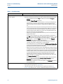
2.3.3
June 2011
Maintenance Logs or Trend files are not created
When using Excel® XP or later, some of the worksheets in the Maintenance Logs or Trend files
are not created.
If the Inspection sheet of the Maintenance Log file or the Charts sheet of a Trend files is not
generated, it is probably because Excel® is not configured to allow Daniel MeterLink to run the
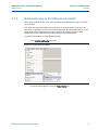
Visual Basic® script that generates the page. Excel® can be configured to allow Daniel
MeterLink to run the Visual Basic® script by following the instructions below.
To enable Excel® 2000 to work with Daniel MeterLink,
1.
Select Tools>Macros>Security menu path.
Figure 2-5 Excel® 2000 Tools Menu
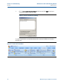
2.
The Security dialog appears. Select the Trusted Sources tab.
Maintenance Logs or Trend files are not created
27
Section 2: Troubleshooting
Maintenance and Troubleshooting Manual
June 2011
3-9000-767 Rev A
3.
Click the Trust access to Visual Basic Project radio button and click OKAY to apply your
selections.
Figure 2-6 Excel® Trusted Access Setting
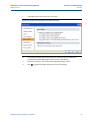
To enable Excel® 2007 to work with Daniel MeterLink customize the Ribbon to include the
Developer tab,
Figure 2-7 Excel® 2007 Tools Menu
28
Maintenance Logs or Trend files are not created
Maintenance and Troubleshooting Manual
Section 2: Troubleshooting
3-9000-767 Rev A
June 2011
1.
Select Macro Security to access the Trust Center.
Figure 2-8 Excel® 2007 Developer tab - Macro Security
2.
Select Macro Settings from the left panel, then click the Enable all macros (not
recommended; potentially dangerous code can run) radio button.
3.
Place a check mark in “Trust access to the VBA project object model”.
4.
Click OK to apply the changes and close the Trust Center dialog.
Maintenance Logs or Trend files are not created
29
Section 2: Troubleshooting
Maintenance and Troubleshooting Manual
June 2011
2.3.4
3-9000-767 Rev A
Windows® XP with Security Update
The Security Update for Windows® XP (823980) has a problem that causes the Show only
maintenance log and trend workbooks check box in Daniel MeterLink to be ineffective.
See http://www.microsoft.com/downloads/en/details.aspx?FamilyID=2354406c-c5b6-44ac9532-3de40f69c074
Additionally, it may take longer to validate a workbook when you attempt to add it to the
Workbooks to trend list. This is a known Issue documented in the Microsoft® Knowledge Base
Article 824136 Windows® Explorer Quits Unexpectedly or You Receive an Error Message When
You Right-Click a File. For Windows® XP, simply install Service Pack 2 for Windows® XP to
resolve the issue. It is not necessary to take action on this issue to use the Trend Maintenance
Logs dialog, but you should be aware of possible slow downs if the issue is unresolved.
30
Windows® XP with Security Update
Maintenance and Troubleshooting Manual
Section 3: Meter maintenance
3-9000-767 Rev A
June 2011
Section 3: Meter maintenance
31+
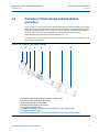
3.1
Maintenance
This section includes discussion of the maintenance of Daniel 3812 Liquid Ultrasonic Flow
Meters.
SURFACE TEMPERATURE HAZARD
Meter body and piping may be extremely hot or cold
Wear personal protective equipment when coming in contact with the meter. Failure to do
so may result in injury.
TRANSPORTATION HAZARD
When moving the meter, do not insert the forks of a forklift into the bore.
Inserting the forks may cause the meter to become unstable, resulting in injury or damage to
the bore and sealing face.
TRIPPING HAZARD
Clear all obstacles or obstruct.ions from the work area when transporting, installing or
removing the meter.
Failure to clear the work area may cause injury to personnel.
Prior to lifting the unit, refer to the Daniel 3812 Liquid Ultrasonic Flow Meter nameplate or
outline dimensional (general arrangement) drawing for the assembled weight.
Maintenance
31
Section 3: Meter maintenance
Maintenance and Troubleshooting Manual
June 2011
3-9000-767 Rev A
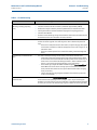
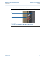
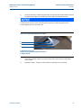
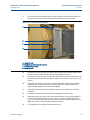
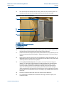
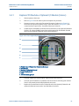
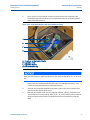
CRUSHING HAZARD
Do not remove flange stabilizers
Attempting to do so may allow the meter to roll, resulting in serious injury or equipment damage.
Figure 3-2 Flange stabilizers
A.
A. Flange stabilizers
32
Maintenance
Maintenance and Troubleshooting Manual
Section 3: Meter maintenance
3-9000-767 Rev A
June 2011
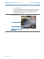
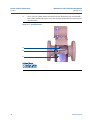
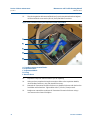
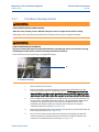
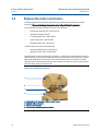
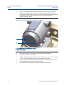
FLUID CONTENTS MAY BE UNDER PRESSURE
When the meter is under pressure, DO NOT attempt to remove or adjust the transducer housing.
Attempting to do so may release pressurized fluid, resulting in serious injury or equipment damage.
FLUID CONTENTS MAY BE HAZARDOUS
The meter must be fully depressurized and drained before attempting to remove the transducer housing.
If fluid begins to leak from the transducer housing, immediately reinstall it.
Failure to do so may cause serious injury or equipment damage.
A.
A. Transducer housing
Maintenance
33
Section 3: Meter maintenance
Maintenance and Troubleshooting Manual
June 2011
3-9000-767 Rev A
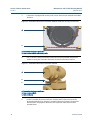
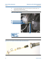
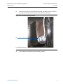
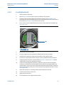
ESCAPING FLUIDS HAZARD
The purchaser of the meter is responsible for the selection of Daniel components/seals and materials
compatible with the chemical properties of the measurement fluid.
Failure to select suitable meter components/seals may cause escaping fluids, resulting in injury or equipment
damage
CRUSHING HAZARD
During meter installation or removal, always place the unit on a stable platform or surface that supports
its assembled weight.
Failure to do so could allow the meter to roll, resulting in serious injury or equipment damage.
34
Maintenance
Maintenance and Troubleshooting Manual
Section 3: Meter maintenance
3-9000-767 Rev A
3.2
June 2011
Transducer field removal and installation
procedure
The LT-10 and LT-11 transducers have a spring loaded assembly with the piezoelectric element
at one end and the electrical connection at the other end. Meters are supplied with transducers
which are extractable while the line is pressurized. The transducer assembly shown below is a
one-piece capsule that can be easily installed or removed from the meter without
depressurizing the unit using the tool list provided in Figure 3-4.
LT-10 transducers are designed for 4 inch to 10 inch meter sizes and LT-11 are designed for 12
inch and larger meters sizes.
Figure 3-3 LT-10 and LT-11 transducer assembly
A.
B.
C.
D.
E.
F.
G.
H.
A. Transducer cable (P/N 1-504-90-129) (max. length 15 ft.)
B. Feed-thru cable seal (P/N 1-504-90-178)
C. Retaining ring (P/N 1-504-08-009)
D. Shoulder washer (P/N 1-504-90-181)
E. Spring (P/N 1-504-90-046)
F. Transducer capsule (LT-10 P/N 1-360-01-624) or (LT-11 P/N 1-360-01-823)
G. O-ring (part numbers vary)
H. Transducer housing (P/N 1-360-01-632 for 316L SS or P/N 1-360-01-633 Inconel)
Transducer field removal and installation procedure
35
Section 3: Meter maintenance
Maintenance and Troubleshooting Manual
June 2011
3.2.1
3-9000-767 Rev A
Transducer removal
CUTTING HAZARD
Sharp edges may be present on the meter.
Wear appropriate personal protective equipment when working on the meter. Failure to do so
may cause serious injury.
Tools required:
Figure 3-4 Tools required
A.
B.
C.
D.
E.
F.
G.
H.
A. Crescent wrench or channel lock pliers for cable glands and electrical conduit
B. 7/16 inch wrench (12 mm)
C. 3/8 inch drive ratchet wrench (10mm)
D. 3/8 inch drive (10mm) - at least 3.5 inch extension (89mm) with 7/16 (12mm) socket wrench
E. 1/4 inch (7mm) flat-blade screw driver
F. 1/8 inch (3mm) flat-blade screw driver (3mm)
G. Allen wrench - size 3mm (Daniel P/N 2-4-9200-501)
H. Retaining ring pliers (Daniel P/N 1-504-90-043)
36
Transducer removal
Maintenance and Troubleshooting Manual
3-9000-767 Rev A
Section 3: Meter maintenance
June 2011
1.
Remove power to the meter.
2.
If the installation has rigid conduit, use a medium size crescent wrench and loosen the
hex nuts on the Transmitter Electronics Enclosure. This should allow enough slack to
remove the Transmitter Electronics Enclosure from the Base Enclosure. If the
installation uses flexible conduit, you may not need to disconnect it from the
Transmitter Electronics Enclosure.
Figure 3-5 Conduit removal
A.
B.
A. Transmitter electronics enclosure
B. Conduit bolts
Transducer removal
37
Section 3: Meter maintenance
Maintenance and Troubleshooting Manual
June 2011
3-9000-767 Rev A
3.
If the meter is equipped with security seals, remove the seals from the bolts on the Base
Enclosure.
Figure 3-6 Transmitter Electronics Enclosure and Base Enclosure security seal removal
A.
B.
A. Transmitter electronics enclosure
B. Base enclosure bolts and security seals
4.
Use a 7/16 inch (12mm) wrench and remove the four hex head bolts and split lock
washers securing the Transmitter Electronics Enclosure to the Base Enclosure.
Figure 3-7 Transmitter Electronics Enclosure removal
A.
B.
C.
A. Transmitter electronics enclosure
B. Base enclosure bolts
C. Base enclosure
5.
38
Lift the Transmitter Electronics Enclosure off of the Base Enclosure to expose the
Acquisition Module wiring. Prop the Transmitter Electronics Enclosure on top of the
Base Enclosure and prepare to disconnect the Acquisition cable and transducer
terminal blocks.
Transducer removal
Maintenance and Troubleshooting Manual
3-9000-767 Rev A
Section 3: Meter maintenance
June 2011
6.
Use a 1/8 inch (3mm) flat blade screw driver to remove the Acquisition cable terminal
block screws. Unplug the Acquisition cable terminal block.
7.
Use a 1/8 inch (3mm) flat blade screw driver and remove the transducer wire terminal
blocks screws. Disconnect the transducer wires from the terminal blocks so that the
cables can be removed from the meter.
Make sure the transducer cables are labeled for the chord configuration (A1, A2, B1 and
B2).
Figure 3-8 Acquisition Module cable and transducer wiring
A.
B.
C.
D.
A.
B.
C.
D.
8.
Transducer removal
Acquisition cable and terminal block
Transducer wiring and terminal blocks
Acquisition Module
Base Enclosure
Use a 1/4 inch (7mm) flat blade screw driver and remove the three Acquisition Module
flat head screws, split lock washers, and flat washers then remove the Acquisition
Module from the Base Enclosure.
39
Section 3: Meter maintenance
June 2011
Maintenance and Troubleshooting Manual
3-9000-767 Rev A
9.
Use a 7/16 inch (12mm) socket wrench and remove the three Base Enclosure hex head
bolts, shoulder washers, flat washers and split lock washers and then remove the Base
Enclosure from the meter body.
Figure 3-9 Base Enclosure removal
A.
B.
C.
A. Transducer wiring terminal blocks
B. Hex hex bolts
C. Base Enclosure o-ring
40
Transducer removal
Maintenance and Troubleshooting Manual
Section 3: Meter maintenance
3-9000-767 Rev A
June 2011
10.
Remove the security seals from the Lower Shroud on the meter body.
Figure 3-10 Shroud security seal removal
A.
B.
A. Lower Shroud
B. Lower Shroud cover, hex head nuts, lock washers and Shroud clamps
Transducer removal
41
Section 3: Meter maintenance
June 2011
Maintenance and Troubleshooting Manual
3-9000-767 Rev A
11.
Use a 7/16 inch (12mm) wrench and remove the four Shroud hex nuts, external tooth
lock washers and Shroud clamps. Then, slide the lower Shroud down to remove it from
the meter body.
Figure 3-11 Shroud removal
A.
B.
C.
A. Upper Shroud
B. Transducer housing
C. Lower Shroud cover
42
Transducer removal
Maintenance and Troubleshooting Manual
3-9000-767 Rev A
Section 3: Meter maintenance
June 2011
12.
Use Retaining Ring pliers (Daniel P/N 1-504-90-043 or Stanley Proto #J371 or #371L) to
pull the transducer cable Feed-thru foam seal from the transducer housing.
Figure 3-12 Transducer and cable disassembly
A.
B.
A. Feed-thru cable seal removal
B. Retaining ring pliers
13.
Slide the Feed-thru seal down the cable.
Figure 3-13 Feed-thru cable seal removal
A.
A. Feed-thru cable seal
Transducer removal
43
Section 3: Meter maintenance
Maintenance and Troubleshooting Manual
June 2011
3-9000-767 Rev A
14.
Use the Retaining Ring pliers and remove the retaining ring, shoulder washer, and
spring from the transducer housing.
15.
Pull the transducer capsule from the housing.
Figure 3-14 Transducer removal
A.
B.
C.
A. Feed-thru cable seal
B. Shoulder washer
C. Spring
D. Transducer capsule
D.
Figure 3-15 LT-10 Transducer and cable assembly removed from meter
44
Transducer removal
Maintenance and Troubleshooting Manual
3-9000-767 Rev A
Section 3: Meter maintenance
June 2011
16.
Pull the transducer cable from the meter (down through the foam Feed-thru cable seal
on top of the meter body, the base cover gasket, nylon flat washers (Figure 3-16), and
through the upper Shroud, Figure 3-17, of the meter. Repeat for each transducer you
are removing.
Figure 3-16 Upper Shroud cable seal
A.
B.
C.
A. Base Enclosure
B. Cable feed-thru seal
C. Base cover gasket and nylon flat washers
Figure 3-17 Cable removal from meter
A.
B.
C.
A. Transmitter Electronics Enclosure
B. Upper Shroud
C. Transducer cable
17.
Transducer removal
This completes the transducer removal procedure.
45
Section 3: Meter maintenance
Maintenance and Troubleshooting Manual
June 2011
3-9000-767 Rev A
3.2.2
Transducer installation
Figure 3-18 LT-10 or LT-11transducer assembly
A.
B.
C.
D.
E.
F.
G.
H.
A. Transducer cable (P/N 1-504-90-129) (max. length 15 ft.)
B. Feed-thru cable seal (P/N 1-504-90-178)
C. Retaining ring (P/N 1-504-08-009)
D. Shoulder washer (P/N 1-504-90-181)
E. Spring (P/N 1-504-90-046)
F. Transducer capsule (1-360-01-624) or (LT-11 P/N 1-360-01-823)
G. O-ring (part numbers vary)
H. Transducer housing (P/N 1-360-01-632 for 316L SS or P/N 1-360-01-633 Inconel)
CUTTING HAZARD
Sharp edges may be present on the meter.
Wear appropriate personal protective equipment when working on the meter. Failure to do so
may cause serious injury.
46
Transducer installation
Maintenance and Troubleshooting Manual
Section 3: Meter maintenance
3-9000-767 Rev A
June 2011
1.
Place one drop of Dow Corning 200 Silicon Oil (12,500 Centistokes)
(P/N 1-360-01-650) on the face of the transducer to be installed.
2.
Insert the transducer capsule into the transducer housing inside the meter body.
3.
Slide the spring, shoulder washer and retaining ring onto the transducer cable. Insert
these components into the transducer housing.
Figure 3-19 Transducer, cable and components assembly
A.
B.
C.
A. Feed-thru cable seal
B. Retaining ring
C. Shoulder washer
D. Spring
E. Transducer capsule
F. Transducer housing
4.
Transducer installation
D.
E.
F.
Insert the Feed-thru cable seal into the housing groove with the Retaining Ring pliers.
47
Section 3: Meter maintenance
June 2011
Maintenance and Troubleshooting Manual
3-9000-767 Rev A
5.
Feed the transducer cable underneath the top Shroud to the top of the meter body.
Figure 3-20 Transducer cable installation
A.
B.
A. Upper Shroud
B. Transducer cable
48
Transducer installation
Maintenance and Troubleshooting Manual
Section 3: Meter maintenance
3-9000-767 Rev A
June 2011
6.
Insert the transducer cable through the Base cover gasket and and flat washers into the
Feed-thru foam cable seal. Feed the transducer cable into the Base Enclosure.
Feed-thru foam seals tear easily. Carefully pull the transducer cable through the seal to
prevent ripping the Feed-thru cable seal.
Figure 3-21 Upper Shroud Feed-thru cables
A.
B.
C.
A. Cable Feed-thru seal
B. Base cover gasket and nylon flat washers
C. Upper shroud
Transducer installation
7.
Ensure the nylon flat washers are in place between the Base Enclosure and the Base
Cover Gasket.
8.
Repeat the Steps1- 5 above for each transducer assembly you are replacing.
49
Section 3: Meter maintenance
June 2011
Maintenance and Troubleshooting Manual
3-9000-767 Rev A
9.
Reattach the Base Enclosure to the meter body with the three shoulder washers, flat
washers, split lock washers and hex head bolts. Tighten the bolts with a 7/16 inch
(12mm) socket driver.
Figure 3-22 Base Enclosure installation
A.
B.
C.
A. Transducer wiring terminal blocks
B. Hex hex bolts
C. Base Enclosure o-ring
50
Transducer installation
Maintenance and Troubleshooting Manual
3-9000-767 Rev A
Section 3: Meter maintenance
June 2011
10.
Insert the Acquisition Module into the Base Enclosure and secure with the three split
lock washers and flat head screws (see Figure 3-24). Position the cables to prevent
pinching when the Acquisition Module is attached.
11.
Cut the new transducer cable(s) to the correct length (maximum 15 feet) with
allowance for the wiring terminations and connector placement. Strip back about 1.5
inches of the cable outer sheath and 1/4 inch of insulation from the wires. When
stripping the outer sheath of the transducer cable, do not cut into the insulation of the
individual wires.
The transducer cables have two wires and a bare drain wire that must be terminated on
the applicable connector on the Acquisition Module. The red wire connects to the +
(positive) pin, the black wire (yellow wire in Figure 3-23) connects to the - (negative) pin
and the bare drain wire connects to the S-pin (Shield). Reattach the transducer cables
to the terminal blocks with a 3mm flat blade screw driver and screw the terminal block
onto the Acquisition Module for the corresponding chord (A1, B1, A2, or B2). Make sure
the transducer wires have good contact with the terminal block and the terminal block
screws are tight.
Figure 3-23 Transducer terminal block wiring
Transducer installation
51
Section 3: Meter maintenance
Maintenance and Troubleshooting Manual
June 2011
3-9000-767 Rev A
12.
Plug the Acquisition cable terminal block into J3 on the Acquisition board and tighten
the terminal block screws with a 1/8 inch (3mm) flat blade screw driver.
Figure 3-24 Transducer wiring and Acquisition cable reassembled
A.
B.
C.
D.
D.
A. Transducer wiring terminal blocks
B. Acquisition cable
C. Acquisition Module
D. O-ring
E. Base Enclosure
52
13.
Repeat these steps for other transducers you are replacing.
14.
When you have completed wiring the transducer cables to the Acquisition Module,
check the Base Enclosure o-ring and reinstall if necessary.
15.
Reattach the Transmitter Electronics Enclosure to the Base Enclosure with the four hex
head bolts and lock washers. Tighten bolts with a 7/16 inch (12mm) wrench.
16.
Retighten or reattach the conduit to the Transmitter Electronics Enclosure using a
crescent wrench or channel lock pliers.
Transducer installation
Maintenance and Troubleshooting Manual
Section 3: Meter maintenance
3-9000-767 Rev A
June 2011
17.
Slide the lower Shroud beneath the meter body. Make sure the transducer cables are
moved out of the way and will not be pinched when the Shroud is reinstalled.
Figure 3-25 Lower Shroud installation
A.
B.
C.
D.
A. Upper Shroud
B. Hex head nut with tooth lock washer
C. Shroud clamp and tab
D. Lower Shroud
Transducer installation
18.
Lift the lower Shroud until the bolts align with the upper Shroud tab and notches and
the lower Shroud is flush with the top inside lip of the upper Shroud.
19.
Install the four Shroud clamps onto the lower Shroud bolts and secure with the four hex
head nuts and external tooth lock washers. Tighten the nuts with a 7/16 inch (12 mm)
wrench.
20.
Apply power to the meter and connect to Daniel MeterLink. Open the Meter Monitor
(Detailed) view and verity the meter is acquiring data, the transducers have good
signals and flow profiles for the chords are displayed.
21.
In Daniel MeterLink, run the Zero Calibration utility to re-zero the meter at no-flow
conditions.
22.
Close your connection to Daniel MeterLink and prepare to seal the meter.
23.
Attach the security wire seals on the Transmitter Enclosure end caps and through the
hex head bolts on the Base Enclosure (see Figure 3-6) and then seal the Shroud (see
Figure 3-10). Refer to the Daniel 3812 Liquid Ultrasonic Meter Installation Manual (P/N 39000-765, Section 3.6.8) for detailed sealing instructions.
24.
This completes the transducer installation procedure.
53
Section 3: Meter maintenance
June 2011
3.3
Maintenance and Troubleshooting Manual
3-9000-767 Rev A
Transducer housing removal and installation
procedure
Daniel 3812 Liquid Ultrasonic Flow Meters utilize transducer housing s that contain the
transducer capsules and act as the pressure barrier between the transducers and the fluid.
Under normal maintenance such as transducer replacement, the transducer housing s do not
need to be removed. If it is necessary to remove the transducer housings, the following steps
detail how to safely remove and reinstall them.
The meter has integrally mounted transducer cables that require you to disconnect the cables
from the terminal blocks inside the Base enclosure and remove the transducer capsule from the
housing. This includes removing the Transmitter Electronics Enclosure, the Acquisition Module,
the Base Enclosure and the Lower Shroud.
CUTTING HAZARD
Sharp edges may be present on the meter.
Wear appropriate personal protective equipment when working on the meter. Failure to do so
may cause serious injury.
54
Transducer housing removal and installation procedure
Maintenance and Troubleshooting Manual
Section 3: Meter maintenance
3-9000-767 Rev A
3.3.1
June 2011
Transducer housing removal
FLUID CONTENTS MAY BE UNDER PRESSURE
When the meter is under pressure, DO NOT attempt to remove or adjust the transducer housing.
Attempting to do so may release pressurized fluid, resulting in serious injury or equipment damage.
FLUID CONTENTS MAY BE HAZARDOUS
The meter must be fully depressurized and drained before attempting to remove the transducer housing.
If fluid begins to leak from the transducer housing, immediately reinstall it.
Failure to do so may cause serious injury or equipment damage.
A.
A. Transducer housing
1.
Remove power from the meter.
2.
Before removing the transducer housings, drain the meter of fluid and ensure the
pressure inside the meter is at atmospheric pressure. If fluid begins to leak from the
meter or leaking from the threads, immediately stop and reinstall the housing as the
meter has not been fully drained and/or pressure has not been relieved from the meter.
3.
If the installation has rigid conduit, use a medium size crescent wrench and loosen the
hex nuts on the Transmitter Electronics Enclosure. This should allow enough slack to
remove the Transmitter Electronics Enclosure from the Base Enclosure. If the
installation uses flexible conduit, you may not need to disconnect it from the
Transmitter Electronics Enclosure (see Figure 3-5).
4.
Remove the Transmitter Electronics Enclosure end cap security seals the seals from the
bolts on the Base Enclosure (see Figure 3-6).
5.
Use a 7/16 inch(12mm) wrench and remove the four hex head bolts and split lock
washers securing the Transmitter Electronics Enclosure to the Base Enclosure and
remove the Transmitter Electronics Enclosure (see Figure 3-7).
Transducer housing removal
55
Section 3: Meter maintenance
Maintenance and Troubleshooting Manual
June 2011
56
3-9000-767 Rev A
6.
Lift the Transmitter Electronics Enclosure off of the Base Enclosure to expose the
Acquisition Module wiring. Prop the Transmitter Electronics Enclosure on top of the
Base Enclosure and prepare to disconnect the Acquisition cable and transducer
terminal blocks and disconnect the transducer wiring terminal blocks (see Figure 3-8).
7.
Use a 1/8 inch (3mm) flat blade screw driver and disconnect the Acquisition cable
terminal block and unplug the Acquisition cable terminal block.
8.
Use a 3mm flat blade screw driver and disconnect the transducer wire terminal blocks
from the Acquisition Module. Disconnect the transducer wires from the terminal
blocks so that the cables can be removed from the meter.
9.
Use a 1/4 inch (7mm) flat blade screw driver and remove the three Acquisition Module
flat head screws, split lock washers, and flat washers then remove the Acquisition
Module from the Base Enclosure (see Figure 3-8).
10.
Use a 7/16 inch (12mm) socket wrench and remove the three Base Enclosure hex head
bolts, shoulder washers, flat washers and split lock washers and then remove the Base
Enclosure from the meter body (see Figure 3-9).
11.
Remove the Shroud security seals (see Figure 3-10).
12.
Use a 7/16 inch (12mm) wrench and remove the four Shroud hex nuts, external tooth
lock washers and Shroud clamps. Then, slide the lower Shroud down to remove it from
the meter body (see Figure 3-11).
13.
Use Retaining Ring pliers (Daniel P/N 1-504-90-043or Stanley Proto #J371 or #371L) to
pull the transducer cable Feed-thru foam seal from the transducer housing. Slide the
Feed-thru seal down the cable (see Figure 3-13).
14.
Use the Retaining Ring pliers and remove the retaining ring, shoulder washer, and
spring from the transducer housing (see Figure 3-13).
15.
Pull the transducer capsule from the housing.
16.
Pull the transducer cable from the meter (down through the foam Feed-thru cable seal
on top of the meter body, the base cover gasket, nylon flat washers (Figure 3-16), and
through the upper Shroud (Figure 3-17) of the meter).
17.
Repeat for each transducer capsule you are removing.
Transducer housing removal
Maintenance and Troubleshooting Manual
Section 3: Meter maintenance
3-9000-767 Rev A
June 2011
18.
Place a wrench on the hex of the transducer housing and slowly unscrew in a counterclockwise direction from the meter and remove it from the meter body.
Figure 3-26 Transducer housing removal
A.
A. Transducer housing
19.
Transducer housing removal
This completes the transducer housing removal procedure.
57
Section 3: Meter maintenance
Maintenance and Troubleshooting Manual
June 2011
3.3.2
3-9000-767 Rev A
Transducer housing Installation
CUTTING HAZARD
Sharp edges may be present on the meter.
Wear appropriate personal protective equipment when working on the meter. Failure to do so
may cause serious injury.
1.
Any time a transducer housing is removed from the meter the o-rings must be replaced
with new o-rings prior to reinstalling the housing in the meter. Apply a light coat of
Dow Corning 111 Silicone grease or equivalent to the o-rings.
Replace with new O-rings during transducer maintenance or after every ten years of service.
2.
Apply a light coat of Loctite® anti-seize nickel grade lubricant (20g stick-37230) on the
transducer housing threads.
3.
Ensure the transducer housing threads are properly aligned (avoid cross-threading the
housing) with the meter body, then use a wrench on the hex bolt of the housing and
slowly screw in a clockwise direction. Also, ensure the transducer housing is fully seated
against the meter body per the table below (Refer to SAE J514 specification, Table 2A).
Transducer
housing
Torque range
Ft-lb (N-m)
LT-10
40-43 (49-53)
LT-11
90-99 (122-134)
Transducer housing
Transducer
housing
58
Transducer housing Installation
Maintenance and Troubleshooting Manual
Section 3: Meter maintenance
3-9000-767 Rev A
June 2011
4.
Place one drop of Dow Corning 200 Silicon Oil (12,500 Centistokes)
(P/N 1-360-01-650) on the face of the transducer to be installed.
5.
Insert the transducer capsule into the transducer housing inside the meter body (see
Figure 3-19).
6.
Slide the spring, shoulder washer and retaining ring onto the transducer cable. Insert
these components into the transducer housing. Insert the Feed-thru cable seal into the
housing groove with the Retaining Ring pliers.
7.
Feed the transducer cable underneath the top Shroud to the top of the meter body.
Figure 3-27 Transducer installation
A.
B.
A. Upper Shroud
B. Transducer cable
Transducer housing Installation
59
Section 3: Meter maintenance
June 2011
Maintenance and Troubleshooting Manual
3-9000-767 Rev A
8.
Insert the transducer cable through the Base cover gasket and flat washers into the
Feed-thru foam cable seal. Feed the transducer cable into the Base Enclosure (see
Figure 3-16).
Feed-thru foam seals tear easily. Carefully pull the transducer cable through the seal to
prevent ripping the Feed-thru cable seal.
Figure 3-28 Upper Shroud Feed-thru cable seal
A.
B.
C.
A. Cable Feed-thru seal
B. Base cover gasket and nylon flat washers
C. Upper shroud
60
9.
Ensure the nylon flat washers are in place between the Base Enclosure and the Base
Cover Gasket.
10.
Repeat for each transducer housing and transducer assembly you replaced.
Transducer housing Installation
Maintenance and Troubleshooting Manual
3-9000-767 Rev A
Section 3: Meter maintenance
June 2011
11.
Reattach the Base Enclosure to the meter body with the three shoulder washers, flat
washers, split lock washers and hex head bolts. Tighten the bolts with a 7/16 inch
(12mm) socket driver (see Figure 3-22).
12.
Insert the Acquisition Module into the Base Enclosure and secure with the three split
lock washers and flat head screws (see Figure 3-24). Position the cables to prevent
pinching when the Acquisition Module is attached.
13.
Cut the new transducer cable(s) to the correct length (maximum 15 feet) with
allowance for the wiring terminations and connector placement. Strip back about 1.5
inches of the cable outer sheath and 1/4 inch of insulation from the wires. When
stripping the outer sheath of the transducer cable, do not cut into the insulation of the
individual wires.
The transducer cables have two wires and a bare drain wire that must be terminated on
the applicable connector on the Acquisition Module. The red wire connects to the +
(positive) pin, the black wire (yellow wire in Figure 3-23) connects to the - (negative) pin
and the bare drain wire connects to the S-pin (Shield). Reattach the transducer cables
to the terminal blocks with a 1/8 inch(3mm) flat blade screw driver and screw the
terminal block onto the Acquisition Module for the corresponding chord (A1, B1, A2, or
B2). Make sure the transducer wires have good contact with the terminal block and the
terminal block screws are tight.
Figure 3-29 Transducer terminal block wiring
Transducer housing Installation
61
Section 3: Meter maintenance
Maintenance and Troubleshooting Manual
June 2011
3-9000-767 Rev A
14.
Plug the Acquisition cable terminal block into J3 on the Acquisition board and tighten
the terminal block screws with a 1/8 inch (3mm) flat blade screw driver.
Figure 3-30 Transducer wiring and Acquisition cable reassembled
A.
B.
C.
D.
D.
A. Transducer wiring terminal blocks
B. Acquisition cable
C. Acquisition Module
D. O-ring
E. Base Enclosure
62
15.
Repeat these steps for other transducers you are replacing.
16.
When you have completed wiring the transducer cables to the Acquisition Module,
check the Base Enclosure o-ring and reinstall if necessary.
17.
Reattach the Transmitter Electronics Enclosure to the Base Enclosure with the four hex
head bolts and lock washers. Tighten bolts with a 7/16 inch (12mm)wrench.
18.
Retighten or reattach the conduit to the Transmitter Electronics Enclosure using a
crescent wrench or channel lock pliers.
Transducer housing Installation
Maintenance and Troubleshooting Manual
Section 3: Meter maintenance
3-9000-767 Rev A
June 2011
19.
Slide the lower Shroud beneath the meter body. Make sure the transducer cables are
moved out of the way and will not be pinched when the Shroud is reinstalled.
Figure 3-31 Lower Shroud installation
A.
B.
C.
D.
A. Upper Shroud
B. Hex head nut with tooth lock washer
C. Shroud clamp and tab
D. Lower Shroud
20.
Lift the lower Shroud until the bolts align with the upper Shroud tab and notches and
the lower Shroud is flush with the top inside lip of the upper Shroud.
21.
Install the four Shroud clamps onto the lower Shroud bolts and secure with the four hex
head nuts and external tooth lock washers. Tighten the nuts with a 7/16 inch (12mm)
wrench.
22.
Apply power to the meter and connect to Daniel MeterLink. Open the detailed view in
Meter Monitor and verity the meter is acquiring data, the transducers have good signals
and flow profiles for the chords are displayed.
23.
Use the Tools>Transducer Swap-out menu path to access the Transducer Swap-out
Wizard. The Transducer Swap-Out Wizard is a utility that allows you to easily update
parameters such as path lengths, delay times, and delta times for chord. This is
necessary anytime transducers and transducer housing s have to be replaced for a
chord. The wizard guides you through updating which chords have been changed,
which components in the chords have been changed, as well as recalculating new path
lengths based on the information entered. This utility is only available while connected
to a meter.
24.
Disconnect communications with the meter and close Daniel MeterLink.
25.
This completes the installation of the transducer housing, transducer capsule, and
transducer cables.
Transducer housing Installation
63
Section 3: Meter maintenance
Maintenance and Troubleshooting Manual
June 2011
3.4
3-9000-767 Rev A
Replace the meter electronics
The following procedure should be performed by a qualified service technician or trained
personnel. Observe all warning labels on the meter before starting this procedure.
The Transmitter Electronics Enclosure consists of the following:
•
CPU Module assembly (P/N 1-360-03-014)
•
Optional I/O Module (Future)
•
I.S. Barrier Board (P/N 1-360-03-004)
•
Power Supply (P/N 1-360-03-003)
•
Backplane Board (P/N 1-360-03-07)
The Base Enclosure consists of the following:
•
Acquisition Module (P/N 1-360-03-013)
•
Acquisition Cable (P/N 1-360-01-595)
Should the meter require disassembly in the field (i.e., check boards, change switch settings, or
replace boards), to prevent electrostatic damage to the electronic boards, always use a Ground
Strap while handling the circuit boards. If one is not available, make sure you are electrically
discharged before touching the boards by first touching a metal surface such as a ground lug on
the meter body, piping or metal structure.
Figure 3-32 3810 Series electronics
A.
B.
C.
D.
A. Terminal end of Transmitter Electronics Enclosure
B. Backplane board location
C. End cap security latch
D. Base enclosure with Acquisition Module
64
Replace the meter electronics
Maintenance and Troubleshooting Manual
Section 3: Meter maintenance
3-9000-767 Rev A
3.4.1
June 2011
Replace CPU Module or Optional I/O Module (Future)
1.
Remove power to the meter.
2.
Refer to Figure 3-4 for the tools required to complete this procedure.
3.
Disconnect security seals on the Transmitter Electronics Enclosure (see Figure 3-6),
loosen the end cap security latches using a 3 mm Allen wrench (see Figure 3-7) and
remove both end caps from the Transmitter Electronics Enclosure.
4.
If replacing the CPU Module (terminal end of the enclosure) or the Optional I/O Module
(Future), use a 3mm flat blade screw driver and disconnect the CPU Module terminal
blocks (or the Optional I/O Module (Future) terminal blocks).
Figure 3-33 CPU or Optional I/O Module (Future) replacement
A.
B.
C.
D.
E.
F.
A. Terminal end of Transmitter Electronics Enclosure
B. CPU Module
C. Optional I/O Module (Future)
D. Power Supply board
E. Fuse
F. Internal chassis ground
5.
Grasp the module you want to replace and pull it out of the enclosure.
6.
Insert the new CPU Module or I/O Module into the enclosure and firmly push until the
board is fully seated into the Backplane Board connectors.
7.
Replace the terminal blocks for the CPU Module and/or the Optional I/O Module and
tighten the flat head screws with a 3mm flat blade screw driver.
Replace CPU Module or Optional I/O Module (Future)
65
Section 3: Meter maintenance
Maintenance and Troubleshooting Manual
June 2011
3-9000-767 Rev A
8.
If you are not replacing other electronics, replace the end caps and security latches
(requires a 3 mm Allen wrench). If required, install the security seal wire into and
through one of the two holes in the end cap. Choose holes that minimize counterclockwise rotation of the end cap when the security wire is taut (maximum wire
diameter.078 inch; 2.0mm).
Figure 3-34 Transmitter electronic enclosure security seals
A.
B.
A. Transmitter Electronics Enclosure end cap
B. Security wire seals
66
9.
Adjust the security wire, removing all slack and thread into the lead seal.
10.
Cut wire ends to remove excess wire.
11.
If replacing other electronics or the fuse, continue with Section 3.4.2, Section 3.4.3 and
Section 3.4.4 before replacing the end caps and sealing the enclosure.
12.
If you encounter problems replacing the electronics, see the Daniel Customer Service
contact information on the back cover of this manual.
13.
This completes the CPU Module or I/O Module replacement procedure.
Replace CPU Module or Optional I/O Module (Future)
Maintenance and Troubleshooting Manual
Section 3: Meter maintenance
3-9000-767 Rev A
3.4.2
June 2011
Fuse Replacement
1.
Remove power to the meter.
2.
Refer to Figure 3-4 for the tools required to complete this procedure.
3.
Disconnect the Transmitter Electronics Enclosure security seals (see Figure 3-34),
loosen the end cap security latch (requires a 3 mm Allen wrench) on the terminal end of
the enclosure (see Figure 3-32) and remove the end cap.
4.
Use a 1/4 inch (7mm) standard flat head screw driver and remove the Fuse holder cap
(see Figure 3-33).
Figure 3-35 Fuse holder cap
A.
A. Fuse holder cap
Fuse Replacement
5.
Remove the fuse from the holder.
6.
Insert the replacement fuse (Littlefuse #218002.HXP) into the Fuse holder.
7.
Install the fuse cap into the holder and push until it is flush with the holder.
8.
Turn the fuse cap clockwise 1/8 turn using a 1/4 inch standard flat head screw driver.
9.
If replacing other electronics, continue with Section 3.4.3, and Section 3.4.4 before
replacing the end caps and sealing the enclosure.
10.
If you are not replacing other electronics, replace the end caps and security latches
(requires a 3 mm Allen wrench). Install the security seal wire into and through one of
the two holes in the end cap. Choose holes that minimize counterclockwise rotation of
the end cap when the security wire is taut (maximum wire diameter.078 inch; 2.0mm)
(see Figure 3-34).
11.
Adjust the security wire, removing all slack and thread into the lead seal.
12.
Cut wire ends to remove excess wire.
13.
Apply power to the meter.
14.
This completes the fuse replacement procedure.
67
Section 3: Meter maintenance
Maintenance and Troubleshooting Manual
June 2011
3.4.3
3-9000-767 Rev A
Replace Backplane, I.S. Barrier or Power Supply board
The following sections detail removal of the Backplane board, the I.S. Barrier Board and the
Power Supply Board.
Backplane replacement
68
1.
If replacing the Backplane board, remove power to the meter.
2.
Refer to Figure 3-4 for the tools required to complete this procedure.
3.
Disconnect the Transmitter Electronics Enclosure security seals (see Figure 3-34),
loosen the end cap security latches (3mm Allen wrench required, see Figure 3-32) and
remove both end caps.
4.
Remove the CPU Module and the Optional I/O Module (Future).
See Figure 3-33 for board locations and associated terminal blocks.
5.
Use a Phillips head screw driver and remove the four Backplane board screws and
captive star washers from the enclosure standoffs.
Replace Backplane, I.S. Barrier or Power Supply board
Maintenance and Troubleshooting Manual
Section 3: Meter maintenance
3-9000-767 Rev A
June 2011
6.
Pull the Backplane board out of the enclosure. This disconnects the I.S. Barrier Board.
Lay the Backplane board down with the Acquisition Cable still attached (the Power
Supply board may remain attached to the Backplane when you remove it from the
enclosure).
Figure 3-36 Backplane board replacement
A.
B.
C.
D.
A. Non-terminal end of Transmitter Electronics Enclosure
B. Power Supply board
C. I.S. Barrier board (inside the Guide Plate)
D. Backplane board
7.
Use a 1/8 inch (3 mm) flat head screw driver and disconnect the Acquisition Cable
terminal block from the Backplane. Unplug the Acquisition Cable from the Backplane.
8.
Remove the Power Supply (if it was not removed with the Backplane board) and I.S.
Barrier boards from the enclosure. The I.S. Barrier Board has a notched tab that secures
the board to the Guide Plate.
9.
Attach the Acquisition Cable terminal block to the new Backplane Board and plug the
Power Supply Board and I.S. Barrier board into the Backplane board.
10.
Insert the Backplane (with the Power Supply and I.S. Barrier Boards attached to the
Backplane) into the enclosure.
11.
Fully seat the CPU Module and Optional I/O Module onto the Backplane board.
12.
Install the four Phillips head screws to secure the Backplane to the enclosure standoffs.
13.
Reinstall the terminal blocks on the CPU Module, Optional I/O Module (Future), and the
Power Supply board using a 3 mm flat head screw driver.
Make sure the terminal blocks are aligned with the Guide Plate openings.
Replace Backplane, I.S. Barrier or Power Supply board
69
Section 3: Meter maintenance
Maintenance and Troubleshooting Manual
June 2011
70
3-9000-767 Rev A
14.
Recheck the connections, wiring and switch settings before replacing the end caps.
15.
If replacing other electronics, continue with the following sections before replacing the
end caps and sealing the enclosure.
16.
If you are not replacing other electronics, replace the end caps, security latches, reseal
the meter and apply power. Install the security seal wire into and through one of the
two holes in the end cap. Choose holes that minimize counterclockwise rotation of the
end cap when the security wire is taut (maximum wire diameter.078 inch; 2.0mm) (see
Figure 3-34.
17.
Adjust the security wire, removing all slack and thread into the lead seal.
18.
Cut wire ends to remove excess wire.
19.
Apply power to the meter.
20.
This completes the Backplane Board replacement procedure.
21.
If you encounter problems with this procedure, see the Daniel Customer Service
contact information on the back cover of this manual.
Replace Backplane, I.S. Barrier or Power Supply board
Maintenance and Troubleshooting Manual
Section 3: Meter maintenance
3-9000-767 Rev A
June 2011
I.S. Barrier Board replacement
1.
If replacing the I.S. Barrier board, remove power to the meter.
2.
Refer to Figure 3-4 for the tools required to complete this procedure.
3.
Disconnect the Transmitter Electronics Enclosure security seals, loosen the end cap
security latches with a 3mm Allen wrench and remove both end caps (see Figure 3-32).
4.
Use a 1/8 inch (3 mm) flat head screw driver and remove the terminal blocks from the
Power Supply board, the CPU Module and the Optional I/O Module (Future).
See Figure 3-33 for board locations and associated terminal blocks.
5.
Use a Phillips head screw driver and remove the four Backplane board screws from the
enclosure standoffs.
6.
Pull the Backplane board out of the enclosure. This disconnects the I.S. Barrier Board.
Lay the Backplane board down with the Acquisition Cable still attached (the Power
Supply board may remain attached to the Backplane when you remove it from the
enclosure).
Figure 3-37 I.S. Barrier board replacement
A.
B.
C.
D.
A. Non-terminal end of Transmitter Electronics Enclosure
B. Power Supply board
C. I.S. Barrier board (inside the Guide Plate)
D. Backplane board
7.
Remove the I.S. Barrier Board from the Guide Plate on the right side of the enclosure.
8.
Install the new I.S. Barrier board onto the Backplane Board and seat the Power Supply
board onto the Backplane board.
9.
Insert the Backplane, I.S. Barrier board and the Power Supply Board into the enclosure
10.
Fully seat the CPU Module and Optional I/O Module (Future) onto the Backplane Board.
Replace Backplane, I.S. Barrier or Power Supply board
71
Section 3: Meter maintenance
Maintenance and Troubleshooting Manual
June 2011
3-9000-767 Rev A
11.
Attach the Backplane to the enclosure standoffs with the four Phillips head screws.
12.
Reinstall the terminal blocks1/8 inch (3 mm) flat head screw driver on the CPU Module,
Optional I/O Module (Future), I.S. Barrier Board and the Power Supply.
13.
Recheck the connections, wiring and switch settings before replacing the end caps.
14.
If replacing other electronics, continue with the following procedures before replacing
the end caps and sealing the enclosure.
15.
If you are not replacing other electronics, replace the end caps and security latches
(3 mm Allen wrench required). Install the security seal wire into and through one of the
two holes in the end cap. Choose holes that minimize counterclockwise rotation of the
end cap when the security wire is taut (maximum wire diameter.078 inch; 2.0mm).
Figure 3-38 Transmitter electronic enclosure security seals
A.
B.
A. Transmitter Electronics Enclosure end cap
B. Security wire seals
72
16.
Adjust the security wire, removing all slack and thread into the lead seal.
17.
Cut wire ends to remove excess wire.
18.
Apply power to the meter.
19.
This completes the I.S. Barrier Board replacement procedure.
20.
If you encounter problems with this procedure, see the Daniel Customer Service
contact information on the back cover of this manual.
Replace Backplane, I.S. Barrier or Power Supply board
Maintenance and Troubleshooting Manual
Section 3: Meter maintenance
3-9000-767 Rev A
June 2011
Power Supply Board replacement
1.
If replacing the Power Supply board remove power to the meter.
2.
Refer to Figure 3-4 for the tools required to complete this procedure.
3.
Disconnect the Transmitter Electronics Enclosure security seals, loosen the end cap
security latches with a 3mm Allen wrench and remove both end caps (see Figure 3-38).
4.
Use a 1/8 inch (3 mm) flat head screw driver and remove the terminal blocks from the
Power Supply board, the CPU Module and the Optional I/O Module (Future).
See Figure 3-33 for board locations and associated terminal blocks.
5.
Use a #1Standard Phillips head screw driver and remove the four Backplane board
screws from the enclosure standoffs.
Figure 3-39 Power Supply board replacement
A.
B.
C.
D.
A. Non-terminal end of Transmitter Electronics Enclosure
B. Power Supply board
C. I.S. Barrier board (inside the Guide Plate)
D. Backplane board
6.
Pull the Backplane board out of the enclosure. This disconnects the I.S. Barrier Board.
Lay the Backplane board down with the Acquisition Cable still attached (the Power
Supply board may remain attached to the Backplane when you remove it from the
enclosure).
7.
Plug the new Power Supply board and the I.S. Barrier Board onto the Backplane Board.
8.
Insert the Backplane, I.S. Barrier board and the Power Supply Board into the enclosure
and fully seat the CPU Module and Optional I/O Module (Future).
9.
Attach the Backplane to the enclosure standoffs with the four Phillips head screws.
10.
Use a 1/8 inch (3 mm) flat blade screw driver and install the terminal blocks on the CPU
Module, Optional I/O Module (Future), I.S. Barrier Board and the Power Supply.
11.
Recheck the connections, wiring and switch settings before replacing the end caps.
12.
If replacing other electronics, continue with Section 3.4.4 before replacing the end caps
and sealing the enclosure.
Replace Backplane, I.S. Barrier or Power Supply board
73
Section 3: Meter maintenance
Maintenance and Troubleshooting Manual
June 2011
74
3-9000-767 Rev A
13.
If you are not replacing other electronics, replace the Transmitter Electronics Enclosure
end caps, install the end cap security latches (3mm Allen wrench required). Install the
security seal wire into and through one of the two holes in the end cap. Choose holes
that minimize counterclockwise rotation of the end cap when the security wire is taut
(maximum wire diameter.078 inch; 2.0mm) (see Figure 3-38).
14.
Apply power to the meter.
15.
This completes the Power Supply Board replacement procedure.
16.
If you encounter problems with this procedure, see the Daniel Customer Service
contact information on the back cover of this manual.
Replace Backplane, I.S. Barrier or Power Supply board
Maintenance and Troubleshooting Manual
Section 3: Meter maintenance
3-9000-767 Rev A
3.4.4
June 2011
Acquisition Module replacement
1.
Remove power to the meter.
2.
Refer to Figure 3-4 for the tools required to complete this procedure.
3.
If the installation has rigid conduit, use a medium size crescent wrench and loosen the
hex nuts on the Transmitter Electronics Enclosure. This should allow enough slack to
remove the Transmitter Electronics Enclosure from the Base Enclosure. If the
installation uses flexible conduit, you may not need to disconnect it from the
Transmitter Electronics Enclosure.
Figure 3-40 Conduit removal
A.
B.
A. Transmitter electronics enclosure
B. Conduit bolts
Acquisition Module replacement
75
Section 3: Meter maintenance
Maintenance and Troubleshooting Manual
June 2011
3-9000-767 Rev A
4.
If the meter is equipped with security seals, remove the seals from the bolts on the Base
Enclosure.
Figure 3-41 Transmitter Electronics Enclosure and Base Enclosure security seal removal
A.
B.
A. Transmitter electronics enclosure
B. Base enclosure bolts and security seals
5.
Use a 7/16 inch (12mm) wrench and remove the four hex head bolts and split lock
washers securing the Transmitter Electronics Enclosure to the Base Enclosure.
Figure 3-42 Transmitter Electronics Enclosure removal
A.
B.
C.
A. Transmitter electronics enclosure
B. Base enclosure bolts
C. Base enclosure
76
Acquisition Module replacement
Maintenance and Troubleshooting Manual
Section 3: Meter maintenance
3-9000-767 Rev A
June 2011
6.
Use a 1/8 inch (3 mm) flat head screw driver and disconnect the Acquisition cable
terminal block and the transducer wire terminal blocks from the Acquisition Module
inside of the Base enclosure.
Figure 3-43 Acquisition Module cable and transducer wiring
A.
B.
C.
D.
A. Transducer wiring terminal blocks
B. Acquisition cable
C. Acquisition Module
D. Base Enclosure o-ring
Make sure the transducer cables are labeled for the chord configuration (A1, A2, B1 and
B2).
7.
Remove the three Acquisition Module flat head screws and split lock washers, then
remove the Acquisition Module from the Base Enclosure.
8.
Insert the new Acquisition Module into the Base Enclosure and secure with the three
split lock washers and flat head screws.
9.
Reattach the terminal blocks onto the Acquisition Module 1/8 inch (3 mm) flat head
screw driver for the corresponding chord (A1, B1, A2, or B2). Make sure the transducer
wires have good contact with the terminal block and the terminal block screws are
tight.
Acquisition Module replacement
77
Section 3: Meter maintenance
Maintenance and Troubleshooting Manual
June 2011
78
3-9000-767 Rev A
10.
When you have completed attaching the terminal blocks to the Acquisition Module,
check the Base Enclosure o-ring and reinstall if necessary.
11.
Reattach the Transmitter Electronics Enclosure to the Base Enclosure with the four hex
head bolts and lock washers. Tighten bolts with a 7/16 inch wrench.
12.
Retighten or reattach the conduit to the Transmitter Electronics Enclosure using a
crescent wrench or channel lock pliers.
13.
Install the security seal wire into and through one of the two holes in the end cap.
Choose holes that minimize counterclockwise rotation of the end cap when the
security wire is taut (maximum wire diameter.078 inch; 2.0mm) (see Figure 3-34).
14.
Apply conduit sealing compound according to manufacturer’s recommendations.
15.
Apply power to the meter.
16.
This completes the Acquisition Module replacement procedure.
Acquisition Module replacement
Maintenance and Troubleshooting Manual
Appendix A: Conversion factors
3-9000-767 Rev A
June 2011
Appendix A: Conversion factors
A.1
Conversion factors per units of measurement
The following table includes conversion factors for many of the Metric and U.S. Customary units
of measure used with Daniel 3812 Liquid Ultrasonic Flow Meters and Daniel MeterLink.
Table A-1 Conversion factors per units of measurement
Conversion factors
Unit of measurement
(°F-32)x(5/9)—>°C
(°C+273.15)—>K
1
K/°C
5/9
°C/°F
10-6
MPa/Pa
0.006894757
MPa/psi
0.1
MPa/bar
0.101325
MPa/atm
0.000133322
MPa/mmHg
0.3048
m/ft
0.0254
m/in
103
dm3/m3
10-6
m3/cc (=m3/cm3)
(0.3048)3
m3/ft3
(0.0254)3
m3/in3
3600
s/h
86400
s/day
3
10
g/kg
0.45359237
kg/lbm
231
in3/gal
42
gal/bbl (barrel)
0.0037854
gal/m3
6.289811
bbl/m3
10-3
Pa•s/cPoise
1.488
Pa•s/(lb/(ft•s))
Conversion factors per units of measurement
79
Appendix A: Conversion factors
Maintenance and Troubleshooting Manual
June 2011
3-9000-767 Rev A
A.2
K Factor conversions
A.2.1
K-Factor and inverse K-Factor
Equation A-1 Frequency volumetric flow rate K-Factor
FreqQ
FullScale
KFactor = --------------------------------------------------------- MaxFreq 3600s § hr
**
*
and
Equation A-2 Frequency volumetric flow rate inverse K-Factor
MaxFreq 3600s § hr
InvKFactor = --------------------------------------------------------------FreqQ FullScale
*
where
KFactor
=
frequency “K-Factor” (pulses/volume**) (Freq1KFactor and
Freq2KFactor)
InvKFactor
=
frequency “Inverse K-Factor” (volume**/pulse) (Freq1InvKFactor and
Freq2InvKFactor)
FreqQ FullScale
=
frequency full-scale volumetric flow rate (volume**/time unit*)
(Freq1FullScaleVolFlowRate and Freq2FullScaleVolFlowRate)
MaxFreq
=
maximum frequency (Hz = pulses/time unit*) (Freq1MaxFrequency and
Freq2MaxFrequency)
=
time conversion factor depends on the VolFlowRate Time Unit
data point:
*
TimeUnit
•
•
•
•
** Volume
=
volume/second = 1 s/s
volume/minute = 60 s/m
volume/hour = 3600 s/h
volume/day
= 86400 s/d
where the volume is selected via data points:
•
•
Units System
VolUnitUS(
•
VolUnitMetric
-
80
gallons
barrels
cubic meters
liters
K Factor conversions
Maintenance and Troubleshooting Manual
Engineering drawings
3-9000-767 Rev A
June 2011
Appendix B: Engineering drawings
APPENDIX BPAGE 498
B.1
Daniel 3812 Liquid Ultrasonic Flow Meter
drawings
List of Engineering Drawings
This appendix contains the following engineering drawing(s) for the ultrasonic meter:
DMC-005558
Daniel 3812 Liquid Ultrasonic Flow Meter drawings
Daniel 3812 Liquid Ultrasonic Flow Meter System Wiring Diagram
81
Engineering drawings
June 2011
82
Maintenance and Troubleshooting Manual
3-9000-767 Rev A
Daniel 3812 Liquid Ultrasonic Flow Meter drawings
Maintenance and Troubleshooting Manual
Index
3-9000-767 Rev A
Appendix C: Index
APPENDIX 0:
C.1
Manual index
A
Acquisition Cable ..................................................... 64
Acquisition Module .................................................. 64
Acquisition Module transducer wiring39, 40, 52, 62, 77
Alarms
Acquisition Module Error ................................... 12
Acquisition Module is not compatible
with firmware............................................... 12
Can’t communicate with the meter
using Ethernet.............................................. 13
Chord failure ..................................................... 12
Comms ............................................................. 11
Communicating with meter but all
chords display failures .................................. 13
Communication line connected to flow
computer but no signal received .................. 13
CPU Module LINK LED........................................ 12
Meter Monitor Status Summary ........................ 10
Power loss ......................................................... 11
Sound velocity out of limits ............................... 17
System .............................................................. 10
Validity.............................................................. 11
B
Backplane Board ...................................................... 64
Base Enclosure cable seal ........................45, 48, 57, 59
C
Cannot communicate with AMS Device Manager..... 13
Cannot communicate with Daniel MeterLink ........... 13
Cannot communicate with 475 Field
Communicator.................................................. 13
Configuration changed ............................................ 14
Configuration lost .................................................... 14
Connect to multiple meters via Ethernet.................. 14
Conversion factors ................................................... 79
Conversion factors per unit of measurement ........... 79
CPU Module assembly.............................................. 64
D
Direct serial connections.......................................... 25
E
Electronics is out of nominal operating range .......... 14
Electronics Temperature is out of range ................... 14
Ethernet Connections .............................................. 25
Ethernet connections............................................... 25
Manual index
June 2011
F
Field Hydrostatic Pressure Testing Procedures ........... 3
Field I/O ................................................................... 11
Flow pressure is outside the alarm limits .................. 15
Flow temperature is outside the alarm limits............ 15
Frequency volumetric flow rate inverse K-Factor...... 80
Frequency volumetric flow rate K-Factor.................. 80
I
I.S. Barrier Board ...................................................... 64
K
K Factor conversions ................................................ 80
K-Factor and inverse K-Factor................................... 80
L
LT-10 and LT-11 Transducer assembly................ 35, 46
M
Maintenance Log
files are not created........................................... 27
Files Do Not Appear in Workbook ...................... 26
Microsoft® Excel® Log/Export options
are not available........................................... 26
Meter safety
electronic enclosure security latch .............. 66, 72
Meter Status Alarms................................................... 9
N
No power to the unit................................................ 16
O
One or more of the chords is not indicating
a reading ........................................................... 17
Optional I/O Module ................................................ 64
P
Power Failure ........................................................... 17
Power Loss ............................................................... 11
Power Supply ........................................................... 64
Program download failed......................................... 16
R
Replace Backplane, I.S. Barrier or
Power Supply board .......................................... 68
Replacing the Acquisition Board............................... 64
Replacing the meter electronics............................... 64
Routine Maintenance
Archive log collection .......................................... 6
Maintenance log collection ................................. 4
Maintenance logs and reports ............................. 4
Meter diagnostics.......................................... 9, 18
Pipeline cleaning maintenance............................ 7
Trend maintenance log collection ....................... 5
Routine maintenance................................................. 4
83
Index
Maintenance and Troubleshooting Manual
June 2011
3-9000-767 Rev A
S
U
Shroud removal .......................... 37, 38, 41, 42, 75, 76
System..................................................................... 10
Unable to Connect Direct Serial or
External Serial Modem....................................... 24
Unable to Connect to Meter..................................... 24
Unable to connect to meter ..................................... 24
Units of measurement ............................................. 79
T
Transducer field removal and
installation procedure ....................................... 35
Transducer housing removal and installation ........... 54
Transducer Installation............................................. 46
Transducer removal ................................................. 36
V
Validity .................................................................... 11
W
Waveform noise....................................................... 17
Windows® XP with Security Update ........................ 30
84
Manual index
DANIELTM MEASUREMENT AND CONTROL, INC.
RETURNED MATERIAL AUTHORIZATION
REPAIR FORM FOR USED EQUIPMENT
INCLUDING DECONTAMINATION/CLEANING STATEMENT
A Return Material Authorization (RMA) number must be obtained prior to returning any
equipment for any reason. Download the RMA form on the Daniel Measurement and Control,
Inc. Support Services web page by selecting the link below.
http://www2.emersonprocess.com/EN-US/BRANDS/DANIEL/SUPPORT-SERVICES/Pages/
Support-Services.aspx
1.
Return Material Authorization (RMA) Number_________________________________
2.
Equipment to be returned:
Model Number ___________________Serial Number_______________________
3.
Reason for return:
_____________________________________________________________________
_____________________________________________________________________
_____________________________________________________________________
_____________________________________________________________________
______________________________________________________
Decontamination/Cleaning Fluids Process
A. List each substance in which the equipment was exposed. Attach additional documents if necessary.
Common
Name
CAS# if
Available
Used for Hazardous
Waste (20 CFR 261)
EPA Waste Code
if used for hazardous waste
[ ] Yes
[ ] No
[ ] Yes
[ ] No
[ ] Yes
[ ] No
[ ] Yes
[ ] No
[ ] Yes
[ ] No
[ ] Yes
[ ] No
B. Circle any hazards and/or process fluid types that apply:
Infectious
Radioactive
Explosive
Pryophoric
Poison Gas
Cyanides
Sulfides
Corrosive
Oxidizer
Flammable
Carcinogen
Peroxide
Reactive-Air
Reactive-Water
Reactive-Other (list):
Other Hazard Category (list):
C. Describe decontamination/cleaning process. Include MSDS description for substances used in
decontamination and cleaning processes. Attach additional documents if necessary.
Poison
Shipping Requirements
Failure to comply with this procedure will result in the shipment being refused.
1.
Write the RMA number on the shipping package.
2.
Inside the package include one copy of this document and all required Material Safety
Data Sheets (MSDS)
3.
Outside of the package attach one copy of this document and all required Material
Safety Data Sheets (MSDS).
THIS EQUIPMENT, BEING RETURNED "FOR REPAIR," HAS BEEN COMPLETELY
DECONTAMINATED AND CLEANED. ALL FOREIGN SUBSTANCES HAVE BEEN DOCUMENTED
ABOVE AND MSDS SHEETS ARE ATTACHED.
By_________________________________ _____________________________________
(Signature)
(Print name)
Title:_______________________________ Date:________________________________
Company:___________________________
Phone: ____________________________
Fax:_________________________________
Daniel Gas and Liquid Ultrasonic Flow Meters power PlantWeb by communicating
health and process variable information via the HART® protocol and are core
components of the PlantWeb digital plant architecture.
Emerson Process Management
Copyright© 2011
Daniel Measurement and Control, Inc.
11100 Brittmoore Park Drive
Houston, TX 77041
Daniel Measurement and Control, Inc. and Daniel Measurement Services, Inc. Divisions of Emerson
Process Management reserve the right to make changes to any of its products or services at any
time without prior notification in order to improve that product or service and to supply the best
product or service possible.
T+1 713-467-6000
F+1 713-827-4805
www.emerson.com
Daniel Measurement Services, Inc. offers both on-call and contract maintenance service designed to
provide single-source responsibility for all Daniel products. The sales and service offices of Daniel
Measurement and Control, Inc. are located throughout the United States and in major countries
overseas. For the location of the sales or service office nearest you, telephone the number below or
visit the Daniel Measurement and Control, Inc. website.
T+1713-827-6413
F+1713-827-4805
www.emerson.com