1
(Note: The wiring shown the diagram is mandatory only in the ABCEDIT program supplied with the
ABCmini. Most other programs such as BASCOM allow the user to specify the ports and pins used).
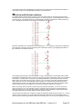
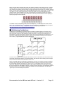
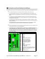
Wiring up an LCD to the ABCmaxi:
The ABCmaxi comes with an LCD connector on-board. This is a 14-pin box connector at the far-left of
the PCB. The AT90S8535 drives LCDs in 4-bit mode (the data is split into 2 4-bit “nibbles”), and so does
not need Data Lines DB0-3 to be connected.
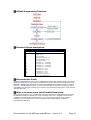
Connector Diagram
Pin #
1
2
3
4
5
6
7
8
9
10
11
12
13
14
Description
GND
VCC (5V)
Port C.1
GND
Port C.3
Port C.2
(Not Connected)
(Not Connected)
(Not Connected)
(Not Connected)
Port A.5
Port A.4
Port A.7
Port A.6
Connects to on LCD
GND
5V
RS
Contrast
E
R/W
(Not Connected)
(Not Connected)
(Not Connected)
(Not Connected)
DB5
DB4
DB7
DB6
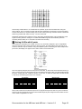
The original Maxi had three unused pads for a 10K-ohm variable resistor for the LCD contrast. Before
production, the variable resistor was removed and a zero-ohm - direct connection - resistor was placed
between the contrast pin and GND because the Maxi designer (curse him!) decided that a contrast pot
was not necessary, although it certainly is on some LCD screens, but the three pads were included. If
you have the original Maxi board, you can remove the zero-ohm resistor on the board and replace it with
a 10K-ohm trimpot. Version 2 of the Maxi board does not have this zero-ohm resistor at all and so an
external pot must be used.
Some “Extended Temperature” displays require a negative voltage on the contrast pin to function. In
these cases you will need to find your own way to get a negative voltage to the CONTRAST pin of the
LCD.
Extra LCD wiring notes:
If your programming language (or your code) does not need the LCD R/W (Read/Write Select Pin), you
can save yourself a port pin by connecting the pin straight to ground (constant write mode). It is also a
good idea to connect all the unused Data-Bit (DB) pins to ground to prevent scrambling of LCD text if
the data-bit pins are set momentarily high due to stray AC radiation.
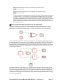
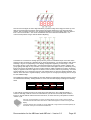
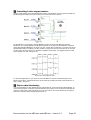
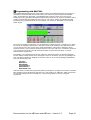
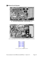
Pushbuttons can be attached to the LCD data-bit pins if you can enable and disable the LCD via
software. The pushbuttons MUST have a diode to prevent the data-bit lines from being connected
together when multiple buttons are pushed at the one time. The next image shows how to rig three
buttons.
The above example uses Port D bits 4-8, but you can use any port you wish. To read the buttons, first
disable the LCD, and send all the data-bit lines (Port D bits 4-7) high. If Port D.8 is low, no buttons are
pressed and the LCD should be re-enabled (or disabled until new text is to be sent to the LCD). In the
event of Port D.8 being high, all the data-bit pins are sent low, and then each individual pin is pulled high
and the control line (Port D.8) is read – a high value indicates a pushed button. You will also need to
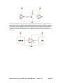
add a 1K resistor to the control line (Port D.8) to ground to act as a pull-down resistor (See next section)
or you can enable the internal pull-ups and invert the logic.
There is a brilliant and free LCD documentation available on the Internet at
http://www.mil.ufl.edu/imdl/handouts/lcd-faq.htm. This page is the equivalent of a datasheet for the
Documentation for the ABCmaxi and ABCmini – Version 5.2
Page 25