1
CHAPTER
CONTROL MODES
OF OPERATION
AND TUNING
5
In This Chapter...
Control Modes of Operation . . . . . . . . . . . . . . . . .5–2
How to Change Control Modes . . . . . . . . . . . . . . . . . . . . . . . . .5–2
Position Control Modes . . . . . . . . . . . . . . . . . . . . .5–3
Structure of Position Control Modes . . . . . . . . . . . . . . . . . . . . . .5–3
Electronic Gear Ratio . . . . . . . . . . . . . . . . . . . . . . . . . . . . . . . . . .5–4
Position Command Low-pass Filter . . . . . . . . . . . . . . . . . . . . . . .5–5
Position Loop Gain Adjustment . . . . . . . . . . . . . . . . . . . . . . . . . .5–5
Command Source of Pt Position Control Mode . . . . . . . . . . . . . .5–6
Command Source of Pr Position Control Mode . . . . . . . . . . . . . .5–7
Timing Chart of Pr Position Control Mode . . . . . . . . . . . . . . . . .5–8
Teach Position Function for Pr Absolute Position Control . . . . . .5–9
S-curve Filter for Pr Position Control . . . . . . . . . . . . . . . . . . . . . .5–9
Parameters for Absolute and Incremental Pr Control . . . . . . . . .5–10
Parameters for Index Mode Pr Control . . . . . . . . . . . . . . . . . . .5–12
Parameters for Absolute and Incremental Auto Pr Control . . . . .5–22
Velocity Control Mode . . . . . . . . . . . . . . . . . . . . .5–27
Command Source of Velocity Control Mode . . . . . . . . . . . . . . .5–27
Structure of Velocity Control Mode . . . . . . . . . . . . . . . . . . . . . .5–28
Smoothing Strategy of Velocity Control Mode . . . . . . . . . . . . .5–29
Analog Velocity Input Scaling . . . . . . . . . . . . . . . . . . . . . . . . . .5–30
Timing Chart of Velocity Control Mode . . . . . . . . . . . . . . . . . . .5–30
Velocity Loop Gain Adjustment . . . . . . . . . . . . . . . . . . . . . . . . .5–31
Resonance Suppression . . . . . . . . . . . . . . . . . . . . . . . . . . . . . . .5–31
5–1a
CHAPTER
CONTROL MODES
OF OPERATION
AND TUNING
5
In This Chapter (continued)...
Torque Control Mode . . . . . . . . . . . . . . . . . . . . .5–34
Command Source of Torque Control Mode . . . . . . . . . . . . . . .5–34
Structure of Torque Control Mode . . . . . . . . . . . . . . . . . . . . . .5–35
Smoothing Strategy of Torque Control Mode . . . . . . . . . . . . . .5–35
Analog Torque Input Scaling . . . . . . . . . . . . . . . . . . . . . . . . . . .5–36
Timing Chart of Torque Control Mode . . . . . . . . . . . . . . . . . . .5–36
Dual Control Modes Selection . . . . . . . . . . . . . . .5–37
Position / Velocity Control Mode Selection . . . . . . . . . . . . . . . .5–37
Position / Torque Control Mode Selection . . . . . . . . . . . . . . . . .5–38
Velocity / Torque Control Mode Selection . . . . . . . . . . . . . . . . .5–39
Limits . . . . . . . . . . . . . . . . . . . . . . . . . . . . . . . . . .5–40
Velocity Limit . . . . . . . . . . . . . . . . . . . . . . . . . . . . . . . . . . . . . .5–40
Torque Limit . . . . . . . . . . . . . . . . . . . . . . . . . . . . . . . . . . . . . . .5–40
Regenerative Resistor . . . . . . . . . . . . . . . . . . . . . .5–41
Built-in Regenerative Resistor . . . . . . . . . . . . . . . . . . . . . . . . . . .5–41
External Regenerative Resistor . . . . . . . . . . . . . . . . . . . . . . . . . .5–41
Electromagnetic Brake . . . . . . . . . . . . . . . . . . . . .5–43
5–1b
CHAPTER
CONTROL MODES
OF OPERATION
AND TUNING
5
In This Chapter (continued)...
Tuning Modes Overview . . . . . . . . . . . . . . . . . . .5–45
Purpose of Tuning; Why and When it is Necessary . . . . . . . . . .5–45
SureServo™ Tuning Modes Available . . . . . . . . . . . . . . . . . . . . .5–46
Tuning Modes and Their Relevant Parameters . . . . . . . . . . . . . .5–47
Monitoring System Performance . . . . . . . . . . . . . . . . . . . . . . . .5–47
Tuning Modes Details . . . . . . . . . . . . . . . . . . . . .5–48
Auto-Tuning Modes . . . . . . . . . . . . . . . . . . . . . . . . . . . . . . . . .5–48
Using Auto-Tune PI Mode . . . . . . . . . . . . . . . . . . . . . . . . . . . . .5–49
Using Auto-Tune PDFF Mode . . . . . . . . . . . . . . . . . . . . . . . . . .5–51
Using Easy-Tune Mode . . . . . . . . . . . . . . . . . . . . . . . . . . . . . . .5–53
Using Manual Tuning Mode . . . . . . . . . . . . . . . . . . . . . . . . . . .5–55
Manual Tuning Mode Details . . . . . . . . . . . . . . . . . . . . . . . . . .5–57
5–1c
Chapter 5: Control Modes of Operation and Tuning
Control Modes of Operation
SureServo drives can be programmed to provide six single and five dual modes of
operation, as selected by parameter P1.01. The mode operations and descriptions
are listed in the following table.
SureServo Control Modes of Operation
Dual Mode
Single Mode
Mode
Symbol P1.01 Description
External
Position Control
(Position - terminals)
Pt
00
Position control for the servo motor is achieved via external
pulse/count commands. Quadrature, pulse + direction, and
CW/CCW are supported.
Internal
Position Control
(Position - registers)
Pr
01
Position control for the servo motor is achieved via command
positions stored within the servo drive. Selection of the 8 possible
position preset setpoints occurs via Digital Input (DI) signals.
Velocity Control
V
02
Velocity control for the servo motor is achieved via an external
analog ±10 Vdc command signal, or via velocity setpoints stored
within the drive. Digital Inputs select either the analog signal or
one of three internal setpoints.
Internal
Velocity Control
Vz
04
Velocity control for the servo motor is achieved via velocity
setpoints stored within the controller. Selection of the 3 velocity
setpoints occurs via Digital Inputs (DI).
Torque Control
T
03
Torque control for the servo motor is achieved via an external
analog ±10 Vdc command signal or torque setpoints stored within
the drive. Digital Inputs select either the analog signal or one of
three internal preset setpoints.
Internal
Torque Control
Tz
05
Torque control for the servo motor is achieved via torque setpoints
within the controller. Selection of the 3 torque parameters occurs
via Digital Inputs (DI).
Ext. Pos. - Velocity
Pt-V
06
Either Pt or V control modes can be selected via DI signals.
Ext. Position - Torque
Pt-T
07
Either Pt or T control modes can be selected via DI signals.
Int. Pos. - Velocity
Pr-V
08
Either Pr or V control modes can be selected via DI signals.
Int. Position - Torque
Pr-T
09
Either Pr or T control modes can be selected via DI signals.
Velocity - Torque
V-T
10
Either V or T control modes can be selected via DI signals.
How to Change Control Modes
1) Disable the servo drive by removing the Servo Enable signal.
2) Adjust parameter P1-01. (Refer to the Parameters chapter for more info.)
3) After changing the parameter value, power to the drive must be cycled for
the change to take effect.
The following sections describe the operation of each control mode.
5–2
SureServo™ AC Servo Systems User Manual
2nd Ed, Rev B
08/2011
Chapter 5: Control Modes of Operation and Tuning
Position Control Modes
The position control modes (Pt or Pr mode) are used in applications requiring
precision positioning, such as index tables, slides, etc. The SureServo drive
supports two kinds of command sources in position control mode. One is an
external pulse train (Pt: Position-Terminals), and the other is internal parameter
settings (Pr: Position-Registers; the drive’s Internal Indexer function).
In order to provide a convenient position control function, the SureServo drive’s
Internal Indexer function provides eight internal preset position parameters for
position control. The selection of which position command to use comes from
three digital inputs. While this allows the inputs to select eight possible command
positions, the actual number of selectable positions is infinite since each
parameter is addressable via the Modbus interface. The Pr mode also allows for
Index Mode (to control rotary tables, tool changers, etc.) and Auto Position Mode
(for sequencing multiple moves together).
To allow the servo motor and load to operate more smoothly, the SureServo drive
also provides complete Position Spine Line (S-curve) profile for position control
mode. For closed-loop positioning, users may need to set not only the velocity
control parameters, but also the position loop gain and feed forward
compensation parameters. Three different tuning modes (Manual/Auto/Easy) allow
the user to choose simple gain set-ups or to fine-tune the servo system with
complete tuning flexibility. This chapter describes the applicability of loop gain
adjustment, feed forward compensation, and tuning technology of SureServo
systems.
Structure of Position Control Modes
Basic Block Diagram of Position Control (Pt and Pr)
Position Command
Position Command
Processing
Position Control
Block Diagram
2nd Ed, Rev B
08/2011
Speed
Loop
Current
Loop
SureServo™ AC Servo Systems User Manual
5–3
Chapter 5: Control Modes of Operation and Tuning
Basic Block Diagram of Position Command Processing
Position Command Processing
Pr Mode:
CN1
POS2-POS0
CTRG
Command
Source
P1-15
through
P1-30
Electronic
Gear Ratio
P1-44
P1-45
1) Absolute
Position Control
2) Incremental
Position Control
P1-33
S-curve
Filter
P1-34
through
P1-36
Command
Selection
P1-01
Pt Mode:
Pulse Signal
Pulse Type Selection
P1-00
Counter
Electronic Gear Ratio
P1-44, P1-45
Low-pass
Filter
P2-25
Position
Loop
The Electronic Gear Ratio (P1-44, P1-45) can be used in both Pt and Pr modes to
configure the proper scaling of input pulse signals to output motor positioning.
SureServo drives also provide a Low-pass Filter (P1-8) for Pt and Pr modes, and a
S-curve Filter (P1-34, P1-35, P1-36) for Pr mode. Explanations of these settings
follow later in this chapter.
Electronic Gear Ratio
Electronic gear ratio = (N1/M) = (P1-44)/(P1-45).
The electronic gear setting range should be (1/50) ≤ (N1/M) ≤ 200.
The Electronic Gear Ratio (EGR) is the number of output counts divided by the
number of input pulses. It allows the user to scale the high-velocity positioning
pulses coming into the drive, and is used to set some number of command counts
to a unit of measure. For example: on a linear slide application, the input pulses
can be scaled by electronic gearing so that 1 input pulse = 1 mm of travel.
Electronic Gearing can also be used to increase the velocity at which the
controller can command the motor to move. For example: Without electronic
gearing (EGR = 1), a PLC that could only output a maximum pulse stream of
5kHz, would yield a 30 rpm maximum motor velocity:
(5,000 pulse/sec)(60 sec/min)(1 count/pulse) / (10,000 count/rev) = 30 rpm.
By inserting an Electronic Gear Ratio of 100:1, the 5kHz PLC could command the
motor at a maximum of 3000 rpm. (EGR = output counts / input pulses)
(5,000 pulse/sec)(60 sec/min)(100 count/pulse) / (10,000 count/rev) = 3,000 rpm.
There are tradeoffs when using Electronic Gearing. While the above example will
allow a 5kHz PLC output to move a SureServo motor at 3000 rpm, the downside
is that the system loses resolution. While the motor still has a hardware resolution
of 10,000 individual positions per resolution, every command pulse now coming
into the SureServo drive causes the motor to increment its position by 100 motor
counts.
5–4
SureServo™ AC Servo Systems User Manual
2nd Ed, Rev B
08/2011
Chapter 5: Control Modes of Operation and Tuning
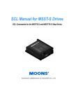
Position Command Low-pass Filter
The low pass filter (LPF) smoothes the incoming command pulses (in Pt mode),
and the command step changes (in Pr mode). This feature can be used to reduce
vibration inherent in some very rigid systems. The LPF can also smooth the motor
reaction to systems that have erratic pulse inputs (generated by encoders, sensors,
etc.). P1-08 sets the LPF, and a value of 0 disables it.
Position
Target position
Time (ms)
Low-pass Filter
P1-08
Position Loop Gain Adjustment
Before performing position control, the user should complete the velocity mode tuning,
since position loop control depends on the velocity loop. (Refer to the “Tuning
Modes” sections of this chapter for information on tuning methods.)
The position loop is adjusted by the Position Loop Proportional Gain, KPP (P2-00),
and the Position Feed Forward Gain, KFF (P2-02). Increasing KPP will increase
the response bandwidth of the position loop, and increasing KFF will reduce the
phase delay time during operation. The phase delay will approach zero when the
KFF setting is close to 100%.
(The response bandwidth is the frequency at which the system re-evaluates the
position error. Higher bandwidths yield faster output responses, while lower
bandwidths yield slower output responses.)
Since the Position Loop response is dependent upon the Velocity Loop, it is
recommended that the Velocity Loop be at least four times faster than the Position
Loop. This means that the Velocity Loop Proportional Gain, KVP (P2-04), should
be at least four times larger than the Position Loop Proportional Gain, KPP (P200).
• The Position Loop Proportional Gain (KPP) is defined as:
KPP = (2)(π)(fp) where fp is the bandwidth of the position loop response.
• The Velocity Loop Proportional Gain (KVP) is similarly defined as:
KVP = (2)(π)(fv) where fv is the bandwidth of the velocity loop response.
• So, the bandwidths should have the following relation:
fp ≤ (fv)/4.
2nd Ed, Rev B
08/2011
SureServo™ AC Servo Systems User Manual
5–5
Chapter 5: Control Modes of Operation and Tuning
Position Control
Block Diagram
Feed Forward Gain
(P2-02; KFF)
Differentiator
Position
Command
Proportional Gain
(P2-00; KPP)
Server
Motor
Position
Counter
Encoder
When the value entered into the Proportional Gain (KPP) is too great, the
bandwidth of the position loop will be too high and there will be a small phase
margin. When this happens, the motor's rotor will begin to oscillate. The motor
will continually overshoot and undershoot its command position, and will
eventually fault due to position error or overload. Decrease the value of KPP until
the rotor does not violently vibrate. A low value of KPP will cause the motor to
lose position when there is a disruption caused by the load. If there is not enough
gain, then the motor will not overcome external forces to drive the motor into its
commanded position.
Adjust the Feed Forward Gain (KFF) to reduce the dynamic position following
error. The following graphs illustrate the effects of increasing KPP and KFF.
KPP = Position Loop Proportional Gain (P2-00)
KFF = Position Feed Forward Gain (P2-02)
Position
Position
KPP
KFF
Time
Time
Command Source of Pt Position Control Mode
The command source of the Pt (Position - terminals) mode comes from an
external pulse train. Parameter P1-00 selects one of the three possible types of
pulse inputs, and the polarity of the signals. The three possible position input
types are Pulse/Direction, CW/CCW, and Quadrature. Refer to the Parameters
chapter for details.
The position command pulse inputs (terminals 36, 37, 41, 43) can be opencollector (200kpps) or line driver (500kpps). For the detailed wiring, please refer
to the “Installation and Wiring” chapter of this manual.
5–6
SureServo™ AC Servo Systems User Manual
2nd Ed, Rev B
08/2011
Chapter 5: Control Modes of Operation and Tuning
Command Source of Pr Position Control Mode
The internal positioning mode, Pr, uses the drive’s Internal Indexer for position
control. The command sources of this mode are the 16 registers P1-15 through
P1-30, which provide up to eight different command positions. Each command
position consists of one register which defines the number of complete motor
revolutions (setpoint is entered in motor revolutions), and a second register which
defines any fraction of a revolution (setpoint is entered in counts; each motor
revolution is 10,000 counts, or pulses). Parameter P1-33 selects either Absolute or
Incremental position control. Digital inputs (Position Command Select 0, 1, 2) are
used to select which preset position will be used as the target. The selected move
is initiated by the rising edge of the digital input configured as the Command
Trigger.
Pr Control Mode Position Command Selection
Position
Command
DI
PCS2
DI
PCS1
DI
PCS0
P1
0
0
0
P2
0
0
1
P3
0
1
0
P4
0
1
1
P5
1
0
0
P6
1
0
1
P7
1
1
0
P8
1
1
1
Parameters
Description
P1-15
Revolutions (±30,000)
P1-16
Counts (±10,000)
P1-17
Revolutions (±30,000)
P1-18
Counts (±10,000)
P1-19
Revolutions (±30,000)
P1-20
Counts (±10,000)
P1-21
Revolutions (±30,000)
P1-22
Counts (±10,000)
P1-23
Revolutions (±30,000)
P1-24
Counts (±10,000)
P1-25
Revolutions (±30,000)
P1-26
Counts (±10,000)
P1-27
Revolutions (±30,000)
P1-28
Counts (±10,000)
P1-29
Revolutions (±30,000)
P1-30
Counts (±10,000)
Notes:
1) PCS = Position Command Select DI function; P2-10~P2-17 settings 11~13.
2) Position Command DI status: 0 indicates DI is inactive; 1 indicates DI is active.
3) The position command is activated by an Off to On transition of the Command Trigger DI.
In Absolute Positioning (P1-33 = 0), the command positions determine an
absolute position for the motor to move to. If P1-15 = 4, and P1-16 = -5000, the
motor will proceed to an absolute position of 3½ revolutions regardless of where
the motor was previously. (Refer to the Parameters chapter of this manual for
further details.) Absolute mode is ideally suited for positioning tables, linear
slides, robotics, or other applications where the motor position is always
referenced back to a known home position.
2nd Ed, Rev B
08/2011
SureServo™ AC Servo Systems User Manual
5–7
Chapter 5: Control Modes of Operation and Tuning
In Incremental Positioning (P1-33 = 1), the same parameters of P1-15 = 4 and P116 = -5000 would cause the motor to move 3½ revolutions from it’s current
location. Incremental mode is ideal for conveyors, pull belts, or other applications
where the motor does not need to be referenced back to a single position: the
motor only needs to move a certain distance each cycle.
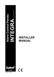
The difference between absolute and incremental position control is shown on the
graphs below. Assume the servo is homed and starts at an actual position of zero
(0). The servo is given position commands of 10 revolutions, then 20 revolutions.
If the drive is in Absolute Mode, the motor would go to an absolute position of 10
revolutions, then the motor would go to an absolute position of 20 revolutions. In
Incremental Mode, the motor would move 10 revolutions, then the motor would
move an additional 20 revolutions (ending up a total of 30 revolutions from 0).
30
Absolute
Positioning
Incremental
(relative)
Positioning
30
20
P2 =
20 turns
20
10
P1 =
10 turns
P2 =
20 turns
10
P1 =
10 turns
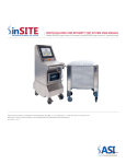
Timing Chart of Pr Position Control Mode
In Pr mode, the position command source is derived from the Digital Input signals
from CN1 (Position Command Select 0, 1, and 2, as well as the Command
Trigger). The following diagram shows the timing relationship between these DI
command signals. The Position Command Select inputs need to be held on for a
minimum of 1ms before the Command Trigger input initiates a move.
The Debounce Filter parameter, P2-09, is used to filter electrical noise and prevent
false Command Triggers. The more P2-09 is increased, the less susceptible the
system is to noise. However, increasing P2-09 too much may filter out intended
triggers.
Internal position
command
P8
P3
P2
P1
External I/O signal
1ms
Position Command Select 0
OFF
Position Command Select 1
OFF
OFF
Position Command Select 2
ON
OFF
ON
ON
ON
Command Trigger
Servo Enable
5–8
ON
SureServo™ AC Servo Systems User Manual
2ms (default)
set by P2-09
2nd Ed, Rev B
08/2011
Chapter 5: Control Modes of Operation and Tuning
Teach Position Function for Pr Absolute Position Control
A Teach Position Function is available for use in the Pr Mode with Absolute
Positioning. This function allows users to jog the motor to the desired positions
and set those positions as the Target Positions. In many cases, this method is
easier than entering numeric values directly into P1-15 ~ P1-30. Refer to the
“Teach Position Function” subsection of the “Keypad and Display Operation”
chapter for more information on the Teach Position Function.
S-curve Filter for Pr Position Control
The S-curve filter smoothes the command position in Pr mode when changing
from one position setpoint to another. Since the position commands are not
smooth and continuous, the S-curve is set to filter this step response and allow the
servo to smoothly transition from one position to another. S-curve is not used in
the Pt control mode because the acceleration, deceleration and rate of change is
usually handled by the motion controller.
The three parameters used in the S-curve filtering are Acceleration Time (P1-34),
Deceleration Time (P1-35), and S-curve Time (P1-36). The relationship between
these three settings and how they respond to a step change in command position
can be seen in the following graphs. (P1-34 determines both the acceleration and
deceleration ramps in the forward direction, and P1-35 determines accel and
decel in reverse.)
If P1-36 is set to zero, the S-curve function is disabled, and the filter is bypassed.
Commanded
Position
Time (ms)
Actual
Position
Time (ms)
Velocity
Rated velocity
Time (ms)
Dynamic
Torque
Time (ms)
P1-36 /2
P1-34* P1-36 /2
P1-36 /2 P1-34* P1-36 /2
* For reverse direction, use P1-35 in place of P1-34
S-curve characteristics and Time relationship during Acceleration; Forward Direction*
2nd Ed, Rev B
08/2011
SureServo™ AC Servo Systems User Manual
5–9
Chapter 5: Control Modes of Operation and Tuning
Parameters for Absolute and Incremental Pr Control (P1-33 = 0,1)
Generally Relevant Parameters
Pr Control Mode Relevant Parameters
Absolute and Incremental Positioning (P1-33 = 0, 1)
Parameter
Parameter Settings
P1-01
Control Mode and Output
Direction
Settings:
1: Forward = CCW rotation
101: Forward = CW rotation
P1-08
Position Command
Low-pass Filter
Setting Range: 0~1000 x10ms
P1-15 ~ P1-30
Position Commands
Setting Ranges:
±30,000 revolutions
±10,000 counts
(Refer to separate table below)
P1-33
Position Control Mode
Settings:
0: Absolute Position Mode
1: Incremental Position Mode
P1-34
Acceleration Time
Setting Range: 1~20,000 ms
Valid only if P1-36 > 0
P1-35
Deceleration Time
Setting Range: 1~20,000 ms
Valid only if P1-36 > 0
P1-36
Acceleration/Deceleration Scurve
Setting Range: 0~10,000 ms
P1-34 and P1-35 are disabled when P1-36 = 0
P1-44, P2-60 ~ P2-62
Electronic Gear Numerators
Setting Range: 0~32,767 counts
Select which numerator is active using DI (P2-10 ~ P2-17).
P1-45
Setting Range: 0~32,767 counts
Electronic Gear Denominator
P1-47
Homing Mode
Settings:
202: Forward Homing
203: Reverse Homing
P1-50
Home Position Offset (rev)
Setting Range: ±30,000 revolutions
P1-51
Setting Range: ±10,000 counts
Home Position Offset (counts)
5–10
P2-10 ~ P2-17
Digital Input Terminals
Settings:
43: Electronic Gear Numerator Selection bit 0
44: Electronic Gear Numerator Selection bit 1
P2-36 ~ P2-43
Position Velocities
Setting Range: 1~5000 rpm
(Refer to separate table below)
SureServo™ AC Servo Systems User Manual
2nd Ed, Rev B
08/2011
Chapter 5: Control Modes of Operation and Tuning
Positioning Parameters
Pr Control Mode Positioning Parameters
Absolute and Incremental Positioning (P1-33 = 0, 1)
Position
Position Command Parameters
Position Velocity Parameter
1
P1-15 revolutions; P1-16 counts
P2-36
2
P1-17 revolutions; P1-18 counts
P2-37
3
P1-19 revolutions; P1-20 counts
P2-38
4
P1-21 revolutions; P1-22 counts
P2-39
5
P1-23 revolutions; P1-24 counts
P2-40
6
P1-25 revolutions; P1-26 counts
P2-41
7
P1-27 revolutions; P1-28 counts
P2-42
8
P1-29 revolutions; P1-30 counts
P2-43
Trigger Timing Chart for Absolute and Incremental Pr Control
Refer to the “Timing Chart of Pr Position Control Mode” section of this chapter.
Pause Timing Chart for Absolute and Incremental Pr Control
If the Position Command Pause digital input becomes active while the servo motor
is moving, the motor will decelerate and stop according to the deceleration
settings of P1-35 and P1-36. When the Command Trigger DI goes active again,
the motor will move the remaining number of pulses until it reaches the target
position that was previously set.
Remaining
pulses
Move across
remaining
pulses
Speed
ΔP
Position
Command
Trigger DI
Position
Command
Pause DI
2nd Ed, Rev B
08/2011
Time
SureServo™ AC Servo Systems User Manual
5–11
Chapter 5: Control Modes of Operation and Tuning
Clear Timing Chart for Absolute and Incremental Pr Control
This Clear Command feature can be used if P2-50 is set to 2. If the Clear
Command digital input becomes active while the servo motor is moving, the
motor will decelerate and stop according to the deceleration settings of P1-35 and
P1-36. The remaining position pulses will be cleared. When the Command
Trigger DI goes active again, the motor will move from it’s present position to the
target position that is currently set.
Clear
remaining
pulses
Next moving
command
Speed
ΔP2
ΔP1
Position
Command
Trigger DI
Clear
Command
DI
Time
Parameters for Index Mode Pr Control (P1-33 = 2,3,4)
Generally Relevant Parameters for Index Mode Pr Control
Pr Control Mode Relevant Parameters
Index Mode Positioning (P1-33 = 2,3,4)
Parameter
Parameter Settings
P1-01
Control Mode and Output
Direction
Settings:
1: Forward = CCW rotation
101: Forward = CW rotation
P1-12
Torque Limit 1
Setting Range: ±300 %
(In Index Modes, the Torque Limit can be used in combination
with the Index Mode Control digital inputs to command a
“Torque Decrease” when at an Index Position.)
P1-33
Position Control Mode
Settings:
2: Forward Operation Index Mode
3: Reverse Operation Index Mode
4: Shortest Path Index Mode
P1-34
Acceleration Time
Setting Range: 1~20,000 ms
Valid only if P1-36 > 0
Table continued on next page.
5–12
SureServo™ AC Servo Systems User Manual
2nd Ed, Rev B
08/2011
Chapter 5: Control Modes of Operation and Tuning
Pr Control Mode Relevant Parameters
Index Mode Positioning (P1-33 = 2,3,4) [continued]
Parameter
Parameter Settings
P1-35
Deceleration Time
Setting Range: 1~20,000 ms
Valid only if P1-36 > 0
P1-36
Setting Range: 0~10,000 ms
Acceleration/Deceleration SP1-34 and P1-35 are disabled when P1-36 = 0
curve
P1-44
Electronic Gear Numerator
Setting Range:
0~32,767 counts
P1-45
Setting Range:
Electronic Gear Denominator 0~32,767 counts
Set the EGR numerator and denominator to the ratio of
motor turns per one turn of the load.
Example: If the load table turns once for every 100 turns
of the motor, then set P1-44 = 100, and P1-45 = 1.
P1-47
Homing Mode
Settings:
202: Forward Homing
203: Reverse Homing
P1-50
Home Position Offset (rev)
Setting Range: ±30,000 revolutions
P1-51
Setting Range: ±10,000 counts
Home Position Offset (counts)
P1-55
Maximum Velocity Limit
Setting Ranges:
0~5000 rpm (SVL-2xxx low inertia motors)
0~3000 rpm (SVM-2xxx medium inertia motors)
P2-10 ~ P2-17
Digital Input Terminals
Settings:
(Refer to Digital I/O Parameters table below for Index Mode Selections)
P2-36
Position Velocity
Setting Range: 1~5000 rpm
(If P2-36 > 3000, set P1-55 appropriately)
(This velocity applies to all Indexes.)
P2-44
Digital Output Mode
Settings:
0: Outputs function per P2-18 ~ P2-22
1: Outputs indicate current status during index mode operation
(Refer to DO Signals table below for status indications.)
P2-45
Index Mode Output
Signal Delay Time
Setting Range: 0~250 x4ms
(Applicable only if P2-44 = 1)
(This parameter delays the DO signals.)
P2-46
Index Mode Stations
Setting Range: 2~32 stations
(This parameter determines the total number of index stations on the load table,
changer, etc.)
P2-47
Position Deviation
Clear Delay Time
Setting Range: 0~250 x20ms
P2-51
Servo Enable Command
Settings:
0: Servo Enable controlled by DI per P2-10 ~ P2-17
1: Servo Enable is activated when control power is applied to servo
(Recommended in this mode only, because Index Mode Control DI handle
Fault Stop function.)
2nd Ed, Rev B
08/2011
SureServo™ AC Servo Systems User Manual
5–13
Chapter 5: Control Modes of Operation and Tuning
Digital I/O Parameters for Index Mode Pr Control
Pr Control Mode Digital I/O Parameters
Index Mode Positioning (P1-33 = 2,3,4)
DI Signal
Parameter Setting
Explanation
DI1
P2-10 = 128
Index Mode Select 0
DI2
P2-11 = 129
Index Mode Select 1
DI3
P2-12 = 130
Index Mode Select 2
DI4
P2-13 = 131
Index Mode Select 3
DI5
P2-14 = 124
Home Sensor
P2-15 = 101
Servo Enable
P2-15 = 132
Index Mode Select 4
P2-15 = 35 (use N.C. contact)
Index Mode - Manual Continuous Operation
P2-15 = 36 (use N.C. contact)
Index Mode - Manual Single Step Operation
DI7
P2-16 = 33 (use N.C. contact)
Index Mode Control 0
DI8
P2-17 = 34 (use N.C. contact)
Index Mode Control 1
DI6
DO Signal
Parameter Setting
Explanation
DO1
P2-18 = 101
Servo Ready
DO2
P2-19 = 103
At Zero Velocity
DO3
P2-20 = 109
Homing Completed
DO4
P2-21 = 105
At Position
DO5
P2-22 = 107
Active Fault
Status
Functions of Pr Index Mode DI Codes 33, 34, 35,36
Manual Index
Mode Operation
Continuous or
Single Step
DI Code 35 or 36
1
2
3
OFF
4
Notes:
ON
5–14
Index Mode
Control 1
DI Code 34
Index Mode
Control 0
DI Code 33
OFF
OFF
Decrease Torque
ON
OFF
Index Mode
OFF
ON
Home Position Mode
ON
ON
Fault Stop
x
x
don’t care
ON
OFF
CW manual operation
OFF
ON
CCW manual operation
x
x
Function
don’t care
1) The Fault Stop message will display if DI code 35 or 36 are ON when power is cycled to the
drive. If 35 or 36 then go OFF, the Fault Stop message will automatically clear.
2) The Fault Stop message will display when the status is switched directly from 2 to 3, or from
3 to 2. To prevent this situation, switch to status 1 first; i.e. 2 to 1 to 3, or 3 to 1 to 2.
SureServo™ AC Servo Systems User Manual
2nd Ed, Rev B
08/2011
Chapter 5: Control Modes of Operation and Tuning
Index Selection Using Pr Index Mode Select DI
Index Mode Index Mode Index Mode Index Mode Index Mode
Index
Select 4
Select 3
Select 2
Select 1
Select 0
Number
DI Code 32 DI Code 31 DI Code 30 DI Code 29 DI Code 28
0
0
0
0
0
1
0
0
0
0
1
2
0
0
0
1
0
3
0
0
0
1
1
4
0
0
1
0
0
5
0
0
1
0
1
6
0
0
1
1
0
7
0
0
1
1
1
8
0
1
0
0
0
9
0
1
0
0
1
10
0
1
0
1
0
11
0
1
0
1
1
12
0
1
1
0
0
13
0
1
1
0
1
14
0
1
1
1
0
15
0
1
1
1
1
16
1
0
0
0
0
17
1
0
0
0
1
18
1
0
0
1
0
19
1
0
0
1
1
20
1
0
1
0
0
21
1
0
1
0
1
22
1
0
1
1
0
23
1
0
1
1
1
24
1
1
0
0
0
25
1
1
0
0
1
26
1
1
0
1
0
27
1
1
0
1
1
28
1
1
1
0
0
29
1
1
1
0
1
30
1
1
1
1
0
31
1
1
1
1
1
32
0 = open ; 1 = closed
2nd Ed, Rev B
08/2011
SureServo™ AC Servo Systems User Manual
-
5–15
Chapter 5: Control Modes of Operation and Tuning
Pr Index Mode Indications of DO Signals
#
DO5 DO4 DO3 DO2 DO1 DO Indication
0
0
0
0
0
0
Alarm
1
0
0
0
0
1
Servo Ready
2
0
0
0
1
0
Homing Operation in Progress
3
0
0
0
1
1
Home Operation Completed
4
0
0
1
0
0
Index Position Change in Progress
5
0
0
1
0
1
Index Position 1 Attained
6
0
0
1
1
0
Index Position 2 Attained
7
0
0
1
1
1
Index Position 3 Attained
8
0
1
0
0
0
Index Position 4 Attained
9
0
1
0
0
1
Index Position 5 Attained
10
0
1
0
1
0
Index Position 6 Attained
11
0
1
0
1
1
Index Position 7 Attained
12
0
1
1
0
0
Index Position 8 Attained
13
0
1
1
0
1
Index Position 9 Attained
14
0
1
1
1
0
Index Position 10 Attained
15
0
1
1
1
1
Index Position 11 Attained
16
1
0
0
0
0
Index Position 12 Attained
17
1
0
0
0
1
Index Position 13 Attained
18
1
0
0
1
0
Index Position 14 Attained
19
1
0
0
1
1
Index Position 15 Attained
20
1
0
1
0
0
Index Position 16 Attained
21
1
0
1
0
1
Index Position 17 Attained
22
1
0
1
1
0
Index Position 18 Attained
23
1
0
1
1
1
Index Position 19 Attained
24
1
1
0
0
0
Index Position 20 Attained
25
1
1
0
0
1
Index Position 21 Attained
26
1
1
0
1
0
Index Position 22 Attained
27
1
1
0
1
1
Index Position 23 Attained
28
1
1
1
0
0
Index Position 24 Attained
29
1
1
1
0
1
Index Position 25 Attained
30
1
1
1
1
0
Index Position 26 Attained
31
1
1
1
1
1
Index Position 27 Attained
-
0 = open ; 1 = closed
-
If the DO indication switches to Servo Ready (DO = 1) during a Homing operation,
remove any abnormal conditions and then re-Home to ensure that the Home position
is correct.
5–16
SureServo™ AC Servo Systems User Manual
2nd Ed, Rev B
08/2011
Chapter 5: Control Modes of Operation and Tuning
Timing Charts of Pr Index Mode DI/DO Signals Operation
Pr Index Mode Home Search Timing Chart
In this example, Homing Mode P1-47 is set to 0202
(detect home position, decelerate and return home;
homing started by DI; stop and return to Z index mark; move forward to home sensor)
Power
Supply
DO Value
Servo Ready (01)
Home (02)
Index Position 1 (05)
Motor
Velocity
Home
Sensor DI
Z Pulse
Output Signal
Servo
Enable DI
Torque
Limit DI
P1-12 setting
P1-12 setting
Index Mode
Control 1 DI
Index Mode
Control 0 DI
2nd Ed, Rev B
08/2011
SureServo™ AC Servo Systems User Manual
5–17
Chapter 5: Control Modes of Operation and Tuning
Pr Index Mode Timing Chart using Clear Command DI
Power
Supply
Index Pos
2 (06)
Index Pos
Change
Index Pos
Change
Index Pos
6 (10)
Index Pos
Change
DO Value
P2-45
Motor
Velocity
Servo
Enable DI
Torque
Limit DI
Index Mode
Select DI Value
Index # 6
Index # 2
Index # _
P2-47
Clear
Command DI
Index Mode
Control 1 DI
Index Mode
Control 0 DI
The maximum value of P2-45 = 125 x Tminimum, where Tminimum is the minimum
time from A to B, i.e. starting to run at A and starting to run at B. (Time unit is 1 sec.)
Refer to the figure below:
A
B
T minimum
5–18
SureServo™ AC Servo Systems User Manual
2nd Ed, Rev B
08/2011
Chapter 5: Control Modes of Operation and Tuning
Pr Index Manual Mode Timing Chart using Step Forward DI
Power
Supply
Index Pos
Change
Index Pos
2 (06)
Index Pos
Change
Index Pos
3 (07)
Index Pos
Change
DO Value
P2-45
Motor
Velocity
Servo
Enable DI
Torque
Limit DI
Index Mode
Select DI
Value
Index # 2
manually step
forward
Step
Forward DI
manually step
forward
auto
running
Index Mode
Control 1 DI
Index Mode
Control 0 DI
1) The manual step forward velocity is set by parameter P2-36.
2) Set the Index Mode Control 1 DI ON before using the Step Forward DI to initiate
the move. The Index Mode Select DI should remain unchanged to prevent returning
to Index # 1 when the Step Forward operation occurs.
2nd Ed, Rev B
08/2011
SureServo™ AC Servo Systems User Manual
5–19
Chapter 5: Control Modes of Operation and Tuning
Pr Index Manual Mode Timing Chart using Manual Single Step DI
Power
Supply
Index Pos
Change
Index Pos
Change
Index Pos
Change
Index Pos
Change
DO Value
Index Pos
2 (06)
Index Pos
3 (07)
Index Pos
4 (08)
Index Pos
5 (09)
Motor
Velocity
Servo
Enable DI
Torque
Limit DI
Index Mode
Select DI
Value
Index # 2
manually
single step
Index Mode
Manual
Single Step DI
auto
running
Index Mode
Control 1 DI
Index Mode
Control 0 DI
The manual single step velocity is set by parameter P2-36.
When the Index Mode Manual Single Step DI is ON, the rising edge of the Index Mode
Control 0 DI will initiate a forward single step, and a rising edge of the Index Mode
Control 1 DI will initiate a reverse single step.
To prevent abnormal conditions, follow this procedure after the single step operation is
completed:
1) Turn the Index Mode Control 0 and 1 DI OFF.
2) Then cycle the Index Mode Manual Single Step DI from ON to OFF
5–20
SureServo™ AC Servo Systems User Manual
2nd Ed, Rev B
08/2011
Chapter 5: Control Modes of Operation and Tuning
Pr Index Manual Mode Timing Chart using Manual Continuous DI
Power
Supply
Index Pos
Change
Index Pos
Change
Index Pos
Change
Index Pos
Change
DO Value
Index Pos
2 (06)
Index Pos
3 (07)
Index Pos
4 (08)
Index Pos
5 (09)
Motor
Velocity
Servo
Enable DI
Torque
Limit DI
Index Mode
Select DI
Value
Index # 2
manually
continuous step
Index Mode
Manual
Continuous DI
auto
running
Index Mode
Control 1 DI
Index Mode
Control 0 DI
The manual continuous operation velocity is set by parameter P2-36.
When the Index Mode Manual Continuous Operation DI is ON, the servo motor will
continuously operate forward while the Index Mode Control 0 DI is ON, and will
continuously operate in reverse while the Index Mode Control 1 DI is ON.
To prevent abnormal conditions, follow this procedure after the manual continuous
operation is completed:
1) Turn the Index Mode Control 0 and 1 DI OFF.
2) Then cycle the Index Mode Manual Continuous Operation DI from ON to OFF
2nd Ed, Rev B
08/2011
SureServo™ AC Servo Systems User Manual
5–21
Chapter 5: Control Modes of Operation and Tuning
Parameters for Absolute and Incremental Auto Pr Control
(P1-33 = 5,6)
Internal Absolute and Incremental Auto Position Modes allow the SureServo Drive
to be easily programmed to step through a series of eight unique indexes (moves).
They are the same indexes available in the standard Pr mode (Parameters P1-15 ~
P1-30). In normal Pr mode (P1-33 = 00 or 01), a controller must select each
individual index through a binary combination of Digital Inputs. In Auto Index
Position Mode (P1-33 = 05 or 06), the drive will step itself through a series of
indexes (moves). Each index can be triggered either by Digital Inputs (Step
Forward or Step Reverse), or can be set to automatically start a set period of time
after the preceding index has completed. Auto Position Mode is ideal for
applications where the sequence of motions for the servo will not change. (The
actual command positions can be changed via Modbus).
The following instructions assume some familiarity with the SureServo system.
Please read the rest of this chapter and the QuickStart Guide (Appendix A) before
attempting to program the drive for Auto Position Control.
WARNING: Always start any new servo setup with the motor shaft disconnected from
the load. This could possibly save machinery or personnel from serious damage.
DISCONNECT THE LOAD. Always wire an E-Stop circuit into the power feed for the
drive. DO NOT rely on the Fault Stop digital input. Always disconnect the main
incoming power for emergency stop conditions. (Control power can remain ON.)
Instructions for Absolute and Incremental Auto Position Control
1) Set P2-08 to 10. This will reset the drive to factory defaults.
2) Cycle power.
3) Set P1-31 to the correct motor code.
4) Set P1-33 to the correct Position Control Mode.
P1-33 = 5; Absolute Auto Position Mode
P1-33 = 6; Incremental Auto Position Mode
5) Set P1-01 to the correct Control Mode.
P1-01 = 00001; Pr Position Control Mode (command setpoints via internal
registers)
6) Set the parameters for position, velocity, and dwell time. The position setpoints
will either be incremental distances or absolute positions depending on the
setting of P1-33. The velocity setpoints correspond to the appropriate indexes.
The accompanying dwell times determine how many milliseconds will elapse
between each move while the Step Forward and Step Reverse commands are
constantly being issued, or when the Auto Indexing (continuous steps) Mode is
selected. If the dwell time for any individual move is 0ms, that move will be
bypassed in the sequence of operations.
5–22
SureServo™ AC Servo Systems User Manual
2nd Ed, Rev B
08/2011
Chapter 5: Control Modes of Operation and Tuning
Pr Control Mode Positioning Parameters
Absolute and Incremental Auto Positioning (P1-33 = 5, 6)
Position
Position Command
Parameters
Position Velocity
Dwell Time
Parameter
Parameter (x10ms)
Index 1 P1-15 revolutions; P1-16 counts
P2-36
P2-52
Index 2 P1-17 revolutions; P1-18 counts
P2-37
P2-53
Index 3 P1-19 revolutions; P1-20 counts
P2-38
P2-54
Index 4 P1-21 revolutions; P1-22 counts
P2-39
P2-55
Index 5 P1-23 revolutions; P1-24 counts
P2-40
P2-56
Index 6 P1-25 revolutions; P1-26 counts
P2-41
P2-57
Index 7 P1-27 revolutions; P1-28 counts
P2-42
P2-58
Index 8 P1-29 revolutions; P1-30 counts
P2-43
P2-59
7) Set P1-34, P1-35, P1-36 for Acceleration, Deceleration, and S-curve. Without
setting these parameters, the drive may fault when a move is first intitiated.
Acceleration and Deceleration are ignored unless the S-Curve parameter is set to
a non-zero amount.
P1-36 defaults to 0 when the drive is set to factory defaults. Without changing this
parameter setting, the drive may fault when movement is initiated (a value of zero
assumes instantaneous acceleration and deceleration).
8) Configure the Digital Inputs. Define the following functions for your inputs. (The
following table is an example only. See the Parameters chapter for more
information on changing the inputs' definitions and states [normally open vs.
normally closed]).
Pr Control Mode DI Function Parameters
Absolute and Incremental Auto Positioning (P1-33 = 5, 6)
Digital DI Function
Input Parameter
2nd Ed, Rev B
Parameter
Function Description
Setting
DI1
P2-10
124
Home Sensor
DI2
P2-11
121
Fault Stop
DI3
P2-12
0
DI4
P2-13
127
Start Home Move Trigger
DI5
P2-14
140
Step Forward
DI6
P2-15
142
Auto Position Mode
DI7
P2-16
139
Step Reverse
DI8
P2-17
101
Servo Enable
08/2011
Input Disabled
SureServo™ AC Servo Systems User Manual
5–23
Chapter 5: Control Modes of Operation and Tuning
9) Set P2-44, Digital Output Mode, to the desired setting. A value of 00 sets the
Digital Outputs to function according to the settings in P2-18 ~ P2-22. A value of
01 sets the Digital Outputs to indicate the current position during index mode
operation. They will generate the following binary code as status for an external
controller. This is useful to check to see that the servo has arrived at the
appropriate index point. This binary code is shown in P4-09, and can also be
read via Modbus. (Refer to the “MODBUS Communications” chapter of this
manual for information regarding Modbus communication.)
Pr Control Mode DO Signals Indications Parameters
Absolute and Incremental Auto Positioning (P1-33 = 5, 6)
#
DO5 DO4 DO3 DO2 DO1 DO Indication
0
0
0
0
0
0
Alarm
1
0
0
0
0
1
Servo Ready
2
0
0
0
1
0
Homing Operation in Progress
3
0
0
0
1
1
Home Operation Completed
4
0
0
1
0
0
Index Position Change in Progress
5
0
0
1
0
1
Index Position 1 Attained
6
0
0
1
1
0
Index Position 2 Attained
7
0
0
1
1
1
Index Position 3 Attained
8
0
1
0
0
0
Index Position 4 Attained
9
0
1
0
0
1
Index Position 5 Attained
10
0
1
0
1
0
Index Position 6 Attained
11
0
1
0
1
1
Index Position 7 Attained
12
0
1
1
0
0
Index Position 8 Attained
-
0 = open ; 1 = closed
-
10) Configure P1-47, Homing Mode (if necessary). The drive will automatically
power up at position zero. If your application needs a homing reference, see
P1-47 for configuration. A value of 0202 in P1-47 will configure the drive to
look for an external home command signal. When the Home Sensor Digital
Input is triggered, the drive will search for an external (DI) Home Sensor. When
the home sensor is found, the drive will reverse and proceed to the next motor
encoder Z-pulse. Your application may vary.
P1-47 = 0202; Home to sensor when home command is issued.
11) Cycle power to the drive. This will allow all changes to take effect. The drive
will now follow Step Forward/Step Reverse Commands and the Start Home
Move Trigger Command.
When the drive is in Absolute Auto Position Mode (using absolute references for
command position), the drive will not Step Reverse to zero position unless Position
Command 1 (P1-15 and P1-16) is equal to zero.
5–24
SureServo™ AC Servo Systems User Manual
2nd Ed, Rev B
08/2011
Chapter 5: Control Modes of Operation and Tuning
An anomaly may occur when not all indexes are programmed (ie: Dwell Times = 0ms
in P2-59, etc.). If the master controller (PLC) commands a Step Forward past the last
valid position, the master controller will have to issue two Step Reverse commands
before movement will occur. (Trying to Step past a valid Step 8 does not cause this
anomaly; only one Step Reverse will initiate motion.)
Do not issue JOG or Home commands while Step Forward, Step Reverse, or Auto Index
Position motions are occurring. The drive will halt the current move and immediately
begin the commanded Jogging or Homing.
Command and Response Example for
Absolute and Incremental Auto Pr Control
When in Internal (Pr) Auto Position Control Mode, the outputs can set to output a
binary code to an external controller (PLC, etc.) Setting P2-44 to 1 will cause the
outputs to follow the binary code shown previously. When in this state, the
external controller can monitor the status of the SureServo Drive, not only for
faults, but also for the position of the motor. The following is an example of the
state of the drive outputs when P2-44 = 1. This can be monitored via DI signals
going to an external controller's inputs, or can be read via Modbus from
parameter P4-09; Modbus hex address 0x0409 ("1033" in 0-based Modbus
addressing, "41034" in 1-based Modbus addressing).
This example is for Absolute Auto Position Mode (P1-33 = 5). All Indexes
represent an absolute command position for the drive to go to. If using
Incremental Auto Position Mode (P1.33 = 6), all Indexes will be lengths of moves.
All other logic remains the same.
Example: Absolute and Incremental Pr Auto Positioning
Action or Status
P4-09 (DO Status) Value
Drive is in Fault condition
0 - Alarm
Drive is powered up with no Faults
1 - Servo Ready
Start Home Move Trigger DI is triggered; homing sequence begins 2 - Homing Operation in Progress
Home sequence completes
3 - Home Operation Completed
Return to Index 1 DI is triggered; move begins from Home to
Index Position 1
4 - Index Position Change in Progress
Motor arrives at Index Position 1
5 - Index Position 1 Attained
Step Forward DI is triggered; move begins to Index Position 2
4 - Index Position Change in Progress
Motor arrives at Index Position 2
6 - Index Position 2 Attained
Step Forward DI is triggered; move begins to Index Position 3
4 - Index Position Change in Progress
Motor arrives at Index Position 3
7 - Index Position 3 Attained
Step Reverse DI is triggered; move begins to Index Position 2
4 - Index Position Change in Progress
Motor arrives at Index Position 2
6 - Index Position 2 Attained
Step Reverse DI is triggered; move begins to Index Position 1
4 - Index Position Change in Progress
Motor arrives at Index Position 1
5 - Index Position 1 Attained
2nd Ed, Rev B
08/2011
SureServo™ AC Servo Systems User Manual
5–25
Chapter 5: Control Modes of Operation and Tuning
With this type of response behavior, it is very simple for a PLC to accurately
maintain the drive status and motor location; even if no communication (Modbus,
etc.) is available in the PLC. The DO (digital outputs) will relay the drive status
(faulted, moving, current position, etc.). Remember, if any of the dwell times are
zero, the corresponding index will be invalid (it will be skipped by the internal
sequencer whenever STEP FWD, STEP REV, or Auto Index Mode are active).
If running Auto Index Mode, the sequence of events when Auto Index Position
Mode DI is ON will be Index 1, Dwell Time 1, Index 2, Dwell Time 2, ….Index 7,
Dwell Time 7, Index 8, Dwell Time 8, Index 1, Dwell Time 1, Index 2, Dwell
Time 2, etc.
If running Step FWD/Step REV, then Stepping FWD past Index 8 will result in no
motion. Stepping Rev past Index 1 also will result in no motion.
5–26
SureServo™ AC Servo Systems User Manual
2nd Ed, Rev B
08/2011
Chapter 5: Control Modes of Operation and Tuning
Velocity Control Mode
The Velocity Control modes (V and Vz) are used on applications of precision
speed control, such as CNC machines, conveyor speed matching, etc. Typically,
the command signal is generated from an analog motion controller (a CNC
controller, for example), or from a speed sensing device (when matching one
conveyor speed to another, etc.). The SureServo drive supports two kinds of
command sources in Velocity Control mode; (1) external analog ±10Vdc signal
and (2) internal velocity parameters.
The V mode (external) allows the user to select either the analog signal or one of
three internal velocity settings. The Vz mode (internal) allows only the use of
internal setpoints for velocity commands (a command of zero, plus three velocity
setpoints). Both Velocity modes use two Digital Inputs to select which velocity
command (analog and/or preset) is active.
In order for the SureServo motor and load to operate smoothly, the servo drive
provides complete S-curve profiling in velocity control mode. The SureServo drive
provides closed loop gain adjustment and an integrated PI controller. Also, the
servo drive provides three modes of tuning technology (Manual/Auto/Easy).
Command Source of Velocity Control Mode
Velocity command sources:
1) External analog signal; external analog voltage input, -10V to +10V.
2) Internal parameter: P1-09 to P1-11.
Velocity Control Mode Command Source
DI Signal
Velocity
1
Command VCS1(15) 1VCS0(14)
Velocity #1
0
0
Velocity #2
0
1
Velocity #3
1
0
Velocity #4
1
1
Command Source
Mode
V
Vz
2
External AI
Content
Range
Voltage Vref to GND
±10V
Zero Velocity Velocity Command is 0
Internal parameters
0
P1-09
±5000 rpm
P1-10
±5000 rpm
P1-11
±5000 rpm
Note 1: VCS = “Velocity Command Select” DI function; P2-10~P2-17 settings 14 (VCS0) and 15
(VCS1).
Note 2: When using AI velocity command, set P4-22 (Analog Velocity Input Offset) to trim the
signal so that a 0V command results in no motor rotation.
If the Velocity Command Select digital inputs (VCS0 and VCS1) are both = 0, and
the control mode of operation is Vz, then the velocity command is 0. Therefore, if
users do not need to use analog voltage as a velocity command, they can choose
Vz mode and avoid the zero point drift problem of analog voltage signals. If the
current control mode of operation is V, then the command is the analog voltage
between V-REF and GND. The setting range of the input voltage is from -10V to
+10V and the corresponding rotation velocity is adjustable (see parameter P1-40).
2nd Ed, Rev B
08/2011
SureServo™ AC Servo Systems User Manual
5–27
Chapter 5: Control Modes of Operation and Tuning
When at least one of the Velocity Command Select inputs is enabled, the velocity
command is the corresponding internal parameter shown in the table above. The
command is valid (enabled) immediately after either VCS0 or VCS1 is changed. It
is not necessary to trigger the Command Trigger digital input (as in Pr mode).
Note: The velocity commands are used as the velocity limit commands in the
Torque Control modes (T or Tz mode).
Structure of Velocity Control Mode
Velocity Control Mode Basic Structure:
Velocity Command
Velocity Command
Processing
Velocity
Estimator
Resonant Suppression
Block Diagram
Velocity Control
Block Diagram
Torque
Limiter
Current
Loop
In the figure above, the velocity command processing is used to select the
command source of velocity control, including maximum rotation speed of analog
velocity command selection (parameter P1-40) and S-curve filter of velocity
control. The velocity control block diagram is used to manage the gain
parameters of the servo drive, and to calculate the current input supplied to the
servo motor. The resonance suppression block diagram is used to suppress the
resonance of mechanical system.
The function and structure of velocity command processing is shown as the figure
below:
Discrete Inputs
VCS0(14), VCS1(15)
Velocity Command Processing
Command Source:
Internal Parameter
Command Source:
External
Analog Signal
S-curve
Filter
P1-34
through
P1-36
Internal
Parameter
P1-09
through
P1-11
A/D
Converter
Analog Full
Scale Velocity
Command
P1-40
Analog
Velocity
Input
Offset
P4-22
Analog
Command
Filter
P1-34
~P1-36
Command
Selection
P1-01
Low-pass
Filter
P1-06
Analog Signal
The command source is selected according to the state of VCS0, VCS1 and
parameter P1-01 (V or Vz). The S-curve and low-pass filters smooth the transition
from one velocity setpoint to another.
5–28
SureServo™ AC Servo Systems User Manual
2nd Ed, Rev B
08/2011
Chapter 5: Control Modes of Operation and Tuning
Smoothing Strategy of Velocity Control Mode
S-curve Filter and Analog Command Filter
The S-curve Filter is a combination of three parameters that can smooth the
effects of sudden changes in velocity when a new internal Velocity Command is
selected. Using the S-curve filter allows a more gradual output response to
sudden command changes. This reduces the mechanical resonance and noise
that would otherwise be caused by friction and inertia during sudden velocity
changes, and improves the servo motor performance during acceleration,
operation, and deceleration.
The parameters that compose the S-curve filter are the Accel/Decel S-curve
constant (P1-36), Acceleration Time constant (P1-34), and Deceleration Time
constant (P1-35).
If P1-36 is set to zero, the Accel/Decel S-curve function is disabled.
S-curve Characteristics
and Time Relationship
Speed (Velocity)
Acceleration
Rated Velocity
Deceleration
Time (ms)
0
Dynamic Torque
0
Time (ms)
P1-36 /2
P1-34
P1-36 /2
P1-36 /2
P1-35
P1-36 /2
S-curve Characteristics and Time Relationship
Analog Velocity Command Low-pass Filter (AVCLF)
The Analog Velocity Command Low-pass Filter is used to eliminate high frequency
response and electrical interference from the analog input signal, and it smoothes
the output response regardless of whether the command source is internal or
external. The AVCLF consists of the same three parameters as does the S-curve
Filter (P1-34, P1-35, P1-36), and also functions similarly to the S-curve Filter.
If P1-06 is set to zero (0), the
Analog Velocity Command Lowpass Filter is disabled.
The P1-06 filter smoothes the
output response from internal
parameter and from analog input
command sources.
2nd Ed, Rev B
08/2011
Speed/Velocity
Target Speed
Time (ms)
P1-06
SureServo™ AC Servo Systems User Manual
5–29
Chapter 5: Control Modes of Operation and Tuning
Analog Velocity Input Scaling
The analog voltage between V_REF (analog Velocity Command input) and GND
(CN1 pins 12, 13, 19, 44) determines the motor Velocity Command. Parameter
P1-40 (Analog Full Scale Velocity Command/Limit) adjusts the velocity control
range and the slope of its ramp. For example, when P1-40 is set to 3000, the
maximum rotation speed of the analog velocity command (10V) is 3000 rpm, as
shown below.
5000rpm
The velocity control ramp is
determined by parameter P1-40
3000rpm
-10
-5
5
10
Analog Input Voltage (V)
-3000rpm
-5000rpm
• Velocity Command = ((P1-40)/10) [(Input V) - ((P4-22)/1000)]; Limit ±(P1-40)
P4-22 (Analog Velocity Input Offset) can be used to establish an offset so that zero
velocity does not occur at zero input voltage. A 0~10V input can be used for
bidirectional control.
Timing Chart of Velocity Control Mode
Velocity
Commands
#4
Internal
#2
External analog
voltage or zero (0)
External
DI signal
#3
#1
Velocity Command Select 0
OFF
Velocity Command Select 1
OFF
Servo On
ON
OFF
ON
ON
ON
1) When Velocity Control Mode is Vz, the velocity command #1=0.
2) When velocity control mode is V, the velocity command #1 is external analog
voltage input.
5–30
SureServo™ AC Servo Systems User Manual
2nd Ed, Rev B
08/2011
Chapter 5: Control Modes of Operation and Tuning
Velocity Loop Gain Adjustment
The function and structure of velocity control mode is shown below:
Velocity Control Block Diagram
Feed Forward Gain
(P2-07; KVF)
Differentiator
Proportional Gain
(P2-04; KVP)
Integral Gain
(P2-06; KVI)
Integrator
Velocity
Estimator
Encoder
The gain of SureServo drives can be adjusted using any one of three tuning
modes: 1) Manual, 2) Auto, or 3) Easy. Refer to the “Tuning Modes” section of
this chapter for more details on these tuning modes.
Resonance Suppression
Resonance of the mechanical system may occur due to excessive system stiffness
or frequency response. However, this kind of resonance condition can be
improved, suppressed, or even eliminated by using the Low-pass Filter (P2-25) and
the Notch Filter (P2-23 & P2-24).
Resonance Suppression Block Diagram
Differentiator
Feed Forward Gain
(P2-07)
Current
Sensor
PI Controller
(P2-04, P2-06)
Current
Controller
Low-pass Filter
(P2-25)
Notch Filter
(P2-23, P2-24)
Velocity Estimator
2nd Ed, Rev B
08/2011
PWM
Torque
Load
Encoder
SureServo™ AC Servo Systems User Manual
5–31
Chapter 5: Control Modes of Operation and Tuning
Low-pass Filter
The Low-pass Filter reduces resonance effects which can cause motor vibration.
The figure below shows the resonant open loop gain.
Gain
X = Low-pass
Frequency
X
0dB
Frequency
The Low-pass Filter eliminates any response from frequencies above the low-pass
frequency. Since the low-pass frequency (X) is inversely proportional to the Lowpass Filter (parameter P2-25), the value of X becomes smaller as P2-25 is
increased (see the figure below). The vibration causing resonant condition
improves; however, the frequency response and phase margin decrease.
Gain
X = Low-pass
Frequency
X
0dB
5–32
SureServo™ AC Servo Systems User Manual
Frequency
2nd Ed, Rev B
08/2011
Chapter 5: Control Modes of Operation and Tuning
Notch Filter
If the resonant frequency can be determined, then use the Notch Filter (parameters
P2-23 & P2-24) to eliminate the resonance, and reduce motor vibration.
However, if the resonant frequency is outside of the Notch Filter range
(50~1000Hz & 0~32dB), then use the Low-pass Filter to improve the resonance.
To use the Notch Filter, first determine the resonant frequency of the system, and
then set P2-23 to that frequency. Then adjust P2-24 upward until resonance is
suppressed.
Gain
Notch Filter
P2-24
Frequency
P2-23
P2-24 should be adjusted only as high as needed to suppress the resonance. An
excessive attenuation setting will result in degraded system performance.
2nd Ed, Rev B
08/2011
SureServo™ AC Servo Systems User Manual
5–33
Chapter 5: Control Modes of Operation and Tuning
Torque Control Mode
The Torque Control Modes (T or Tz) are useful for applications of torque control,
such as printing machines, spinning machines, twisters, etc. The SureServo drive
supports two types of command sources in the Torque Control mode: (1) external
analog signal, and (2) internal parameters. The external analog signal is from an
external voltage input on the CN1 connector, and the internal parameters are P112 through P1-14.
Command Source of Torque Control Mode
Torque command Source:
1) External analog signal: External analog voltage input, -10V to +10V.
2) Internal parameter: P1-12 through P1-14.
Selection of the torque command source is determined by the CN1 connector
digital inputs that are configured as “Torque Command Select 0” (TCS0) and
“Torque Command Select 1” (TCS1) as shown below:
Torque Control Mode Command Source
Torque
Command
1
DI Signal
TCS1(17) 1 TCS0(16)
Torque #1
0
0
Torque #2
0
1
Torque #3
1
0
Torque #4
1
1
Command Source
Mode
T
Tz
2
Content
Range
External AI
Voltage Tref to GND
±10V
None
Torque Command is 0
0
P1-12
±300%
P1-13
±300%
P1-14
±300%
Internal parameters
Note 1: TCS = “Torque Command Select” DI function; P2-10~P2-17 settings 16 (TCS0) and 17
(TCS1).
Note 2: When using AI torque command, set P4-23 (Analog Torque Input Offset) to trim the
signal so that a 0V command results in no motor rotation.
If TCS0=TCS1=0 (OFF), and the control mode is Tz, then the torque command is
zero. Therefore, if the analog voltage input is not to be used as the torque
command, then the Tz control mode can be used to avoid the zero point drift
problem with analog voltage signals. If TCS0 = TCS1 = 0, and the control mode is
T, then the torque command is the analog voltage between the T_REF analog input
and GND (CN1 pins 12, 13, 19, 44). The setting range of the input voltage is
from -10V to +10V, and the corresponding torque is adjustable using parameter
P1-41.
1) When TCS0 and TCS1 change, the new torque command takes affect immediately.
2) The P1-12~P1-14 Torque Commands are used as Torque Limit commands in both
position and velocity control modes (Pr, Pt, V, and Vz).
5–34
SureServo™ AC Servo Systems User Manual
2nd Ed, Rev B
08/2011
Chapter 5: Control Modes of Operation and Tuning
Structure of Torque Control Mode
Basic Structure:
Torque Command
Torque Command
Processing
Resonant Suppression
Block Diagram
Velocity
Loop
Output Torque
Current Control
Block Diagram
Current Sensor
In the figure above, the Torque Command processor is used to select the
command source of torque control as described in the previous and following
sections, including the Analog Full Scale Torque Command (P1-41), and the
smoothing strategy of the torque control mode. The current control block diagram
is used to manage the gain parameters of the servo drive and to instantaneously
calculate the current input provided to motor.
The function and structure of torque command processing is shown below:
Discrete Inputs
TCS0(16), TCS1(17)
Torque Command Processing
Internal
Parameter
P1-12
through
P1-14
Command Source:
Internal Parameter
Command Source:
External Analog Signal
A/D
Converter
Analog Full
Scale Torque
Command
P1-41
Analog
Torque Input
Offset
P4-23
Command
Selection
P1-01
Low-pass
Filter
P1-07
Analog Signal
Smoothing Strategy of Torque Control Mode
The P1-07 Analog Torque Command
Low-pass Filter smoothes the
incoming analog torque command.
Target
Torque
If P1-07 is set to zero, the smoothing
function is disabled.
Time
P1-07
2nd Ed, Rev B
08/2011
SureServo™ AC Servo Systems User Manual
5–35
Chapter 5: Control Modes of Operation and Tuning
Analog Torque Input Scaling
The analog voltage between the T_REF terminal (analog Torque Command input)
and GND (CN1 pins 12, 13, 19, 44) determines the motor Torque Command.
Parameter P1-41 (Analog Full Scale Torque Command/Limit) adjusts the torque
control ramp and its range. For example, when P1-41 is set to 100, the maximum
torque of the analog torque command (10V) is 100% of rated torque, as shown
below. If the input voltage decreases to 5V, then the analog torque command
decreases to 50% of rated torque.
P1-41
300%
The torque control ramp is
determined by parameter P1-41
100%
-10
-5
5
10
Torque Command
Analog Input Voltage (V)
-100%
-300%
• Torque Command = ((P1-41)/10) [(Input V) - ((P4-23)/1000)]; Limit ±(P1-41)
P4-23 (Analog Torque Input Offset) can be used to establish an offset so that zero
torque does not occur at zero input voltage. A 0~10V input can be used for
bidirectional control.
External
DI signal
Torque
Commands
Timing Chart of Torque Control Mode
#4
Internal
#3
#2
External analog
voltage or zero (0)
#1
Torque Command Select 0
Torque Command Select 1
Servo On
OFF
OFF
ON
OFF
ON
ON
ON
1) When Torque Control Mode is Tz, the torque command #1=0.
2) When Torque Control Mode is T, the torque command #1 is external analog voltage
input.
5–36
SureServo™ AC Servo Systems User Manual
2nd Ed, Rev B
08/2011
Chapter 5: Control Modes of Operation and Tuning
Dual Control Modes Selection
The dual control modes allow SureServo systems to switch between predetermined control modes while the servo is enabled. For example, if an
application requires both Velocity control and Torque control, P1-01 can be set to
10 to allow a digital input to select between these two control modes. The
available dual modes are shown below:
Selection of Dual Control Modes
Dual Mode
Modes P1-01 DI Setting
Available Setting P2-10~P2-17
Description
Pt-V
06
18
Either V or Pt control mode selected by DI (0=V; 1=Pt)
Pt-T
07
20
Either T or Pt control mode selected by DI (0=T; 1=Pt)
Pr-V
08
18
Either V or Pr control mode selected by DI (0=V; 1=Pr)
Pr-T
09
20
Either T or Pr control mode selected by DI (0=T; 1=Pr)
V-T
10
19
Either V or T control mode selected by DI (0=V; 1=T)
Note: If a digital input is not configured for the Mode Select function, the default mode (0) in each dual mode
will be used.
Position / Velocity Control Mode Selection
Pt-V Mode / Pr-V Mode:
The command source of Pt-V mode is defined from external digital inputs. The
command source of Pr-V mode is from the internal Position Command parameters
P1-15 through P1-30. The velocity command can be the external analog voltage
input (AI) or the internal Velocity Command parameters P1-09 to P1-11.
The velocity and position mode switching is controlled by the Position/Velocity
Mode Select (PVMS) DI signal. The selection will be more complicated when the
position of Pr-V mode and velocity command are both selected through DI
signals.
The timing chart of position/velocity control mode selection is shown below:
Position / Velocity Mode Selection
Digital Inputs
Command Trigger
Position/Velocity 1 = Position Mode
Mode Select
0 = Velocity Mode
Postion Command
Select 0, 1, 2
Don't Care
VALID
Don't Care
Velocity Command
Select 0,1
VALID
Don't Care
VALID
Position Control Mode
Velocity Control Mode
Velocity Control Mode
2nd Ed, Rev B
08/2011
SureServo™ AC Servo Systems User Manual
5–37
Chapter 5: Control Modes of Operation and Tuning
When the PVMS DI is OFF, the drive is in Velocity Mode. The velocity command
is then selected by the Velocity Command Select DI, and the Command Trigger is
ignored.
When the PVMS DI switches to ON, the drive switches to Position Mode. In this
mode, the position command is not determined until there is a rising edge of the
Command Trigger DI, so the motor stops running. When the drive receives a
rising edge of the Command Trigger DI, the Position Command is selected by the
Position Command Select DI, and the motor immediately moves to the
determined position.
When the PVMS DI switches back to OFF, the drive immediately switches back to
Velocity Mode. For more information regarding the relationships between the DI
signals and selected commands in each mode, refer to the particular single mode
sections of this chapter.
Position / Torque Control Mode Selection
Pt-T Mode / Pr-T Mode:
The position command source of Pt-T mode is from external digital inputs. The
position command source of Pr-T mode is from the internal Position Command
parameters P1-15 through P1-30. In both modes, the torque command can be the
external analog Torque Command signal, or the internal Torque Command
parameters P1-12 through P1-14.
The position and torque mode switching is controlled by the Position/Torque
Mode Select (PTMS) DI signal. The selection will be more complicated when the
position of Pr-T mode and torque command are both selected through DI signals.
The timing chart of position/torque control mode selection is shown below:
Pr Position / Torque Control Mode Selection
Digital Inputs
Command Trigger
Position/Torque
Mode Select
1 = Position Mode
0 = Torque Mode
Postion Command
Select 0,1,2
Don’t Care
VALID
Don’t Care
Torque Command
Select 0,1
VALID
Don’t Care
VALID
Torque control mode
Position control mode
Torque control mode
When the PTMS DI is OFF, the drive is in Torque Mode. The torque command is
then selected by the Torque Command Select DI, and the Command Trigger is
disabled.
5–38
SureServo™ AC Servo Systems User Manual
2nd Ed, Rev B
08/2011
Chapter 5: Control Modes of Operation and Tuning
When the PTMS DI switches to ON, the drive switches to Position Mode. In Pr-T
mode, the position command is not determined until there is a rising edge of the
Command Trigger DI, so the motor stops running. When the drive receives a
rising edge of the Command Trigger DI, the Position Command is selected by the
Position Command Select DI, and the motor immediately moves to the
determined position. In the Pt-T mode, the drive immediately responds to any
high speed pulse inputs.
When the PTMS DI switches back to OFF, the drive immediately switches back to
Torque Mode. For more information regarding the relationships between the DI
signals and selected commands in each mode, refer to the particular single mode
sections of this chapter.
Velocity / Torque Control Mode Selection
V-T Mode:
In the Velocity Mode, the velocity command can be the external analog voltage
input (AI), or it can be the internal Velocity Command parameters (P1-09 to P111) combined with the Velocity Command Select DI.
Similarly, in the Torque Mode, the torque command can be the external analog
voltage input (AI), or it can be the internal Torque Command parameters (P1-12 to
P1-14) combined with the Torque Command Select DI.
The Velocity/Torque Mode Select (VTMS) DI switches the drive between the
velocity and torque modes.
The timing chart of velocity/torque control mode selection is shown below:
Digital Inputs
Velocity / Torque Control Mode Selection
Velocity/Torque
Mode Select
1 = Torque Mode
0 = Velocity Mode
Velocity Command
Select 0,1
Don't Care
VALID
Don't Care
Torque Command
Select 0,1
VALID
Don't Care
VALID
Torque Control Mode
Velocity Control Mode
Torque Control Mode
When the VTMS DI is ON, the drive is in Torque Mode, and the torque command
is then selected by the Torque Command Select DI.
When the VTMS DI switches to OFF, the drive switches to Velocity Mode. In this
mode, the velocity command is selected by the Velocity Command Select DI, and
the motor rotates immediately following the command.
When the VTMS DI switches to back to ON, the drive immediately switches back
to Torque Mode. For more information regarding the relationships between the DI
signals and selected commands in each mode, refer to the particular single mode
sections of this chapter.
2nd Ed, Rev B
08/2011
SureServo™ AC Servo Systems User Manual
5–39
Chapter 5: Control Modes of Operation and Tuning
Limits
Velocity Limit
The maximum velocity can be limited by using parameter P1-55 (Maximum
Velocity Limit) in ALL control modes.
The velocity limit only can be used in torque mode (T mode) to limit the servo
motor velocity. When the torque command is the external analog voltage input,
there should be surplus DI signals that can be configured as Velocity Command
Select inputs used to select Velocity Limits (P1-09~P1-11). If there are not enough
DI signals, then the external voltage input can be used as Velocity Limit. When
the setting value of the least significant digit in P1-02 is set to 1, the Velocity Limit
function is activated.
The timing chart of Velocity Limit is shown below:
P1-02 Velocity Limit
Least Significant Digit
Velocity Command
Select DI 0,1
INVALID
VALID
Command Source Selection of Velocity Limit
Torque Limit
The torque limit only can be used in Position Mode (Pt and Pr modes) and
Velocity Mode (V mode) to limit the output torque of the servo motor. When the
position and velocity commands are the external analog voltage input, there
should be surplus DI signals that can be configured as Torque Command Select
inputs used to select Torque Limits (P1-12~P1-14). If there are not enough DI
signals, then the external voltage analog input can be used as Torque Limit. When
the setting value of the second least significant digit in P1-02 is set to 1, the
Torque Limit function is activated.
The timing chart of Torque Limit is shown below:
P1-02 Torque Limit
2nd Least Significant Digit
Torque Command
Select DI 0,1
INVALID
VALID
Command Source Selection of Torque Limit
5–40
SureServo™ AC Servo Systems User Manual
2nd Ed, Rev B
08/2011
Chapter 5: Control Modes of Operation and Tuning
Regenerative Resistor
Built-in Regenerative Resistor
At the point where the load starts driving the servo motor, instead of vice-versa,
the motor becomes a generator instead of a motor. The servo systems needs to
dissipate the extra energy that is being generated, and it does that through a
regenerative resistor. SureServo drives provide a built-in regenerative resistor, and
have the capability to connect an external resistor in case more regenerative
capacity is needed.
The following table shows the specifications of the servo drive's built-in
regenerative resistor and the amount of regenerative power (average value) that it
can process.
Built-in Regenerative Resistor Specifications
Drive Model
Resistance
(Ohm)
[Set P1-52]
Capacity
(Watt)
[Set P1-53]
Regenerative
Power *
(Watt)
Min. Allowable
Resistance
(Ohm)
SVA-2040
40
60
30
20
SVA-2100
40
60
30
20
SVA-2300
20
120
60
10
* Regenerative Power Calculation: The amount of regenerative power (average value) that can be
processed is rated at 50% of the capacity of the servo drive's built-in regenerative resistor. The
regenerative power calculation method of external regenerative resistor is the same.
External Regenerative Resistor
When the regenerative power exceeds the processing capacity of the servo drive, install
an external regenerative resistor. Please pay close attention on the following notes
when using a regenerative resistor:
1) External resistors are available from AutomationDirect. Refer to next page for part #s.
2) Confirm that the settings of resistance (P1-52) and capacity (P1-53) are set correctly.
3) When installing an external regenerative resistor, ensure that its resistance value is
the same as the resistance of built-in regenerative resistor. If combining multiple
small-capacity regenerative resistors in parallel to increase the regenerative resistor
capacity, make sure that the parallel resistance value of the regenerative resistors
complies with the specifications listed in the table above.
WARNING: In general, when the amount of regenerative power (average value) that can
be processed is used at or below the rated load ratio, the resistance temperature will
increase to 120°C or higher (on condition that when the regeneration continuously
occurred). For safety reasons, forced air cooling is good way to reduce the
temperature of the regenerative resistors. We also recommend that you use
regenerative resistors with thermal switches. For the load characteristics of the
regenerative resistors, please check with the manufacturer.
2nd Ed, Rev B
08/2011
SureServo™ AC Servo Systems User Manual
5–41
Chapter 5: Control Modes of Operation and Tuning
External Regenerative Resistor (continued)
When using an external regenerative resistor, connect it to drive terminals P and
C, and make sure that the circuit between P and D is open. (Refer to the
“Installation and Wiring” chapter for basic wiring diagrams.) Use an external
regenerative resistor that meets the specifications in the “Built-in Regenerative
Resistor Specifications” table.
External Resistor Method Without Load:
Select the adequate regenerative resistors according to the allowable frequency
required by actual operation, and the allowable frequency when the system is run
without a load. The allowable frequency when the system is run without a load is
the maximum number of times per minute during continuous operation that the
servo motor can accelerate from a stop to rated speed and then decelerate back
down to a stop. The allowable frequencies when the system is run without a load
are summarized in the following table:
Allowable Frequencies for Servo Motor Running Without Load
Drive Model
Frequency of Accel & Decel Cycles (times/min)
SVA-2040
1071
SVA-2100
140
SVA-2300
63
Select the adequate regenerative resistors according to the allowable frequencies
by referring to the table below:
Allowable Frequencies for Servo Motor Running Without Load
When Using External Regenerative Resistor
Drive Model
Automation Direct
External Resistor
Frequency of Accel & Decel
Cycles (times/min)
SVA-2040
GS-25P0-BR
2247
SVA-2100
GS-2010-BR-ENC
1014
SVA-2300
GS-2010-BR-ENC
140
External Resistor Method With Load:
When the system is run with a load, the allowable frequencies will change
according to the the load inertia and rotation speed. Use the following equation
to calculate the allowable frequency:
• Allowable Frequency =
[(Allow Freq w/o Load) / (m+1)] x [(Rated Speed) / (Operating Speed)] times/min
Where:
m = load/motor inertia ratio
5–42
SureServo™ AC Servo Systems User Manual
2nd Ed, Rev B
08/2011
Chapter 5: Control Modes of Operation and Tuning
Electromagnetic Brake
Some SureServo motors (part # SVx-xxxB) have an internal spring-loaded holding
brake. These brake motors are generally used in applications where the load
needs to be held up opposite the force of gravity, or needs to be held tight when
power is removed from the system.
To control the brake in a brake motor, a digital output MUST be configured to
control the brake (P2-18~P2-22 set to 08; Electromagnetic Brake Control), and
that output should be used to activate an interposing 24 Vdc control relay with
contacts rated to withstand at least 1A. Use a surge suppressor across the relay
coil to protect the drive output. The servo drive VDD 24V power source can be
used to power the relay coil, but do NOT use VDD to power the servo motor
brake coil. For complete wiring information, refer to the electromagnetic brake
diagrams in the “CN1 Input/Output Wiring Diagrams” section of the “Installation
and Wiring” chapter of this manual.
There are two parameters that affect the brake operation. Parameter P1-42 is used
to set the time window between when current is applied to the motor and when
the brake releases. Parameter P1-43 is used to set the time window between
when the brake is engaged and when the servo current is removed from the
motor.
If users desire to control the electromagnetic brake by an external controller,
instead of by the servo drive, users must execute the function of electromagnetic
braking during the time when the servo motor is braking.
Timing chart for using servo motor with electromagnetic brake:
ON
Servo Enable
Digital Input (01)
Electromagnetic
Brake Control
Digital Output (08)
OFF
OFF
ON (brake released)
OFF
OFF
P1-42 (On Delay)
P1-43 (Off Delay)
P1-38 (Zero Velocity Output Threshold)
Motor Velocity
After the Servo Enable DI (P2-10~P2-17 set to 01) is OFF, and then the delay time set
by P1-43 is reached, the EBC (Electromagnetic Brake Control) output goes OFF, even if
the motor velocity is still higher than the setting value of P1-38.
After the Servo Enable DI (P2-10~P2-17 set to 01) is OFF, if the motor speed is lower
than the setting value of P1-38, the EBC (Electromagnetic Brake Control) output goes
OFF, even if the delay time set by P1-43 has not been reached.
2nd Ed, Rev B
08/2011
SureServo™ AC Servo Systems User Manual
5–43
Chapter 5: Control Modes of Operation and Tuning
Timing charts of control circuit power and main circuit power:
L1, L2
Control Circuit
Power
1 sec
5V
Control Circuit
Power
>0msec
R, S, T
Main Circuit
Power
800ms
Bus Voltage
Ready
2 sec
Servo
Ready
Servo Enable
(Digital Input)
1 msec (min)+Response Filter Time of Digital Input (P2-09)
Servo On
(Digital Output)
Position \ Speed \
Torque Command
Input
5–44
Input available
SureServo™ AC Servo Systems User Manual
2nd Ed, Rev B
08/2011
Chapter 5: Control Modes of Operation and Tuning
Tuning Modes Overview
Purpose of Tuning; Why and When it is Necessary
What is tuning and why is it necessary? Servo systems essentially operate by
reducing the error between the command input and the output to zero. How
hard it tries to make the error zero depends on how the system is tuned. Tuning is
basically adjusting the servo system’s reaction to any given error to achieve a
desired response. Mostly in high performance servo system applications, the
goals are to have a high response rate (also called bandwidth) to the error, and to
keep the error as small as possible both when running and when at rest. There
are, however, many applications that require a slower response, and that an
amount of following error always exists while the system is moving. The key to a
well tuned system is not that it closes the error margin as quickly as possible, but
that it reacts to error as desired by the machine designer.
In general, before the servo system is installed on the machine, test it to make sure
that the system runs smoothly when unloaded. If it is runs roughly before it is
installed and loaded, there is very little chance that the desired performance will
be achieved. Following are some procedures and hints on SureServo tuning
methods.
Position Loop
Velocity Loop
Current Loop
Position
Command
Position
Regulator
Velocity
Regulator
Current
Regulator
PWM
Current Feedback
Motor
Encoder
Velocity Feedback
Position Feedback
The control loop diagram (above) shows the basics of how the servo drive controls
the load. As shown, there are three major parts to a servo control system: current
loop, velocity loop, and position loop. Tuning is required only on position and
velocity control loops. The current loop does not require any user interaction
except to select the proper motor (P1-31), and is set at a fixed bandwidth (BW) of
1.8kHz. If the wrong motor is selected, then the performance of the current loop
will not be optimal and could ultimately cause damage to the motor. The output
of the velocity loop feeds the current loop. The bandwidth of the velocity loop is
adjustable up to 450Hz. The position loop output feeds the velocity loop and the
bandwidth is adjustable up to 300Hz. As you can see, the current loop is the
most responsive in order to process and correct the error being fed by the velocity
loop. With the velocity loop at the highest BW setting, the current loop is still
four times faster in order to keep the system stable. The velocity should always be
more responsive than the position loop as well. Think of it this way, if the position
loop updated the velocity loop faster than the velocity loop could correct the
error, then the system has no choice but to become unstable.
The inner loops MUST always be faster (higher BW) than the loop that is feeding it.
2nd Ed, Rev B
08/2011
SureServo™ AC Servo Systems User Manual
5–45
Chapter 5: Control Modes of Operation and Tuning
SureServo™ Tuning Modes Available
SureServo™ servo systems have a choice of three types of tuning modes to suit
your application; manual, auto, and easy tuning modes. Parameter P2-32 selects
the tuning mode, and a general description of each one can be found below:
Manual Tuning Mode (P2-32 = 0):
This is a common tuning mode available in most servo systems. It is intended for
use by experienced users who are familiar with loop gains and their effects on the
system. No automatic adjustments are made by the system.
Easy-Tune Mode (P2-32 = 1):
Although this mode is not common to other name brand systems, it is available in
SureServo servo systems. This mode is used when the mismatch ratio
JLoad/JMotor is higher than the preferred ratio of 10:1 or lower, or when the
mismatch ratio has a wide range. Easy-Tune is used primarily to keep the system
stable under a wide range of inertia mismatches, and is recommended for loads
with varying inertias. The user sets the required stiffness of the system based on
the mismatch ratio, and the system makes adjustments to the tuning loops
accordingly.
Adaptive Auto-Tune Modes (P2-32 = 2 or 4):
These modes should be used when the load inertia is not known. These modes
allow the system to determine the load inertia and continuously monitor it for
changes, and should be used only when the load varies over a small range. Users
adjust the level of responsiveness based on the system requirements. Mode 2
(P2-32 = 2) uses a PI (Proportional-Integral) tuning method, and Mode 4 uses a
PDFF (Pseudo-Derivative Feedback and Feedforward) tuning method.
Fixed Auto-Tune Modes (P2-32 = 3 or 5):
These modes are used when the load inertia is known and the mismatch ratio can
be determined. These modes use the fixed inertia information and automatically
adjust tuning loops, and should be used only when the load varies over a small
range. Users adjust the level of responsiveness based on the system requirements.
Mode 3 (P2-32 = 3) uses a PI (Proportional-Integral) tuning method, and Mode 5
uses a PDFF (Pseudo-Derivative Feedback and Feedforward) tuning method.
Using Multiple Tuning Modes:
A common method of tuning a new machine with a rigidly coupled fixed load is
use the default tuning mode (P2-32 = 4) to let the system determine the load
inertia. Then the tuning mode can be changed to one of the non-adaptive modes
(P2-32 = 0, 2, or 5) to further tune the system manually, if required.
5–46
SureServo™ AC Servo Systems User Manual
2nd Ed, Rev B
08/2011
Chapter 5: Control Modes of Operation and Tuning
Tuning Modes and Their Relevant Parameters
Tuning Modes and Their Relevant Parameters (Table 6-1)
Tuning
Mode
P2-32
Parameters Set
by System
Manual
0
None
Easy-Tune
1
Auto-Tune PI
(Adaptive)
2
Auto-Tune PI
(Fixed Inertia)
3
Auto-Tune
PDFF
(Adaptive)
4
Auto-Tune
PDFF
(Fixed Inertia)
5
P2-04
P2-06
P2-26
P2-00
P2-04
P2-06
P2-00
P2-04
P2-06
P2-00
P2-04
P2-06
P2-25
P2-26
P2-00
P2-04
P2-06
P2-25
P2-26
Parameters set by User
Gain
Values
P2-00 Proportional Position Loop Gain (KPP)
P2-06 Velocity Loop Proportional Gain (KVP)
P2-25 Low-pass Filter (Resonance Suppression)
P2-31 Stiffness Level
P2-00 Proportional Position Loop Gain (KPP)
P2-25 Low-pass Filter (Resonance Suppression)
Fixed
Fixed
P2-31 Responsive Level
P2-25 Low-pass Filter (Resonance Suppression)
Continuous
Adjusting
P1-37 Inertia Mismatch Ratio
P2-31 Responsive Level
P2-25 Low-pass Filter (Resonance Suppression)
Fixed
P2-31 Responsive Level
Continuous
Adjusting
P1-37 Inertia Mismatch Ratio
P2-31 Responsive Level
Fixed
Monitoring System Performance
There are tools available to assist in examining system responses while tuning: two
analog monitor outputs available on I/O terminal CN1, and SureServo Pro
configuration software available for download. As you change tuning parameters,
you can witness the effects in real time using one of these methods. The analog
monitor outputs are used by connecting an oscilloscope and capturing the
waveforms for review. (The “Installation and Wiring” chapter contains information
regarding terminal CN1 and these analog outputs.) Use parameters P0-03, P1-03,
P1-04, and P1-05 to configure the analog monitors. Refer to the “SureServo Drive
Parameters” chapter for detailed information regarding the configuration of these
parameters.
For example, to observe the analog voltage command signal in channel 1 scaled
to 8V per 325kpps, set the value of P1-04 (Analog Monitor Output Scaling 1
(ch1)) to 50. Another related monitor parameter is P0-03 which is used to set the
monitor polarity of both channels. These monitors have 10 bit resolution (approx
15.6 mV per bit).
SureServo Pro software has a real-time scope that displays data received from the
drive. This software receives data from the drive via the serial link and compiles it
in a scaled output display on your PC. You can print the results to your printer or
store them to disk for review later.
Either monitoring method is a good tool to assist with the tuning process.
2nd Ed, Rev B
08/2011
SureServo™ AC Servo Systems User Manual
5–47
Chapter 5: Control Modes of Operation and Tuning
Tuning Modes Details
Auto-Tuning Modes
There are two modes of auto-tuning available for use in the SureServo systems:
Adaptive and Fixed. The Adaptive modes continuously monitor the load and
determine the inertia mismatch ratio so the system tunes itself based on a
response level set by the user. The Fixed modes tune the system based on a fixed
inertia mismatch ratio and response level entered by the user. The response level
is adjusted using parameter P2-31.
There are two types of tuning methods in both Adaptive modes and Fixed modes
of auto-tuning: PI method and PDFF method. The differences in the control
methodology are shown below:
Disturbance
F
SetPoint
Motor
PI
Process
Variable
PI
PI Loop
PDFF
Disturbance
F
SetPoint
Motor
PI
Process
Variable
P
PDFF Loop
The graph shows a relative difference between PI and PDFF step responses given
the same input. In general, the PDFF control method includes additional
feedback into the system to reduce following error. The PI method has a few
more adjustments available to the user than does the PDFF method
Table 6-2 shows the responsive level with respect to the settings in parameter P231. Essentially, the lower the setting in P2-31, the lower the bandwidth (less
responsive), and the higher the setting, the higher the bandwidth (more
responsive).
5–48
SureServo™ AC Servo Systems User Manual
2nd Ed, Rev B
08/2011
Chapter 5: Control Modes of Operation and Tuning
Velocity Loop Response Settings for Both Auto-Tune Modes (Table 6-2)
P2-31 AutoTune Response
Responsiveness in Auto-Tune PI
Tuning Mode
Responsiveness in Auto-Tune PDFF
Tuning Mode
0
20Hz
20Hz
1
30Hz
30Hz
2
40Hz
40Hz
3
60Hz
50Hz
4
85Hz (Default setting)
60Hz (Default setting)
5
120Hz
70Hz
6
160Hz
80Hz
7
200Hz
100Hz
8
250Hz
120Hz
9
300Hz
140Hz
A
300Hz
160Hz
B
300Hz
180Hz
C
300Hz
200Hz
D
300Hz
220Hz
E
300Hz
260Hz
F
300Hz
300Hz
Note: The settings for the PI method is fixed at 300Hz for P2-31 values of 9~F(hex).
Using Auto-Tune PI Mode
Below is a flowchart for use as a tuning guideline when using the PI Auto-Tune
Mode. In general, increasing the setting of P2-31 increases the responsiveness of
the system and reduces noise. Adjust P2-25 (refer to Table 6-3) along with the
bandwidth setting of P2-31 to complete the response adjustment. Continuously
adjust these two parameters until satisfactory performance is achieved.
2nd Ed, Rev B
08/2011
SureServo™ AC Servo Systems User Manual
5–49
Chapter 5: Control Modes of Operation and Tuning
Auto-Tune PI Method
Set Disabled State, Set P2-32 To 2, then Re-enable Drive
Set P0-02 to 14 to set the drive display to show Inertia Mis-match Ratio
Use the Jog Mode or external motion controller to move the system forward and reverse
alternately. Use relatively high speeds, accelerations, and decelerations to allow the
system to determine the load inertia
Increase P2-31 (Auto Mode
Response) to reduce the noise.
Set P2-25 based on Table 6-3.
If P2-31 is in the desired response
level range, use P2-23 and P2-24
to suppress resonance.
YES
Resonance Noise
Present?
NO
Measured Inertia
stable?
NO
YES
Performance
Satisfactory?
NO
Increase P2-31 (Auto Mode
Response Level) to increase
responsiveness, and set
P2-25 based on Table 6-3.
YES
Change tuning mode to PI Fixed
(P-32 = 3)
Tuning is Complete
P2-25 Values with respect to Velocity Loop Gain (Auto-Tune PI Modes Only)
(Table 6-3)
P2-31 Auto-Tune Response
Setting
Velocity Loop Response
Recommended P2-25 Setting
0
20Hz
13
1
30Hz
9
2
40Hz
6
3
60Hz
4
4
85Hz
3
5
120Hz
3
6
160Hz
2
7
200Hz
1
8
250Hz
1
9 and above
300Hz
0
5–50
SureServo™ AC Servo Systems User Manual
2nd Ed, Rev B
08/2011
Chapter 5: Control Modes of Operation and Tuning
Using Auto-Tune PDFF Mode
Below is a flowchart for use as a tuning guideline when using the PDFF Auto-Tune
Mode. In general, increasing the setting of P2-31 increases the responsiveness of
the system and reduces noise. Adjust this parameter until satisfactory
performance is achieved. Table 6-4 (previous page) shows the velocity loop
responsiveness for the various setting values of P2-31.
Auto-Tune PDFF Method
Set Disabled State, Set P2-32 To 4, then Re-enable Drive
Set P0-02 to 14 to set the drive display to show Inertia Mis-match Ratio
Use the Jog Mode or external motion controller to move the system forward and reverse
alternately. Use relatively high speeds, accelerations, and decelerations to allow the
system to determine the load inertia
Increase P2-31 (Auto Mode
Response) to reduce the noise.
YES
If P2-31 is in the desired response
level range, use P2-23 and P2-24
to suppress resonance.
Resonance Noise
Present?
NO
Measured Inertia
stable?
NO
YES
Performance
Satisfactory?
NO
Increase P2-31 (Auto Mode
Response Level) to increase
responsiveness.
YES
Change tuning mode to PDFF
Fixed (P-32 = 5)
Tuning is Complete
2nd Ed, Rev B
08/2011
SureServo™ AC Servo Systems User Manual
5–51
Chapter 5: Control Modes of Operation and Tuning
Velocity Loop Response to P2-31 (Auto-Tune PDFF Modes) (Table 6-4)
P2-31 Auto-tune
Response Setting
0
1
2
3
4
5
6
7
5–52
Velocity Loop
Responsiveness
20 Hz
30 Hz
40 Hz
50 Hz
60 Hz
70 Hz
80 Hz
100 Hz
P2-31 Auto-tune
Response Setting
8
9
A
B
C
D
E
F
SureServo™ AC Servo Systems User Manual
Velocity Loop
Responsiveness
120 Hz
140Hz
160 Hz
180 Hz
200 Hz
220 Hz
260 Hz
300 Hz
2nd Ed, Rev B
08/2011
Chapter 5: Control Modes of Operation and Tuning
Using Easy-Tune Mode
Easy-Tune mode is used on systems that have loads that vary over a relatively
wide range. The SureServo system automatically tunes the system based on a
known mismatch ratio. Below is a flowchart for use as a tuning guideline when
using the Easy-Tune Mode. The user can simply set the stiffness setting (P2-31
Easy-Tune Response) based on the load, enter a couple of recommended settings,
and then fine tune the system based on actual system response. Table 6-5 shows
the relationships between Easy-Tune Mode tuning parameters.
Easy-Tune Method
Set Disabled State, Set P2-32 To 1, then re-enable Drive
Set P0-02 to 14 to set the drive display to show Inertia Mismatch Ratio
Use the Jog Mode or external motion controller to move the system forward and reverse
alternately. Use relatively high speeds, accelerations, and decelerations to allow the
system to determine the load inertia
Increase P2-31 (Easy Mode
Response Level) to reduce the noise,
and set P2-00 and P2-25 base on
values in Table 6-5.
YES
If P2-31 is in the desired response
level range, use P2-23 and P2-24
to suppress resonance.
Resonance Noise
Present?
NO
Performance
Satisfactory?
YES
Tuning is Complete
NO
Increase P2-31 (Easy Mode Field
[Range 0x1-0x9]) to increase
stiffness or reduce noise
NO
Mis-match Ratio >15
times Motor Inertia?
YES
Increase P2-31 (Easy Mode Field
[Range 0xA-0xF]) to increase
stiffness or reduce noise
Change tuning mode to PDFF
Fixed (P-32 = 5)
2nd Ed, Rev B
08/2011
SureServo™ AC Servo Systems User Manual
5–53
Chapter 5: Control Modes of Operation and Tuning
Easy-Tune Parameter Relationships (Table 6-5)
Easy-Tune
Inertia
Max Load
Recommended Recommended
Responsiveness
Response Mismatch Corresponding
P2-00
P2-25
Level
P2-31
Ratio P1-37
Ratio
Setting
Setting
Low
Medium
High
1
50~100
5Hz
5
50
2
30~50
8Hz
8
31
3
20~30
11Hz
11
33
4
16~20
15Hz
15
16
5
12~16
20Hz
20
12
6
8~12
27Hz
27
9
7
5~8
40Hz
40
6
8
2~5
60Hz
60
4
9
0~2
115Hz
115
2
A
0~2
127Hz
127
1
B
2~8
103Hz
103
2
C
8~15
76Hz
76
3
D
15~25
62Hz
62
4
E
25~50
45Hz
45
5
F
50~100
36Hz
36
6
Note: The values of P2-00 and P2-25 must be entered manually.
5–54
SureServo™ AC Servo Systems User Manual
2nd Ed, Rev B
08/2011
Chapter 5: Control Modes of Operation and Tuning
Using Manual Tuning Mode
Manual tuning mode is generally used when fine tuning of the system is required.
This mode should be used only by experienced users familiar with general servo
system theories. The SureServo system does not automatically change any
parameters in this mode. Below is a flowchart for use as a guideline when using
the Manual Tuning Mode for both Position and Velocity control modes.
Manual Position Mode
Manual Tuning - Position Mode
Set Disabled State, Set P2-32 To 0, then re-enable Drive
Minimize value in P2-00 (effectively eliminating position loop control). Set P2-06 to equal
P2-00
Use the Jog Mode or external motion controller to move the system forward and reverse
alternately. Use relatively high speeds, accelerations, and decelerations to allow the
system to determine the load inertia
Increase P2-04 increase velocity loop
response. Adjust P2-25 accordingly.
NO
Resonance Noise
Present?
YES
Adjust P2-04 to 75% of current setting
Overshoot present during
Position Moves?
YES
NO
Increase P2-00
Solutions for overshoot:
P2-06 should be set to equal
P2-00
Decrease P2-00 slightly
-- or -If reducing P2-00 does not eliminate overshoot,
decrease value in P2-02 and adjust ramps to
longer times. The system can not accel/decel
as currently set
P2-06 should be set equal to P2-00
Tuning is Complete
2nd Ed, Rev B
08/2011
SureServo™ AC Servo Systems User Manual
5–55
Chapter 5: Control Modes of Operation and Tuning
Manual Velocity Mode
Manual Tuning - Velocity Mode
Set Disabled State, Set P2-32 To 0, then re-enable Drive
Minimize value in P2-06 (effectively eliminating error correction control)
Use the Jog Mode or external motion controller to move the system forward and reverse
alternately. Use relatively high speeds, accelerations, and decelerations to allow the
system to determine the load inertia
Increase P2-04 increase velocity loop
response. Adjust P2-25 accordingly.
NO
Resonance Noise
Present?
YES
Adjust P2-04 to 75% of current setting
Increase P2-06 until desired response is
achieved. Setting this value too high will cause
vibration and noise
Tuning is Complete
5–56
SureServo™ AC Servo Systems User Manual
2nd Ed, Rev B
08/2011
Chapter 5: Control Modes of Operation and Tuning
Manual Tuning Mode Details
Tuning a new system for the first time has its challenges. Sometimes it is
necessary to address a difficult tuning application using the manual mode. This
mode requires the user be an expert in servo system architecture and system
tuning. In general the Auto-Tune and Easy-Tune modes will address a majority of
the applications that SureServo systems are applied.
Gain Adjustment in Manual Tuning Mode
The position and speed responsiveness setting is depends on, and is determined
by, the desired control stiffness of machinery and conditions of applications.
Generally, high responsiveness is essential for the high frequency positioning
control of mechanical facilities and the applications of high precision process
systems. However, the higher responsiveness may easily result in the resonance
of the machinery. When adjusting the responsiveness of unfamiliar loads, the user
can gradually increase the gain setting value to improve responsiveness until the
resonance occurs then decrease the gain setting value slightly. The relevant
parameters and gain adjusting methods are described as follows:
• P2-00: Position Loop Proportional Gain (KPP)
This parameter is used to determine the responsiveness of position loop (position
loop gain) and is used to increase stiffness and reduce position error. With higher
values of KPP, the response to the position command is quicker, the position error
is less, and the settling time is shorter. However, if the setting is too high, the
machinery system may generate vibration or noise, or even overshoot during
positioning.
Position Loop Bandwidth (Hz) = KPP ÷ 2π
• P2-02: Position Feed Forward Gain (KFF)
This parameter is used to reduce position error and shorten the positioning settling
time. However, if the value is set too high, it may easily lead to the overshoot of
the machinery system. If the value of electronic gear ratio (i.e. P1-44 / P1-45) is
higher than 10, the machinery system may also easily generate vibration or noise.
Determine an appropriate value for P2-02 (KFF) by trial and error.
• P2-04: Velocity Loop Proportional Gain (KVP)
This parameter is used to determine the responsiveness of velocity loop (velocity
loop gain) and it used to set the velocity loop response (BW). With higher values
of KVP, the response to the velocity command is quicker. However, if the setting
is too high, it may result in unwanted mechanical resonance of the system. The
velocity loop must be 4~6 times the responsiveness of position loop. If the
position loop gain is nearly the same or higher than the velocity loop, the servo
system may generate vibration or noise, overshoot during positioning, and
become unstable.
Velocity Loop Bandwidth (Hz) = KVP ÷ [(1 + 2π) (P1-37)]
2nd Ed, Rev B
08/2011
SureServo™ AC Servo Systems User Manual
5–57
Chapter 5: Control Modes of Operation and Tuning
• P2-06: Velocity Loop Integral Compensation (KVI)
Higher setting values of KVI improve the capability of decreasing the speed
control deviation. However, if the setting value is too high, it may easily result in
the vibration of the machinery system.
The recommended setting value is as follows:
P2-06 ≤ (1.5) (Velocity Loop Bandwidth)
• P2-25: Low-pass Filter (Resonance Suppression)
Use this parameter to suppress or eliminate the noise or resonance. As the inertia
mismatch ratio increases, the velocity loop bandwidth (KVP) may be increased to
maintain the responsiveness of system. However, increasing KVP may easily
result in the vibration of the machinery system. Increasing P2-25 should reduce
the noise or resonance. Setting P2-25 too high will lead to the instability of the
velocity loop and overshoot of the machinery system.
The recommended setting value is as follows:
P2-25 ≤ 1000 ÷ [(4) (Velocity Loop Bandwidth)]
• P2-26: External Anti-Interference Gain (used in PDFF modes)
This parameter is used to enhance the anti-interference capability and reduce the
occurrence of overshoot. The default setting is 0 (Disabled). It is not
recommended to be used in Manual Mode unless its value is determined by the
adaptive fixed Auto-Tune PDFF mode (P2-32 = 5). Once the value is determined
in mode 5, it can be left when the tuning mode is set to Manual (P2-32 = 0).
5–58
SureServo™ AC Servo Systems User Manual
2nd Ed, Rev B
08/2011