1
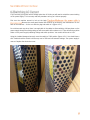
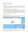
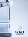
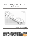
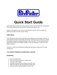
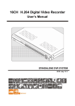
Series 1 User Manual Type A Machines Type A Machines Inc. ©2013 Type A Machines Inc. This document is licenced by Creative Commons Attribution-NonCommercial-ShareAlike (CC BY-NC-SA) Users are free to remix, tweak, and build upon this work for noncommercial use, as long as users credit Type A Machines Inc. and license their new creations under the identical terms. Every effort has been made to ensure that the information contained in this manual is accurate. Type A Machines is not responsible for printing or clerical errors. Type A Machines 926 Howard St. San Francisco, CA 94103 www.typeamachines.com Products in this manual may be covered by US and International Patents. Type A Machines is a regestered trademark of Type A Machines Inc. Any products names mentioned in this manual are the property of their respective parties. V1.05 Congratulations on joining the 3D printing community! You are now the proud owner of the fast, accurate, totally awesome, best in class Series 1 3D printer! Your Series 1 has been 100% manufactured, assembled, and quality tested by the Type A team at our San Francisco, California workshop. Those of us at Type A Machines have a range of reasons for being in the 3D printing industry, but what keeps us coming in every day is the awesome stuff you make. In this guide you’ll find all the resources you need to be up and printing in no time. Our users are doing some pretty amazing things with their Series 1, from robots to architecture, to cookie cutters to cannons! As the newest member of the Type A Machines community, we welcome your input and can’t wait to see what you build. Join us at Forum.TypeAMachines.com and show us your stuff. We think you’re awesome, and we love what you do! 1. What’s in the Box? ...................................... 1 6.3.4. Slice!............................................ 17 2. 3D Printing with Fused Filament Fabrication .. 2 7. Run A Print ............................................... 18 3. WELCOME TO YOUR SERIES 1 ..................... 3 7.1. Connect Series 1 Via Pronterface ......... 18 3.1. Winchester Tool Head/Extruder ............. 4 7.1.1. Set Baud Rate .............................. 18 3.2. Motion System ...................................... 5 7.1.2. Set Com Port ................................ 19 3.3. Electronics ............................................ 6 7.1.3. Connect to your Series 1 ............... 19 4. GETTING STARTED ..................................... 7 7.2. Load a GCode File ............................... 20 4.1. Unpacking and Initial Setup ................... 7 7.3. Print an Object! .................................. 21 4.2. Switching AC Current ............................ 8 7.4. Removing A Printed Object from the Print Surface ..................................................... 22 4.3. Power On ............................................. 9 4.4. USB Connection .................................... 9 4.5. Install the Build Plate ............................ 9 4.6. Loading Filament ................................ 10 7.5. Prepare for Your Next Print .................. 22 7.5.1. Clean the Build Surface ................. 22 8. PERIODIC MAINTENANCE.......................... 23 5. SOFTWARE SETUP .................................... 11 8.1. Replace the Build Surface .................... 23 5.1. Mac Users .......................................... 11 8.1.1. Prepare the Build Plate with pre-cut blue squares: ......................................... 23 5.1.1. Pronterface Printer Control Software ................................................ 11 5.1.2. KISSlicer ...................................... 11 5.2. Windows Users ................................... 12 5.2.1. Drivers ......................................... 12 5.2.2. Pronterface Printer Control Software ................................................ 12 5.2.3. KISSlicer ...................................... 12 6. BASIC OPERATION .................................... 13 6.1. .STL ................................................... 13 6.2. What file types can the Series 1 Read? . 13 6.3. Slice in KISSlicer ................................. 13 6.3.1. Printing Resolution/Speed ............. 15 6.3.2. Infill ............................................. 15 6.3.3. Load your .STL file ........................ 16 8.1.2. Prepare the Build Plate with blue (painter’s) tape: ..................................... 23 8.2. Clean Out a Filament Jam .................... 23 8.3. Tension Belts ...................................... 25 8.4. Tighten Screws ................................... 25 8.5. Clean/Lube Shafts ............................... 25 9. TROUBLESHOOTING ................................. 26 9.1. Z-Height Calibration ............................ 27 9.2. Calibrate the Build Plate ...................... 29 9.3. Replace the Hot End ........................... 30 10. SERIES 1 SUPPORT ................................. 30 10.1. Forum.TypeAMachines.com ............... 30 10.2. Support Request ............................... 30 11. 2013 SERIES 1 SPECS ............................. 31 User Manual Quickstart Guide 3D Printed Object Sample PLA Power Cable Acrylic Build Plate, taped and ready to go! Filament Management System Upkeep Kit containing: 7 MM wrench 2.5 MM Hex Key 2 MM Hex Key 1.5 MM Hex Key Insulated (Ceramic) Screwdriver Heading 1.0. 1 The Type A Machines Series 1 prints a 3D object by placing thin layers of plastic on top of each other until a finished object is built out of the layered plastic. To begin a 3D print, plastic is delivered to the Series 1 Tool Head in the form of “filament” (a long thin strand of plastic, wound onto a spool). The Series 1 then heats the filament to its melting point and pushes, or “extrudes,” the melted filament through the Extruder Nozzle. The Series 1 then moves the Nozzle in a pattern while extruding plastic to draw a very thin cross section of the object that it is printing. The Tool Head fan cools the newly extruded plastic, solidifying it almost instantly. After each layer is completed, the printer moves the Build Surface down a tiny distance, and then extrudes the next cross section of melted plastic on top of the cooled layer below. This method of 3D printing is called Fused Filament Fabrication, or “FFF”. Figure 2.0. 1 The Type A Machines Series 1 was developed in San Francisco, California, to be a bigger, better, and more reliable desktop 3D printer. It features best in class build volume, an innovative modular Hot End replacement system, the ‘Winchester’ quick release for fast filament loading, fingertip Build Plate calibration, and high precision stepper motor s to for ease of use and high resolution printing. Figure 3.0. 1 The Type A Series 1 3D printer features the proprietary Winchester tool Head. It is unique in the 3D printing industry. Precision designed and fabricated in the Type A Machines offices and TechShop in San Francisco, the Winchester Tool Head is designed to allow quick release and loading of both filament and the open source, industry standard “groove mount” Hot End. It has proven incredibly reliable and easy to service. With this advancement, the Series 1 is capable of reliably extruding filament up to 230° C, and running for days on end. Figure 3.1. 1 The Type A Series 1 3D Printer is a Cartesian motion based printer system. This means it can move in 3 linear directions: the X, Y, and Z axes. It does this using precise stepper motors to drive the machine. The X and Y axes control the motion of the Tool Head. X axis moves the tool head left and right, and Y axis moves the Gantry forward and back. Both of these movements are made using high precision timing belts, shafts, and motors. The Z axis moves the Build Surface up and down using a lead screw, shafts, and a stepper motor. The design of the Series 1 maximizes the machine area devoted to the buildable space. This results in a minimal machine footprint with a HUGE build volume. The maximum size of object that can be built is 260mm along the X axis, 230mm along the Y axis, and 230mm along the Z axis (10”x9”x9”). The Series 1 can produce parts with functional tolerances of 0.1 And is capable of a vertical layer height of 0.05 mm. The speeds at which the printer can move along each of these axes are among the fastest in the industry. Figure 3.1. 1 The Type A Series 1 features an all Open Source electronics system. It consists of an Arduino Mega, RAMPS, and Pololu driver chips. The Arduino is the ‘brain’ of the printer. It interfaces with your computer to load control instructions onto the printer and drive it. The RAMPS (RepRap Arduino Mega Pololu) shield serves as the motor control and power distribution system for the Arduino. It helps transfer power and command code from the Arduino to the motor drivers. The RAMPS also serves as the connection point for most of the wiring in the machine. This is where the sensors and heaters in the Tool Head and the fans connect. The last section of electronics is the motor drivers. There are 4 motor drivers per machine, one each to drive the X,Y,Z and Extruder motors. These little chips take instructions from the Arduino and power from the RAMPS to directly control the motors. They send hundreds of commands per second! The electronics compartment is cooled by a fan to keep things from overheating. Figure 3.3. 1 Time to get started! If you haven’t already, now is the time to see what your printer looks like out of the box. Carefully remove the printer from the carton. If the printer is difficult to remove, cut open the edges of the box. Attempting to force the printer out of the box may break it. Remove the packing material from around the printer. The Gantry and Tool Head have been tied down to protect it in transit. Remove the strapping and interior packaging insert between the Gantry and back of panel of the machine. The Gantry and Tool Head should now move freely. Check your package contents to confirm that your Series 1 shipped with all contents. Your Type A Machines Series 1 is Factory configured to use US Standard 110 Volts AC. If you are in the United States, you’re ready to go! If you are using your printer outside of the United State you MAY need to switch your power supply voltage setting. If you do not know your local voltage, review the following article to determine whether you need to switch your voltage: https://en.wikipedia.org/wiki/Mains_electricity_by_country Figure 4.1. 1 If you are using your printer with a Voltage other than 110 Volts you will need to switch the current setting on the power supply. This is an easy and safe procedure as long as it is done properly. First turn the machine around to look at the back. Remove the small panel Marked PSU ACCESS by unscrewing the thumbscrews on the back of the machines – it’s the one with the plug and switch in it (figure 4.2.1). Do not disconnect any wires, there is enough slack in the cables to allow switching. Mid way down on the power supply through the metal grating you will see a switch with numbers on it. There will also be a yellow sticker on the power supply indicating voltage and switch positions. Your switch will be set to 115V. Using the included hexagonal wrench, move the switch to 230V position (figure 4.2.1). You should hear a click. Double check the switch is all the way over to 230V and not between settings. Your power supply is now set. Replace the electronics cover. Figure 4.2. 2 Figure 4.2. 1 Now that your voltage is confirmed it’s time to bring the printer to life. Plug the included Power Cable into the power port on the back panel of the machine. Plug the wall end of the cable into an available socket. Flip the switch on. When the printer is first turned on you should see a small green light turn on in the right power supply bay behind the acrylic arrow window. The electronics bay behind the right arrow window should light up blue. Congratulations! You’re one step closer to printing! Mac and Linux users may now plug the USB cable into their computer. Windows users should follow the procedure set out in section 5.2.1 BEFORE connecting the USB cable. Remember that you’ll need to install the printer control software to operate your Series 1. Your Build Plate comes prepared with a blue square adhered to the printable area. This blue square is your Print Surface, for you to print directly onto. The Print Surface can be marred by oils on your fingertips, so avoid touching the blue surface unnecessarily. To install your Build Plate, rotate it so that the words “Type A Machines Series 1” are oriented right side up toward you. Slot the four holes on the outside corners of the Build Surface onto the four Platform Calibration Bolts on 1 Build Platform. Press down gently to depress the springs on the standoff, then slide the Build Plate away from you to lock it into place. Your Build Surface is now correctly in place. Figure 4.5. 1 Open the Winchester spring lever by resting your thumb on the left edge of Tool Head and using your index finger to pinch the spring lever open. The top of the lever will swing left. With the lever in the open position, you will notice a small hole in the upper surface of the Winchester Clamp Plates, in between the lever and the pinch-wheel. This small hole is the filament loading aperture. Fully insert the free end of your PLA into the aperture and gently release the spring lever. The PLA should now be pinched in between the pinchwheel and the spring lever and fully inserted into the Filament Aperture. Please be aware that the quality of PLA can vary substantially. High quality filament is available through the Type A Machines online store, and for sale by other reputable 3D printing shops. Look for positive user reviews before buying PLA from unfamiliar sources. Figure 4.6. 1 To get your Series 1 ready and printing, you’ll first need to install the software toolchain. This consists of drivers, a slicing engine, configuration files, and control software. We have precompiled installation packages that are available for download on our website. Download the correct files for you operating system. Once your download is completed, Unzip the Mac Setup Package to an appropriate location. You will need to be able to locate the unzipped files later. In the unzipped folder your will see a file called 01_Mac_Pronterface. The Pronterface Application is ready to go with no install required. You can add a shortcut to Pronterface to your dock for easy access. In the folder that you unzipped you will see a folder called 02_KISSlicer. This folder contains the KISSlicer application and configuration files to slice your files. Type A Machines has developed and optimized these settings for your best possible printing. You can add a KiSSlicer shortcut to your dock for easy access. Congratulations! Your software is now setup and you’re ready to slice and print! Download the installation package for your operating system. Select either Windows 32 or 64 bit. Once your download is completed, Unzip the installer package to an appropriate location. You will need to be able to locate the unzipped files later. To be able to use your Series1, your computer must have an Arduino driver installed as well as a version of Python installed. Some users may already have one or both of these installed on their Windows computer. Follow the instructions below to determine whether you need to install one or both of these. As of July 2013 In order for the Arduino driver to install properly, you will have to set Windows to permit installation of unsigned drivers. For tips on how to do this, please visit the Forum.TypeAMachines.com. The first folder you will see is the 00_driver folder. Open it and Install our Arduino driver. Follow the onscreen instructions to install the Arduino driver. Plug the USB cable into a USB port on your computer. Your computer should display a message that says that an Arduino device has now been connected. The message may also show a COM number. This is the port the printer will use to communicate with the computer. Before installing the print control software you need to have Python installed. The majority of PC’s out there already have this but if you don’t or aren’t sure we have included an installer in the download package. Alternativly you can go to http://www.python.org/getit/. In the unzipped file your will see a folder called 01_Pronterface. The Pronterface Application is ready to go with no install required. You can right click pronterface.exe and create a shortcut on your desktop for easy access later. In the folder that you unzipped you will see a folder called 02_KISSlicer. This folder contains the KISSlicer application and configuration files to slice your files. Type A Machines has developed and optimized these settings for your best possible printing. You can add a KiSSlicer shortcut to your desktop for easy access. Congratulations! Your software is now setup and you’re ready to slice and print! 6.1. The first step in the process from 3D Model to 3D Print is to export your 3D model from your modeling program as a .STL file. STL is an industry standard for 3D printing files. Your model must be a closed, ‘water-tight’ mesh. This is critical to producing a quality print. There are many software modeling tools and Mesh Repair utilities you can use for this. The Series 1 reads instructions about how to move the extruder and build platform, and when to extrude filament, from a file called a GCode file. GCode is produced by ‘slicing’ software. GCode files can end “.gcode” or “.gco.” GCode files must be made with settings specific to the printer that you want to print the file on. The Setup Package file that you downloaded includes a few GCode files for you to get printing right out of the gate. If you’d like to print one of these files, then you’re ready to go. If you’d like to create your own GCode file, then you’re going to need to slice it first. Figure 6.3. 1 Launch KISSlicer. The first time you open KISSlicer it will not have the visualization of our print bed loaded. To visualize the Series 1 click the ‘Printer’ tab in the settings box (figure 6.3.1). Then in the bottom right corner of the settings box click the box marked ‘…’. Figure 6.3. 2 Open the file location where you unzipped the Type A Machines Setup Package. The Setup Package includes a model of the Print bed for your reference. Open the file called “platform (figure 6.3.2). Figure 6.3. 3 KISSlicer now shows a visualization of the Series 1 Build Platform (figure 6.3.3). Figure 6.3. 4 Under settings, select the tab marked ‘Style. This tab allows you to control the resolution, and thus the speed of your print (figure 6.3.4). There are a range of settings from ‘Draft’ through Super-Fine. At Type A, we usually use Fine setting. It’s a balance between speed and resolution and it’s a great place to start. Figure 6.3. 5 From the ‘Style’ tab, you will see the Infill slider control at the bottom of the settings are. This controls the amount of plastic filling that will support the inside of your 3D printed object. You can toggle the infill from solid, which prints VERY slowly, but results in very strong prints, to to 2.5% infill, which prints more quickly but has a lower finished strength (figure 6.3.5). Figure 6.3. 6 To load a .STL file, click ‘OPEN’ and then navigate to the desired STL file. To use one of the supplied Type A Machines .STL files, open the file where you unzipped the Setup Package and open the folder called Test Prints” select one of the included .STL files (figure 6.3.6). Figure 6.3. 7 Figure 6.3.7 shows a visualization of a loaded .STL file. If the file you loaded looks very small you may be having a unit conversion problem. To fix this, right click on the image of the .STL in the upper right hand corner (figure 6.3.7) and click “inch->mm”. This will scale your model correctly. Figure 6.3. 8 When you are satisfied with your settings click “Slice” in the upper right hand corner to slice your .STl (figure6.3.8). The visualization will turn green when slicing is completed. Figure 6.3. 9 Click the ‘Models+Paths’ button above the visualization to switch views. This is now a visualization of your GCode. You can now use the slider on the right of the visualization to slide your slice through the model. If you are satisfied that your model sliced correctly, click ‘Save’ at the upper right hand corner of the screen and select a location to save your GCode for printing. Now it’s time to get that printer moving. Confirm that the USB Cable is connected to your computer. Launch the Pronterface application. 7.1.1. Figure 7.1. 1 Before beginning your first print, you will need to set the Baud rate for the connection. Confirm that your Series 1 is connected via USB to your computer, then highlight the field left of ‘Connect’ and type in ‘230400’ (figure 7.1.1). Pronterface will remember this for future connections. Figure 7.1. 2 Pronterface should automatically detect the correct COM port and display it to the right of the box called “Port” (figure 7.1.2). If you have multiple printers or other devices connected, you may need to manually specify the COM port by clicking the drop down menu and selecting the correct one. Figure 7.1. 3 Click ‘Connect.’ The lights on the printer will flash and a ‘Connecting…’ message will appear in the right hand dialog box (figure 7.1.3). If the window does not look like the one above, double check the Baud rate is 230400, then try selecting another port. Figure 7.2. 1 To load one of the supplied GCode files, click the “Load” button. Open the file where you unzipped the Setup Package, then open the Test_Models folder. Select any of the premade GCODE files. If you have another GCode file that you want to print, select it and open it. Figure 7.2. 2 After the file is loaded you will see a visualization of it appear in the window as well as some information appear on the right hand command bar. It will give you the bounds as well as the estimated print duration. We have found this estimate to be initially 5-15% slower than the actual print time. Now it’s time for the magic to start! Take a deep breath, make sure the filament is able to feed freely, and click print. When you do this a several things will happen: 1) your printer will move all three axes to ‘home’, ’2) It will then move to the front-center of the build surface and pre-heat. You can watch it’s progress in Pronterface. Click the ‘monitor printer’ box to see detailed reports. 3) When the printer reaches temp, it will extrude a small amount of filament material. You can manually wipe this away with tweezers, or it will wipe away on the build surface. 4) The fan should turn on; this helps solidify the printed part. 5) The head will move to begin extruding your print. Figure 7.3. 1 It’s a good idea to watch your first layer complete before walking away. This is the most critical part of the print and chances are if your first layer is good the rest will be too. The extrusion should spread onto the print surface and strongly adhere to it. It should not be stringy nor should it be crushed into the surface. Your printer is calibrated for correct initial extrusion height during quality control, and should not need adjustment out of the box. If you have a problem with extrusion adhesion refer to section 9. You have just started your first 3D print with The Type A Machines Series 1. Time to kick back, relax, and start designing your next 3D object! When your print completes, the gantry and head will move away to the back of the machine. Many times depending on your object, you will be able to pop it off the blue print surface by gently prying. If your finished part does not come off easily you can quickly and easily remove the build plate for easier access. This is particularly useful for prints with a large footprint. To remove the build plate, wrap your hands. With your thumbs on top of the surface press down gently to depress the Calibration Bolt springs. Now slide the surface towards you to detach it from its bolts (figure 7.4.1). Figure 7.4. 1 Once you have removed the Build Plate from the machine, try to get a corner. You can then use a putty or butter knife carefully pry the rest of the part off. If your part is really stuck you can brace the build surface against the edge of a sturdy desk or counter and gently apply pressure to the outer edges to cause the build surface to flex slightly. Flexing the build surface gently should make one or more edges of your printed object come loose from the print surface. Once your print is loose, you should be able to pull the rest of it off of the surface. You will be able to print multiple times before your Print Surface will need to be replaced. In order to promote good adhesion of the initial print layer, avoid touching the blue Print Surface with your fingers so as not to transfer oils on the Print Surface. Your Print Surface can be cleaned for repeated use with “Simple Green” cleaner. Alcohol based cleaners should not be used as they will cause weakening and eventual disintegration of the acrylic Build Plate. You machine is designed to require very little upkeep and maintenance. In some instances, the Series 1 has run 24 hours a day for months without needing to service. But depending on the environment that the Series 1 is kept in, and the type of use, you may need to do some basic maintenance from time to time. After multiple prints, you may notice that small pieces of the blue Print Surface have begun to tatter and come off on your printed object. This indicates that it’s time to replace your Print Surface. Your print surface can be replaced using cut to size blue squares from Typeamachines.com, or by using 2 inch wide blue painter’s tape. For general use the Type A Machines pre-cut blue squares work well. They provide a mediumhigh amount of adhesion and are available in the Type A Machines web store. For more delicate prints and easier removal, 3M 2093-EL tape provides a low-medium amount of adhesion. To prepare the Build Plate with pre-cut blue squares, carefully peel one edge of the square and fold it down about an inch from the edge of the square. Align the exposed edge to the recessed print area guide on the Build Plate and use a credit card or small squeegee to adhere it while squeezing out any bubbles. Grasp the backing paper that was folded back, and pull it toward you. Expose the adhesive back of the blue square gradually while using a credit card or squeegee to express any bubbles or voids. Your Print Surface is now prepared. To prepare the Build Plate with blue tape, peel a length of tape about eleven inches long, align it with the recessed guide at the bottom of the Build Plate and adhere it so that a small edge extends over the outside of the guide to the left and right. Peel a second portion of tape eleven inches long, and abut the edge to the edge already placed on the Build Plate. For a clean first extrusion layer, do not overlap the tape. Repeat this process until the entire recessed square guide area is covered with tape. Use a razor or breakaway knife by running it down the recessed guide to trim away any excess tape. Your tape Print Surface should now be solidly adhered to the Build Plate without any bubbles or voids. Your print surface is now prepared. In the course of normal operation your Hot End may become clogged. This can happen from dust on your filament, changes in humidity, or a variety of other factors. Luckily these clogs are generally easy to clear. Review section 9.3 to learn how to remove the front clamp, and keep a 2.5mm hex key at hand. Do not disassemble the front clamp yet. Blow off any filament powder that may have accumulated due to the jam. You may also clean it with a small wire brush or a can of compressed air. Power on your Series 1, and connect via USB to your computer. Launch Pronterface. Manually set the temperature in Pronterface to 185° C, and make sure the fan is on. When the Hot End reaches 185° C, remove any filament from the filament Aperture (figure 8.4.1). Take a length of .013” music wire (or a high E guitar string) and thread it up through Extruder Nozzle. The music wire should come out through the Filament Aperture with a small bead of plastic on it. Immediately pull the wire up through and out of the Tool Head. Do this twice. If the music wire does not come through the aperture use the 2.5 mm hex key to remove the front clamp from the Tool Head as described in section 9.3. Continue to thread the music wire through the loosened Hot End. The music wire will now pass through the Hot End. After threading the music wire through once, thread the music wire through again. You can now reassemble the front clamp. Insert high quality filament end into the Filament Aperture. Manually push the filament into the aperture. You should be able to see it come out of the Extruder Nozzle with steady, but not excessive force. If you are unable to get filament to come out manually, repeat the unclogging procedure. Now that the filament jam is cleared, make sure your hands are outside the machine and in Pronterface click “extrude” to push some plastic through using the Winchester. Melted filament should come out through the Extruder Nozzle. If it does not or you hear the motor skipping or making noise, repeat the unclog procedure. If after 3 attempts the Hot End is still fouled you may need a replacement. Hot Ends can be purchased through the Type A Machines store. Figure 8.2. 1 Figure 8.2. 2 Figure 8.2. 3 For optimal accuracy your belts should remain tight. You can test their tightness with a finger, it should spring back with almost a guitar string tension. You will need the included 7mm wrench and 2.5mm Hex Key. First use the 7mm wrench and 2.5mm Hex Key to loosen the Y or X Tension Adjust Bolt. Tension the belt by pulling on the adjustment bolt with the wrench, then tighten the bolt with the hex key. In rare cases due to vibration of the machine screws can come loose over time, the critical components all have locking nuts to prevent this. Screws can loosen in very dry environments or when the machine has been moved many times. In your included toolkit there is a 2mm wrench that is the perfect size for tightening most of the bolts on the machine. In very rare cases the Hot End mounting clamps can come loose. This will be apparent by the Hot End wobbling when touched or while printing. To fix this turn the machine off and allow the head time to cool down. Remove the front clamp over the Hot End by following procedure in section 9.3. Use the 2.5mm hex key, tighten the now exposed bolts. And re-install the Front Clamp This should alleviate any wobble in the clamp. In dusty environments the Shafts have a tendency to pick up dust and floating particulates. After a great deal of use this can eventually cause motion problems and may damage the bearings. Clean the Shafts with an alcohol dipped clean rag, microfiber cloth, or paper towel. After any accumulated matter has been removed re-lubricate the Shafts using either 3-in-1 Oil or Tri-Flow. With the Series 1 turned off, squirt oil onto the Shafts where they meet the bearings. Move the gantry and Tool Head back and forth to work the oil into the Shafts and bearings. This procedure will reduce running noise as well. No Extrusion Layer of Print on First Build Surface too close to Extruder Nozzle reset Z height. See Section 9.1 Build surface too high or too low reset Z height. See Section 9.1 Improper print surface material Print directly onto blue print surface. Improper build platform calibration recalibrate Build Plate. See Section 9.2 Hot End clog de-clog Hot End (page). See Section 8.2 filament tangle clean extruder, reload filament Hot End connector unplugged plug in connector unable to reach temp Restart Pronterface. Power machine off and on. dirty Shafts lubricate Shafts. See Section 8.5 belt tension adjust belt tension. See Section 8.3 improper print surface material Replace print surface with appropriate. See Section 8.1 Accidental print directly onto acrylic build surface Replace acrylic build surface No lights machine unplugged plug in machine, flip switch. See Section 4 Pronterface shows no Com Ports USB Cable disconnected Connect USB cable. See Section 4.4 Arduino driver not installed See Section 5.2.1 Configuration files not in same folder as KISSslicer Mac user, see Section 5.1.2. Windows user see Section 5.2.3 Poor PLA Adhesion to Build Surface No/Poor Extrusion No/Loud Motion Object will not detach from build surface KISSlicer can’t find configuration files The Series 1 features an easily accessible black knob at the back of the build platform which can be adjusted to increase or decrease the height for the first layer of printing. The knob is set to the correct height during quality control, but it may require some refinement due to normal use or movement f(figure 9.1.1). Figure 9.1. 1 The Z height adjustment knob works by triggering a micro-switch under the upper back plate of the Series 1. It should be adjusted to trigger the switch when the Build Surface is just below the tip of the Extruder Nozzle. Figure 9.1. 2 To test the Z height, use a piece of paper. Launch Pronterface. With the Hot End cooled off and the Extruder Nozzle clean of PLA, connect to the printer and click the green Z Home button (figure 9.1.2). When the platform stops moving upward it has reached the Home position. You should be able to slide a piece of paper easily under the tip of the Hot End between the Extruder Nozzle and Build Surface. There should be some resistance but the paper should move freely. If the gap is too small to slide a sheet of paper between the nozzle and the Print Surface, the Z height is too high. Alternatively if the sheet of paper can be slid under the nozzle with no resistance, your Z height is too low. Click +Z 10 button in Pronterface a few times to move the platform down so you can adjust the set screw Figure 9.1. 3 (figure 9.1.3). At the top of the build platform structure there is a graphic that shows which direction to turn the screw for the desired adjustment (figure 9.1.4). It is best to go in ½ turn increments at first. Then either Full turn or ¼ turns each adjustment depending on how far you are trying to adjust it. Figure 9.1. 4 If the Extruder Nozzle is too close: Move the platform away from the Hot End and increase the gap by turning the screw to the left (counter-clockwise). If the Extruder Nozzle is too far: Move the platform closer to the Hot End and decrease the gap by turning the screw to the right (clockwise). After each adjustment to the screw click Z Home in Pronterface and repeat the paper test procedure. Your build plate is calibrated before it leaves the Type A Machines Factory to print the initial layer of an object at an even height. The Build Plate Calibration Bolts feature two finger nuts. A bolt passes through the Build platform, with one nut above and one below. These nuts work together to adjust the height of the Build Plate and then to lock the adjustment in. If you are experiencing problems with first layer adhesion when a portion of the first layer is properly adhered and another portion is not, first replace the blue tape print surface and try again. If problems persist you MAY need to re-calibrate your build plate. To adjust one corner of the Build Plate higher, gently loosen the lower nut and tighten the upper nut, then tighten the lower nut to lock the adjustment in. To adjust one corner of the Build Plate lower, gently loosen the upper nut, and then tighten the lower nut to lock it in. Clear the build plate of any prints or other materials. Launch Pronterface, move the build platform down. Place the included 7mm wrench on the build plate in the front right corner (figure 9.2.1). Use the open head of the wrench as a milled standoff block. In Pronterface, move the tool head to be directly over the wrench. Move the Platform so it is almost touching the wrench (figure 9.2.2). Now adjust the two finger nuts until the wrench comes in light contact with the Extruder Nozzle. You should be able to move the wrench around under the head while feeling light resistance from the contact. Remember to tighten the lower nut to lock the adjustment in (figure 9.2.3). Manually move the Tool Head each of the four corners, place the wrench beneath the Extruder Nozzle and repeat knurled nut adjustment procedure. You build plate should now be Calibrated. Confirm this my moving the wrench and head to the front right. You may need to tweek this bolt since you have adjusted the others. Figure 9.2. 1 Figure 9.2. 2 Figure 9.2. 3 To replace a Hot End first turn off the machine and disconnect from your computer. Make sure the Hot End is cool. Unscrew the Hot End Clamp access bolt using the 2.5mm Hex Key. After the front of the clamp is off use the hex key to pop the Hot End out of the groove mount slot. Disconnect the Thermister and Heater Wires (the purple-clear and orange-green wires). Take great care to disconnect them gently. Only apply pressure on the black connector bits themselves. The connectors are easily damaged. Set the used Hot End aside. Slide the new Hot End into the mount with the wires facing left. Reconnect the connectors Figure 9.3. 1 carefully. Screw the front clamp back on. You have just installed a new Hot End! If you’re having trouble getting a print to run smoothly, and you haven’t been able to find a fix in this manual, the next place to look is Forum.TypeAMachines.com. The Type A Machines Forum is privileged to have an active, well informed, and helpful user group. The Forum is also one of our favorite places to announce product giveaways, betas, and competitions. And it’s a great place for you to show off your awesome prints! To initiate a support request, please e-mail [email protected], or visit support.typeamachines.com. Width: 17.66” (448.56mm) Weight: 16lbs (7.25kg) Height: 18.36” (466.34mm) Operating Baud Rate: 203400 Depth: 16.14” (409.95mm) Operating Voltage: 100-120, 200-240VAC Build Area X: 10.1” (260mm) Internal Voltage: 12 VDC Build Area Y: 9.05” (230mm) Operating Temperature: 50-105°F (10-41°C) Build Area Z: 9.45” (240mm) Max Extruder Temp: 230°C Build volume: 729ci (14.35 liters) ° CENTIGRADE