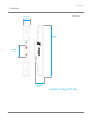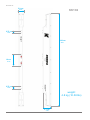
1
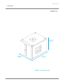
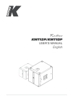
Kobra
KK52/KK102
USER’S MANUAL
English
KK52/KK102
Contents
SYMBOLS 5
1. INTRODUCTION
7
2. APPLICATIONS 7
3. KEY FEATURES 7
4. UNPACKING 8
5. WARRANTY
8
6. SAFETY
8
7. PHYSICAL
9
8. REAR PANEL
11
9. COVERAGE
12
10. WIRING
14
11. PROTECTION CIRCUITRY
14
12. ACCESSORIES AND CONFIGURATIONS
15
K-Base215
K-Fly2
16
K-Joint2
16
K-Wall2L
17
K-Wall2
17
18
K-KCluster2 / K-PCluster2
K-Foot2
18
19
K-KStage2 / K-PStage2
13. SERVICE 19
14. Specifications20
REV. A
3
KK52/KK102
4
REV. A
KK52/KK102
SYMBOLS
K-array declares that this device is in compliance with applicable CE standards and
regulations. Before putting the device into operation, please observe the respective
country-specific regulations!
WEEE
Please dispose of this product at the end of its operational lifetime by bringing it to your local
collection point or recycling center for such equipment.
This symbol, wherever it appears, alerts you to important operating and maintenance
instructions in the accompanying literature. Read the manual!
Warning! Dangerous voltages: RISK of electric shock.
This symbol alerts the user to the presence of recommendations about the product’s use
and maintenance.
This device complies with Restriction of Hazardous Substances Directive.
REV. A
5
KK52/KK102
6
REV. A
KK52/KK102
1. INTRODUCTION
The K-array Kobras are passive speaker systems, comprised of 2” neodymium magnet transducers housed
in an elegant and sturdy stainless steel chassis. Available in two lengths, the KK52 features 8 drivers in a 0.5
m (19.7”), while the KK102 features 16 drivers a 1 m (39.4”) chassis. The vertical dispersion pattern can be
switched for wide or narrow coverage, allowing for a great variety of applications. The Kobra’s closely spaced
cone drivers provide phase coherence, low distortion and focused listening both up close and at a distance.
To accommodate a range of applications, the vertical dispersion pattern can be switched for either wide or
narrow coverage. Optional rigging and linking accessories allow multiple speakers to be interconnected,
creating a wide array of vertical and horizontal configurations for temporary or permanent installation.
For integration with other speakers or amplifiers, the KK52 and KK102 offer selectable impedance (16Ω/64Ω
for the KK52 and 8Ω/32Ω for the KK102). Set to 64Ω up to eight KK52s can be powered via a single amplifier
channel, simplifying installation of wider distributed installed systems.
Kobras are able to reproduce the entire vocal frequency range with excellent intelligibility, starting from 150 Hz.
Integrating powered subwoofers from K-array’s Redline series (KMT12, KMT18, KMT21) ensures excellent
coverage of the entire musical frequency range.
K-array’s KA amplifier series also features custom presets, optimized for use with the Kobra series.
All Kobra components are designed by K-array and custom-made under K-array’s quality control system.
2. APPLICATIONS
3. KEY FEATURES
•
•
•
•
•
•
•
•
•
•
Theatres, Club, Churches
Front fill and under-balcony fill
Portable and installed AV systems
Stage and AV studio monitoring
REV. A
Unique performance-to-size ratio
Vertical, Horizontal and 3D line-array applications
Multiple 2” long-excursion full-range cone drivers
Wide horizontal coverage
Electronically protected
Selectable impedance (KK52: 16 / 64 Ω, KK102: 8 / 32 Ω)
• Selectable vertical pattern (Spot / Flood)
• Weather proof, suitable for outdoor installations
• Available in black or white
7
KK52/KK102
4. UNPACKING
Each K-array loudspeaker is built to the highest standard and thoroughly inspected before leaving the factory. Upon arrival,
carefully inspect the shipping carton, then examine and test your new loudspeaker. If you find any damage, immediately
notify the shipping company. Only the consignee may institute a claim procedure regarding the system’s electronic equipment.
5. WARRANTY
K-array systems are warranted against manufacturing defects in materials or craftsmanship over a period of 2
years from the date of original purchase. During the warranty period K-array will, at its discretion, either repair or
replace products which prove to be defective provided that the product is returned in its original packaging, shipping
prepaid, to an authorized K-array service agent or distributor. K-array cannot be held responsible for defects caused
by unauthorized modifications, improper use, negligence, exposure to inclement weather conditions, acts of God
or accidents, or any use of this product that is not in accordance with the instructions provided by K-array. K-array
is not liable for consequential damages. This warranty is exclusive and no other warranty is expressed or implied.
This warranty does not affect your statutory rights.
6. SAFETY
WARNING
• Only install the speaker in a location that can
structurally support the weight of the unit. Doing
otherwise may result in the unit falling down and
causing personal injury and property damage.
• Professional loudspeakers are capable of
producing extremely high sound levels and should
be used with care. Hearing loss is cumulative and
can result from extended exposure to levels in
excess of 90dB.
• Do not operate the speaker for an extended period
of time with the sound distorting.This is an indication
of malfunction, which can cause heat build-up and
result in a fire.
8
• Never stand close to loudspeakers driven at high level.
• Suspending the system should only be done by
qualified personnel, following safe rigging practices.
Secure fixings to the building structure are vital.
If there is any doubt, seek professional help from
architects, structural engineers or other specialists.
• No open flame sources, such as lighted candles,
should be placed near the device.
• Do not attempt to disassemble the unit. The unit
contains no user serviceable parts. Repairs should
be performed only by factory trained service
personnel.
REV. A
KK52/KK102
7. PHYSICAL
KK52
5.9 cm
2.32”
50 cm
19.7”
12 cm
4.72”
8.1 cm
3.19”
weight: 2.3 kg (5.07 lbs)
REV. A
9
KK52/KK102
5.9 cm
KK102
2.32”
2.75 cm
1.08”
100 cm
39.4”
12 cm
4.72”
2.75 cm
1.08”
weight:
4.8 kg (10.58 lbs)
8.1 cm
3.19”
10
REV. A
KK52/KK102
8. REAR PANEL
1
2
3
1
1) Mounting screw holes. Most K-array mounting or flying accessories are designed to screw into the speakers
using these holes. The KK52 is equipped with two screw holes, while the KK102 is equipped with four.
2) Impedance switch. Selects the impedance of the speaker. Impedance must be set to high (64 Ω for KK52 and
32 Ω for KK102) when speakers are driven by KMT active modules. Low impedance may be used when speakers are
driven by most KA series amplifiers (KA3, KA7, KA10). Please refer to your amplifier’s specifications to select the
correct speaker impedance for your configuration.
3) Coverage switch. Selects the vertical dispersion of the speaker. Flood coverage sets a wide vertical
diffusion angle of 60° (KK52) / 35° (KK102). Flood coverage is suggested for single speakers in diffused (image 1)
short throw applications, to obtain maximum diffusion with a minimum footprint. Spot coverage sets a narrower
vertical diffusion angle of 10° (KK52) / 7° (KK102). Spot coverage is recommended for long throw or monitoring
applications (image 2). In most multi-speaker applications, set coverage to Spot (image 3). A combination of Flood
and Spot may also be effective for downfill applications (image 4).
REV. A
11
KK52/KK102
9. COVERAGE
Img1: Flood coverage
Img2: Spot coverage
12
REV. A
KK52/KK102
Img3: Array - spot coverage
Img4: Array - Downfill application
REV. A
13
KK52/KK102
10. WIRING
Kobra KK52 and KK102 internal wiring is designed to pick up audio power signal from pins 1+ / 1- of a NL4
connector. 2+ and 2- pins, such as 1+ and 1-, are directly wired from one socket to the other, so signal can
pass through multiple KK modules without additional external cabling.
11. PROTECTION CIRCUITRY
Speakers are electrically protected from brief power overloads, within a reasonable range. Overloading the
speaker for extended periods of time can cause damage, so proper system design is strongly advised.
14
REV. A
KK52/KK102
12. ACCESSORIES AND CONFIGURATIONS
K-array offers a variety of dedicated accessories to mount and interconnect KK (Kobra) and KP (Python) series
speakers for a wide array of possible configurations.
K-Base2
Standing accessory for KK/KP speakers. For proper installation and operation, use with K-Foot2 and K-Joint2.
TIPS: where possible, screw the feet of K-Base2 to the ground.
K-Foot2
K-Joint2
WARNING
Before connecting KK/KP series speakers to a K-Base 2, check the stability of the
ground where K-Base 2 is to be placed.
K-Base 2 should not be placed in a zone accessible to the audience.
Take maximum precaution in highly windy locations, especially when screwing the
K-Base2 to the ground is not possible.
REV. A
15
KK52/KK102
K-Fly2
Flying accessory set for KK/KP speakers.
For proper installation and operation, use with K-Joint2.
K-Joint2
WARNING
Consult the dedicated product manual for
safety information and operation details.
K-Joint2
Attachable joint to link a KK/KP speaker to most accessories
or to another KK/KP speaker with continuously variable
angle (-10° <. . . . > 10°).
16
REV. A
KK52/KK102
K-Wall2L
Wall / stand mounting accessory for KK/KP speakers with bi-dimensional tilting features.
K-Wall2L is designed to be screwed directly to the mounting screw holes of KK/KP speakers. When used with
KK102 it can be screwed to the internal or the external screw holes depending on the width of the desired angle.
K-Wall2
Wall mounting accessory for KK/KP speakers with full 3-dimensional tilting features.
K-Wall2 is designed to be screwed directly to the mounting screw holes of KK/KP speakers. When used with
KK102, the K-Wall2 can be screwed to either internal or external screw holes, depending on the width of the
desired angle.
REV. A
17
KK52/KK102
K-KCluster2 / K-PCluster2
Wall mounting accessory for a horizontal cluster of three KK52/102 speakers.
K-KCluster 2 / K-PCluster 2 comes in a set of three different models: one with no angle between the three hanging
speakers, one with a 30° angle between speakers, one with a 60° angle between speakers.
0°
0°
30°
30°
60° 60°
K-Foot2
35 mm pole mounting accessory.
A 35 mm threaded pole is included for connecting additional K-array products such as KMT subwoofers or K-Base2.
18
REV. A
KK52/KK102
K-KStage2 / K-PStage2
Ground laying accessories for KK/KP series speakers.
K-KStage 2 / K-PStage 2 allow users to safely lay KK / KP series speakers on the ground with three different
angles: 0°, 30° and 45°. Ideal applications are monitoring and front-fill.
13. SERVICE
To obtain service:
1) Contact the official K-array distributor in your country. Your local distributor will direct you to the appropriate
service center.
2) If you are calling for service, please have the serial number(s) of the unit(s) available for reference. Ask for Customer Service, and be prepared to describe the problem clearly and completely.
3) If the problem cannot be resolved over the phone, you may be required to send the unit in for service. In this
instance, you will be provided with an RA (Return Authorization) number which should be included on all shipping
documents and correspondence regarding the repair. Shipping charges are the responsibility of the purchaser.
Any attempt to modify or replace components of the device will invalidate your warranty. Service must be performed by an authorized K-array service center.
Cleaning:
Use only a soft, dry cloth to clean the housing. Do not use any solvents, chemicals, or cleaning solutions
containing alcohol, ammonia, or abrasives. Do not use any sprays near the product or allow liquids to spill
into any openings.
REV. A
19
KK52/KK102
14. Specifications
KK52
Acoustics
Speakers power handling
200 W (AES)
Max power
400 W 1
Impedance
16Ω or 64Ω (selectable)
Frequency range
150 Hz - 20 KHz.
SPL 1W / 1mt
95 dB 2
Maximum SPL
118 dB continuous - 124 dB peak
Coverage
Horizontal
Vertical
110°
10°- 60° (selectable)
Crossover
Type
Frequency
External Crossover required
High pass @150 Hz, 24 dB/oct suggested minimum
Transducers
Full range
8 x 2” Neodymium magnet with 0.75” voice coil
Power Audio Input
Connectors
Wiring
2 x 4-pin Speakon
1+ 1- (signal IN & LINK); 2+ 2- (through)
Selection Switch
Vertical pattern
Impedance
Spoot - Flood
16Ω - 64Ω
Physical
Dimensions
Weight
8.1 x 50 x 5.9 cm (3.19” x 19.7” x 2.32”)
2.3 kg (5.07 lbs)
1. Maximum RMS applicable power for a musical signal, the
reference signal is the one proposed by EIAJ standard.
2. Measured @4 mt then scaled @1 mt
New materials and design are introduced into existing
products without previous notice. Present systems may differ
in some respects from those presented in this brochure.
20
REV. A
KK52/KK102
KK102
Acoustics
Speakers power handling
400 W (AES)
Max power
800 W 1
Impedance
8Ω or 32Ω (selectable)
Frequency range
150 Hz - 20 KHz.
SPL 1W / 1mt
98 dB 2
Maximum SPL
124 dB continuous - 130 dB peak
Coverage
Horizontal
Vertical
110°
7°- 35° (selectable)
Crossover
Type
External Crossover required
Frequency
High pass @150 Hz, 24 dB/oct suggested minimum
Full range
16 x 2” Neodymium magnet with 0.75” voice coil
Transducers
Power Audio Input
Connectors
Wiring
2 x 4-pin Speakon
1+ 1- (signal IN & LINK); 2+ 2- (through)
Selection Switch
Vertical pattern
Spoot - Flood
Impedance
8Ω - 32Ω
Dimensions
8.1 x 100 x 5.9 cm (3.19” x 39.4” x 2.32”)
Physical
Weight
4,8 Kg (10.58 lbs)
1. Maximum RMS applicable power for a musical signal, the
reference signal is the one proposed by EIAJ standard.
2. Measured @4 mt then scaled @1 mt
New materials and design are introduced into existing
products without previous notice. Present systems may differ
in some respects from those presented in this brochure.
REV. A
21
KK52/KK102
22
REV. A
KK52/KK102
The contents of this manual are furnished for informational purposes only. Hp Sound Equipment s.r.l. assumes no responsibility
for any errors or inaccuracies that may appear in this manual. Hp Sound Equipment s.r.l. reserves the right to make modifications
without prior notice.
REV. A
23
UMC029AA01ENA
K-array s.r.l. unipersonale
Via Paolina Romagnoli - 50037
San Piero a Sieve (Firenze) - Italy
tel. +39 055 8487222 - fax. +39 0558487238
e-mail: [email protected]
www.k-array.com
KMT12/KMT18
USER’S MANUAL
English
KMT12/KMT18
2
REV. A
KMT12/KMT18
Contents
SYMBOLS 5
1. INTRODUCTION
7
2. APPLICATIONS 7
3. KEY FEATURES 7
4. UNPACKING 8
5. WARRANTY
8
6. SAFETY
8
7. PHYSICAL
9
8. AMPLIFIER
11
8.1 AC POWER CONNECTOR
11
8.2 VOLTAGE REQUIREMENT
11
8.3 CURRENT REQUIREMENT
11
8.4 REAR PANEL
12
8.5 TOUCH SCREEN FUNCTIONS
14
8.6 AUDIO INPUT CONNECTOR WIRING
15
8.7 AMPLIFICATION AND PROTECTION CIRCUITRY
15
9. K-Framework16
9.1 SYSTEM REQUIREMENTS
16
9.2 Installation and set up16
9.3 User Tabs:19
INPUT TAB
ROUTING TAB
DELAY TAB
20
21
21
OUTPUT TAB
22
10. SERVICE 23
11. Specifications24
12. Declaration of conformity REV. A
26
3
KMT12/KMT18
4
REV. A
KMT12/KMT18
SYMBOLS
K-array declares that this device is in compliance with applicable CE standards and
regulations. Before putting the device into operation, please observe the respective
country-specific regulations!
WEEE
Please dispose of this product at the end of its operational lifetime by bringing it to your local
collection point or recycling center for such equipment.
This symbol alerts the user to the presence of recommendations about the product’s use
and maintenance.
Warning! Dangerous voltages: RISK of electric shock.
This symbol alerts the user to the presence of recommendations about product’s use and
maintenance.
This device complies with Restriction of Hazardous Substances Directive.
REV. A
5
KMT12/KMT18
6
REV. A
KMT12/KMT18
1. INTRODUCTION
The K-array KMT12 and KMT18 are full-featured audio systems featuring a powered subwoofer, programmable onboard DSP and multiple analog and digital inputs and outputs for creating a wide array of speaker configurations.
The KMT12 features a 12” subwoofer, while the KMT18 features an 18” subwoofer.
The KMT 12 and KMT 18 feature an integrated touch screen, providing intuitive control over the main DSP
functions: input / output levels, signal routing, offset delays for subwoofer and speakon output (up to 12 ms.,
each) and overall system delay (up to 330 ms.). All DSP functions, including EQ, can also be remote controlled via
software over USB or RS485 (3-pin XLR).
The KMT series provides two balanced analog line level inputs and a two-channel AES/EBU digital input. An
integrated class D amplifier delivers 2 x 1050 W at 8Ω, with a max THD of 1% (EIAJ test @ 1KHz). The KMT12 /
KMT18 feature multiple analog and digital outputs, including a Speakon output to connect a wide array of passive
speakers including mid-high modules (KK52, KK102) or additional passive subwoofers (KMT12P or KMT18P). To
optimize performance, the on-board DSP includes up to 40 programmable presets. The first 8 have been designed
by K-array, the additional 32 slots can be used to create, save, and store personal presets using the K-framework
software.
The KMT series’ unique four-corner port configuration provides symmetrical back loading to the speakers, for
extended bass response with very low distortion. The port configuration also provides incredible structural strength
to the cabinet, despite its light weight. Pocket handles and an M20 thread mount position for attaching mid-high
speakers makes the Redline series convenient to use and ideal for medium throw applications in theaters, concert
halls, and Audio/Video installations.
All KMT components are designed by K-array and custom-made under K-array’s quality control system.
2. APPLICATIONS
3. KEY FEATURES
•
•
•
•
•
•
•
•
•
•
•
Theatrical sound reinforcement
Concert halls, clubs, houses of worship
Portable and installed audio-visual systems
Cinema and special effects
REV. A
Unique performance-to-size ratio
Direct radiating, long excursion driver
Ultra fast set-up and dismantling system
Fitted with integrated handles and castors
Analog and digital AES/EBU inputs
Remote software control over USB and RS485
Optimized for use with KK52 / KK102, KMT12P
/ KMT18P
7
KMT12/KMT18
4. UNPACKING
Each K-array loudspeaker is built to the highest standard and thoroughly inspected before leaving the factory.
Upon arrival, carefully inspect the shipping carton, then examine and test your new loudspeaker. If you find any
damage, immediately notify the shipping company. Only the consignee may institute a claim procedure regarding
the system’s electronic equipment.
5. WARRANTY
K-array systems are warranted against manufacturing defects in materials or craftsmanship over a period of 2
years from the date of original purchase. During the warranty period K-array will, at its discretion, either repair or
replace products which prove to be defective provided that the product is returned in its original packaging, shipping
prepaid, to an authorized K-array service agent or distributor. K-array cannot be held responsible for defects caused
by unauthorized modifications, improper use, negligence, exposure to inclement weather conditions, acts of God
or accidents, or any use of this product that is not in accordance with the instructions provided by K-array. K-array
is not liable for consequential damages. This warranty is exclusive and no other warranty is expressed or implied.
This warranty does not affect your statutory rights.
6. SAFETY
WARNING
• Professional loudspeakers are capable of
producing extremely high sound levels and should
be used with care. Hearing loss is cumulative and
can result from extended exposure to levels in
excess of 90dB.
• Always use loudspeaker systems in a safe manner.
Never stand close to loudspeakers driven at high
volume.
• Only install the speaker in a location that can
structurally support the weight of the unit. Doing
otherwise may result in personal injury and property
damage.
• The system should only be suspended by qualified
personnel, following safe rigging practices. If
there is any doubt, seek professional help from
architects, structural engineers or other specialists
before proceeding.
• Do not operate the speaker for an extended period
of time if the sound is distorted. This is an indication
of malfunction, which can cause heat build-up and
8
result in a fire.
• Only connect the power supply to an appropriate
power adapter.
• Do not install the speaker in wet or humid locations
without using weather protection.
• Do not allow water or any foreign object to get inside
the speaker. Do not put objects containing liquid on,
or near, the unit.
• To reduce the risk of overheating the amplifier,
avoid exposing it to direct sunlight. Do not install the
unit near heat emitting appliances, such as a room
heater or stove.
• Never place open flame sources, such as lighted
candles, near the device.
• The speaker should be placed in a location that
does not interfere with its proper cooling.
• Do not attempt to disassemble the unit. The unit
contains no user-serviceable parts. Repairs should
be performed only by factory trained service
personnel.
• Be sure that the adapter has the correct voltage
value.
REV. A
KMT12/KMT18
7. PHYSICAL
KMT12
33.5 cm
13.19”
32.5 cm
12.91”
43.5 cm
17.13”
weight: 15.6 kg (34.39 lbs)
REV. A
9
KMT12/KMT18
KMT18
47.5 cm
18.70”
61 cm
24.02”
46.5 cm
18.31”
weight: 27.6 kg (60.85 lbs)
10
REV. A
KMT12/KMT18
8. AMPLIFIER
8.1 AC POWER CONNECTOR
The amplifier module and any audio equipment connected to it (mixing consoles, processors, etc.) must be
properly connected to the AC power distribution, preserving AC line polarity. All grounding points should be
connected to a single node or common point, using the same cable gauge as the neutral and line cables. Bad
grounding connections within an audio system can produce noise, hum and/or serious damage to the input/
output stages in the system’s electronic equipment.
Before applying AC to any K-array self-powered speaker, be sure that the voltage
potential difference between neutral and earth ground is less than 5 VAC.
8.2 VOLTAGE REQUIREMENT
The KMT12 and KMT18’s switching power supply accommodates AC mains operating at either
115V or 230V. The KMT amplifiers will continue to operate safely, without interruption, provided the
AC voltage remains within 90 - 135V or 190 - 250V (230V), at 50 or 60 Hz. Please verify that your
AC mains connection is capable of satisfying the power ratings for the device.
CAUTION
Do not connect the system to AC power mains exceeding 250V. Doing so will
cause significant damage to the device and create serious risk for users!
8.3 CURRENT REQUIREMENT
The KMT12 and KMT18 present a dynamic load to the AC mains, drawing additional current as operating
levels increase. Different cables and circuit breakers heat up at varying rates, so it is essential to understand
current ratings and how they correspond to circuit breaker and cable specifications. Maximum continuous
RMS current - measured over a period of at least ten seconds - is used to calculate the temperature increase
in cables, which drives the proper size and gauge cable and rating for slow-reacting thermal breakers. Maximum burst RMS current - measured over a period of approximately one second - is used to select the rating
for fast reacting magnetic breakers.
REV. A
11
KMT12/KMT18
For best performance, voltage drops should not exceed 10% at 115V or 5% at 230V. The minimum electrical
service amperage required by a K-array loudspeakers system is the sum of their maximum continuous RMS
current. We recommend allowing an additional 30% above the minimum amperage to prevent peak voltage
drops at the service entry.
KMT12/KMT18 max continuous apparent power (VA)
410VA(>10 sec) - 2200VA (<1 sec)
8.4 REAR PANEL
14
20
1
6
4
2
5
9
11
12
13
15
19
3
7
16
8
10
17
18
19
12
REV. A
KMT12/KMT18
1) CH1 Line Input. XLR line level input with +4 dBu sensitivity.
2) CH2 Mic/Line Input. XLR input, with selectable sensitivity for Mic (-30 dBu) or Line (+4 dBu).
3) CH1 Parallel Line Out. XLR parallel output, providing a direct signal from the CH1 Line Input. This output cannot
be processed or controlled via the K-Framework software.
4) Phantom Power switch. Turns phantom power (48V) on/off on CH1 and CH2 inputs.
5) Mic/Line switch. Selects CH2 input sensitivity for Mic ( -30 dBu) or Line ( +4 dBu) level.
6) Limiting LEDs. Independent LEDs for the CH1 and CH2 inputs, which blink when the optical limiter engages to
protect the corresponding preamp circuit. Limiter threshold is +5 dBu.
7) DSP Out. Auxiliary XLR balanced output, controlled via the K-Framework software. Users can select the signal
routed to this output and manage its amplitude and EQ individually.
8) DSP Out Power switch. Turns phantom power (48V) on and off on the DSP out. Phantom power can be engaged
to drive additional wireless signal transmitters/receivers.
9) AES/EBU Digital Input. XLR input connector for two-channel AES/EBU digital audio, accepting sample rates
from 32 kHz – 96 kHz.
10) AES/EBU Digital Output. XLR output, providing two-channel digital audio from AES/EBU Input, at a sample rate
of 48 kHz. This output cannot be processed or controlled via the K-Framework software.
11) REMOTE RS485 Link Input. XLR input for connecting the KMT from another RS485 device in a K-Framework
network. RS485 Link Input can also be used to connect a computer running the K-Framework software (requires
K-USB USB-to-RS485 adapter).
12) REMOTE RS485 Link Output. XLR output for connecting additional RS485 devices in a K-Framework network.
13) REMOTE USB Input. Connects a computer running the K-Framework software, for remote control of the KMT.
Users can manage an entire network of RS485 devices with one PC connected via USB (see RS485 Network
diagram, below).
14) Speaker Out. Powered Speakon output, used to drive passive speakers, like a KP series mid-high module or a
KMT series passive subwoofer
15) Power switch. Turns the KMT system on and off.
16) AC Input. Powercon input for AC power. See p. 11 for voltage and power requirements.
17) AC Link. Powercon ouput for feeding AC mains power to additional K-array components with a powercon AC
input socket.
18) Extension Connector. Multi-pin connector for various K-array extension modules, for wireless control and audio
transmission, memory extension, digital signal encoding and audio reproduction.
19) Power On LED. Indicates the system is ON.
20) TOUCH SCREEN Control panel. Provides access to the main functions of the DSP on board (see Section 8.5)
RS485 XLR link
RS485 XLR link
RS485 XLR link
RS485 XLR link
USB Connection from a PC
RS485 network
REV. A
13
KMT12/KMT18
8.5 Touch screen functions
HOME PAGE
The main functions of the onboard DSP can be
managed with the integrated touch screen. Functions
are grouped into six pages, shown as icons on the
Home page.
To reach the Home page from any other page,
touch the Home button.
INPUT PAGE
OUTPUT PAGE
ROUTING PAGES
The Input page allows users to independently manage
the amplitude of all the four input channels.
The Output page allows users to independently control
the amplitude of the signal routed to the Subwoofer, the
Speaker Output and the XLR DSP Output.
Three Routing pages allow users to manage the
routing of the four input channels to the three outputs
(Subwoofer, Speaker Out and XLR DSP Out) as well
independently set output volume and delay for each
output.
The delay values set in the Routing pages are summed
to the global delay assigned on the Delay page.
The arrow buttons on the top right corner of the screen
provide access to individual Routing pages for the
Subwoofer, Speaker Out and XLR DSP Out.
Notes: The XLR DSP page does not provide control
over delay for this output.
PRESET PAGES
INFO PAGE
14
Two Preset pages allow users to load presets stored
on-board. The arrow buttons on the top right corner
of the screen provide access to the Factory and User
preset pages. The arrows are also used to scroll
through, select and load one of the available presets.
The Info page contains information about the current
software and firmware, and the Logical ID of the KMT
module. The Logical ID is automatically assigned
to the KMT unit when connected to a K-Framework
network.
REV. A
KMT12/KMT18
DELAY PAGE
The Delay page allows users to independently set
the delays for the speaker system (Subwoofer and
Speaker Out). This delay is summed with the delays
from the Routing pages of Subwoofer and Speaker
Out. The COARSE and FINE controls allow users to
change the delay in larger and smaller steps.
Notes: The delay control does not affect the XLR
DSP out. Delay for this output line can only be
managed through the K-Framework dedicated
controls.
8.6 AUDIO INPUT CONNECTOR WIRING
The Audio section includes parallel LINK, which
allows users to distribute an audio signal to
multiple units. Up to 30 different modules can be
connected in parallel on the same balanced line
(with a source output impedance of 600 ohm).
CH 1 Line Input (female, balanced XLR) is
wired in parallel to CH1 Line Parallel Out (male,
balanced XLR). To create your own audio cables,
please use the following wiring diagrams:
XLR connector
INPUT
ho t
2
PARALLEL
OUTPUT
1
3
cold
grd
grd
1
ho t
2
3
cold
8.7 AMPLIFICATION AND PROTECTION CIRCUITRY
The KMT12 and KMT18 are powered by a 2-channel digital amplifier with 1,050 W output power per channel
(EIAJ test).
The KMT12 and KMT18’s amplifier functions, including crossovers, equalization, phase response, and driver
protection, are controlled by an on-board DSP processor.
KMT series amplifiers are equipped with several protection circuits to prevent damage. Two independent
audio limiters – Clip Limiter and Average Power Limiter – protect the internal circuitry against overload. A
Peak Current Shut Down protects the output stage with a tripping point at 35A. If tripped, Peak Current Shut
Down will reset after 2 seconds. A Temperature Protection Limiter also ensures the output stage stays below
a temperature of 85° C (approximate temperature of output power device).
REV. A
15
KMT12/KMT18
9. K-Framework
9.1 System requirements
SYSTEM REQUIREMENTS:
Operating System: Windows XP / Vista / 7
CPU: Intel Pentium Dual Core
Memory: 2 GB
REQUIRED COMPONENTS:
Microsoft .NET Framework 4:
http://www.microsoft.com/download/en/details.aspx?id=17718
Microsoft Visual C++ 2010 Redistributable Package (x86):
http://www.microsoft.com/download/en/details.aspx?id=5555
Microsoft Visual C++ 2010 Redistributable Package (x64):
http://www.microsoft.com/download/en/details.aspx?id=14632
9.2 Installation and set up
To download your free K-Framework software, please navigate to the K-array “Software Download” page located at
http://usa.k-array.com/en/download/software.html
Download the latest 32- or 64-bit installer. Decompress the .zip file and extract the “K-Framework.setup” installer file.
- Windows Vista and Windows 7 users can install the software by simply running the K-Framework.setup file.
- Windows XP users are required to install the necessary USB drivers separately:
1) Open the “Control Panel” menu from the “Start Menu” or “My Computer.”
2) Open “Device Manager” from the Control Panel and expand the “USB controllers” (or “Universal Serial Bus
controllers”) sub-menu.
3) Right click on the upper “K-Array_Dsp01” object and select “Driver Update” to launch the “Hardware Update
Wizard”
16
REV. A
KMT12/KMT18
4) When asked to allow the online search, select “Not now” and click “Next.”
5) When asked for the driver’s location, select “Install from a list or specific location.”
6)
In the search and installation options window, select “Search for the best driver in this location” and check the
“Include this location in the search” checkbox, then browse for the driver’s folder. The path should read:
C:\ProgramFiles\K-array\K-framework\drivers_rev02
Select the new driver file and click “Next.”
7)
If warned about a failed “Windows Logo” test, please ignore and click “Next”.
5
6
8) The first part of driver installation is now complete, and the “unknown” K-Array_Dsp01 port has been updated
to read “K-Array _Dsp01 A.” Click on “Finish” and repeat the same procedure for the second driver.
9)
Now you can see that inside the Device Manager Window both devices now have unique names (K-Array
_Dsp01 A and K-Array _Dsp01 B), and the alert symbol is no longer present. You are now 100% ready to get started!
REV. A
17
KMT12/KMT18
At startup K-Framework will show the following window:
A5
A6
A3
A2
A1
A4
img. A
A1) Connected Devices Indicator shows the number of detected connected devices. N.B.: At startup, the indicator
will show 0 devices, even if one or more units are connected. To detect all connected devices, click the “Connect”
button (A2).
A2) Connect Button detects connected devices.
A3) Demo Button activates the demo mode of K-Framework. In this mode, all devices that can be mangaed with the
K-Framework software appear in the Connected Devices Menu on the left, so that the user can navigate through all
the dedicated tabs and have a glimpse of the different functions available for each unit.
A4) K-array Device List displays all devices presently connected to the network. N.B.: at startup the List will be
empty, even if one or more units are connected. To detect all connected devices, just click the “Connect”
button (A2).
A5) Account Button opens the Account Settings Window where users can insert User Name and Password to access
the K-Array Community and the shared preset database.
A6) Zoom Buttons zoom in (+) and out (-) of the window view.
Click the Connect button to detect all presently connected devices.
All detected devices will appear in the K-Array Device list, as shown in Image B (below):
18
REV. A
KMT12/KMT18
B1
B2
B3
img. B
B1)
Connected Device Name.
B2) Device Menu Button shows and hides the device menu.
B3) Device Menu displays the basic information about the device and the shortcuts to open all available Editing
Tabs.
9.3 User Tabs:
HOME
img. C
From the Home window, users can access the dedicated tabs, which follow the signal flow from input stage
to output stage.
REV. A
19
KMT12/KMT18
INPUT TAB
Allows users to independently manage the EQ and gain of the four input channels.
D1
D3
D2
D4
D5
D6
D7
D8
img. D
D1) Frequency response display. Shows the frequency response curve resulting from the filters set in the Input EQ window
(below).
D2) Input EQ window button. Opens the Input EQ window, where users can set three parametric filters for each input channel.
D3) Input Volume buttons. Adjusts the amplitude of the input channel
Input EQ window
D4) Input Volume display. Shows the gain or reduction currently applied to the channel. Users can directly set the desired
amount of gain in the Input Volume display, instead of using the Input Volume buttons.
D5) Filter type menu
D6) Filter frequency
D7) Filter Q
D8) Filter boost
20
REV. A
KMT12/KMT18
ROUTING TAB
E1) Routing switch button. When lighted, the signal coming from the corresponding input on the left
column is routed to the corresponding output on the top row.
E1
img. E
DELAY TAB
Allows users to independently manage the delay applied to the three output channels.
F1
F2
F3
img. F
F1) Global Delay buttons. Adjusts the amount of overall delay applied to both the subwoofer and speakon output
(which can feed passive speakers, i.e.: mid-high modules or an additional subwoofer modules).
F2) Global Delay display. Shows the amount of delay currently applied to the overall system (subwoofer + speakon
output), both in milliseconds and in meters. Users can directly write the desired amount of delay in milliseconds or
meters, instead of using the Global Delay buttons.
F3) Dedicated Delays. Buttons and displays in this section have exactly the same functions as the ones in the
Overall delay section, but each set is dedicated exclusively to one output channel. From top to bottom: subwoofer
delay, speakon output delay, and XLR DSP output delay.
REV. A
21
KMT12/KMT18
OUTPUT TAB
Allows users to independently manage the EQ, polarity, gain and limiting threshold of the three output channels.
G3 G1 G4 G5 G2
G6
G11
G7
img. G
G8 G9 G10
G1) Frequency response display. Show the frequency response curve resulting from the filters set in the Input EQ window.
G2) Output EQ window button. Open the Output EQ window, where users can set up to six parametric filters for each
output channel.
G3) Phase button. Inverts the channel’s signal polarity (180° phase rotation).
G4) Output Volume buttons. Adjusts the amplitude of each output channel.
G5)Output Volume display. Shows the gain boost or reduction currently applied to each output channel. Users can
directly write the desired amount of volume inside the Output Volume display, instead of using the Output Volume buttons.
N.B.: The XLR DSP section of the Output tab does not provide the management of any limiter for this output.
Output EQ window
22
G6) Frequency response curve
G9) Filter boost
G7) Filter type menu
G10) Filter Q
G8) Filter frequency
G11) Filter select button
REV. A
KMT12/KMT18
10. SERVICE
To obtain service:
1) Contact the official K-array distributor in your country. Your local distributor will direct you to the appropriate service center.
2) If you are calling for service, please have the serial number(s) of the unit(s) available for reference. Ask for Customer Service,
and be prepared to describe the problem clearly and completely.
3) If the problem cannot be resolved over the phone, you may be required to send the unit in for service. In this instance, you will
be provided with an RA (Return Authorization) number which should be included on all shipping documents and correspondence
regarding the repair. Shipping charges are the responsibility of the purchaser.
Any attempt to modify or replace components of the device will invalidate your warranty. Service must be performed by an
authorized K-array service center.
Cleaning:
Use only a soft, dry cloth to clean the housing. Do not use any solvents, chemicals, or cleaning solutions
containing alcohol, ammonia, or abrasives. Do not use any sprays near the product or allow liquids to spill
into any openings.
REV. A
23
KMT12/KMT18
11. Specifications
KMT12
Acoustics
Remote control Input
Speakers power
handling
700 w(EAS)
Maximum power
1200 w 1
1 USB B Jack serial converter
8Ω
Power Input
Impedance
Frequency range 40Hz - 150 Hz +/- 3dB (preset dependent)
SPL 1W/1mt
Maximum SPL
99 dB
128 dB continuous - 134 dB peak
Omni
Crossover
Type
Connectors
Type
Audio Input
Analog
Connectors
2 male + 2 female 3-pin balanced XLR
Digital
Connectors
1 male + 1 female 3-pin XLR
Speaker power
output
1000 Watt 3 @8Ω
Protection
Wiring
Consumption
90 - 125 Vac 60Hz / 190 - 240 Vac 50Hz
(Auto Switch)
410 W
Minimum
operation voltage
85 Vac - 185 Vac
Maximum
operation voltage
135 Vac - 250 Vac
Max continuos
and
burst current
6A(>10 sec) - 12A (<1 sec) @ 230V
10A(>10 sec) - 20A (<1sec) @ 115V
Physical
Female Speakon
Pin1+= CH1+ Pin1= CH1- Pin2+= N.C.
Pin2= N.C.
Dynamic limiter, over current, over temp,
short circuits
AC power
Operating range
Audio powered Output
Connector
1 modules class D - DSP controlled
1000 Watt 3 @8Ω
Transducers
1 x 12” Neodymium speakers with 3”
voice coil
2 x PowerCon IN/OUT
Subwoofer power
DSP controlled
150 Hz maximum (preset dependent)
1 male + 1 female XLR parallel
Amplifiers
2
Coverage
Frequency
Connectors
Dimensions
Weight
32.5 x 33.5 x 43.5 cm
(12.91” x 13.19” x 17.13”)
15.6 kg (34.39 lbs)
Notes for data
1. Maximum RMS applicable power for a musical signal, the reference signal is the one proposed by EIAJ
standard.
2. Measured @4 mt then scaled @1 mt
3. Amplifier wattage rating is based on the maximum unclipped burst sine wave RMS voltage that the
amplifier will produce into the nominal load impedance.
New materials and design are introduced into existing products without previous notice. Present systems
may differ in some respects from those presented in this brochure.
24
REV. A
KMT12/KMT18
KMT18
Acoustics
Speakers power
handling
800 w
Maximum power
1400 w 1
Impedance
(EAS)
Maximum SPL
Coverage
Omni
Crossover
Type
Frequency
Power Input
Connectors
Type
Transducers
1 x 18” Neodymium speakers with 3”
voice coil
Audio Input
Analog
Connectors
2 male + 2 female 3-pin balanced XLR
Digital
Connectors
1 male + 1 female 3-pin XLR
1000 Watt 3 @8Ω
Speaker power
output
1000 Watt 3 @8Ω
Protection
Wiring
I. nom
90 - 125 Vac 60Hz / 190 - 240 Vac 50Hz
(Auto Switch)
410 W
Minimum
operation voltage
85 Vac - 185 Vac
Maximum
operation voltage
135 Vac - 250 Vac
Max continuos
and
burst current
6A(>10 sec) - 12A (<1 sec) @ 230V
10A(>10 sec) - 20A (<1sec) @ 115V
Physical
Female Speakon
Pin1+= CH1+ Pin1= CH1- Pin2+= N.C.
Pin2= N.C.
Dynamic limiter, over current, over temp,
short circuits
AC power
Operating range
Audio powered Output
Connector
1 modules class D - DSP controlled
Subwoofer power
DSP controlled
150 Hz maximum (preset dependent)
2 x PowerCon IN/OUT
Amplifiers
99 dB 2
130 dB continuous - 136 dB peak
1 male + 1 female XLR parallel
1 USB B Jack serial converter
8Ω
Frequency range 30Hz - 150 Hz +/- 3dB (preset dependent)
SPL 1W/1mt
Remote control Input
Connectors
Dimensions
Weight
46.5 x 47.5 x 61 cm
(18.31”x 18.70” x 24.02”)
27.6 Kg (60.85 lbs)
Notes for data
1. Maximum RMS applicable power for a musical signal, the reference signal is the one proposed by EIAJ
standard.
2. Measured @4 mt then scaled @1 mt
3. Amplifier wattage rating is based on the maximum unclipped burst sine wave RMS voltage that the
amplifier will produce into the nominal load impedance.
New materials and design are introduced into existing products without previous notice. Present systems
may differ in some respects from those presented in this brochure.
REV. A
25
KMT12/KMT18
12. Declaration of conformity
Manufacturer/Importer: K-array srl unipersonale
Brand: K-ARRAY
Address: via Paolina Romagnoli - 50037 S. Piero a Sieve Firenze ITALY
Date of Issue: 10 / 01 / 2012
Model Code: KMT12 / KMT18
Declaration: Complies with essential protection requirements of Council Directive 89/336/EEC on
the approximation of the Lows of the Member States relating to electromagnetic compatibility. This
declaration applies to all specimens manufactured in accordance with the attached manufacturing
drawings which form part of this declaration. Assessment of compliance of the product with the
requirements relating to electromagnetic compatibility was based on the following standards:
Safety: EN60065 : 1998
EMC:
EN55103-1 1997 Emission (1)
EN55103-2 1997 Immunity (2)
1) This device may not cause harmful interference
2) This device must accept any interference received including interference that may cause
undesidered operation
Marking :
Applying Year:
1998
Applied by: K-array srl unipersonale
Via Paolina Romagnoli
50037 S. Piero a Sieve
Firenze Italy
Tel. +39 055 8487222
Fax +39 055 8487238
Signed by:
26
Franco Spataro - Technical Manager
REV. A
KMT12/KMT18
The contents of this manual are furnished for informational purposes only. Hp Sound Equipment s.r.l. assumes no responsibility
for any errors or inaccuracies that may appear in this manual. Hp Sound Equipment s.r.l. reserves the right to make modifications
without prior notice.
REV. A
27
UMC031AA01ENA
K-array s.r.l. unipersonale
Via Paolina Romagnoli - 50037
San Piero a Sieve (Firenze) - Italy
tel. +39 055 8487222 - fax. +39 0558487238
e-mail: [email protected]
www.k-array.com