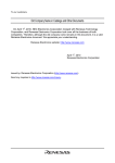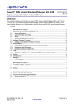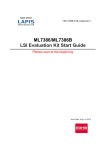
1
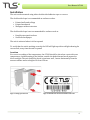
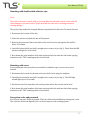
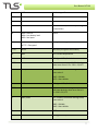
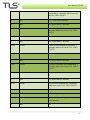
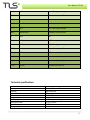
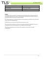
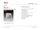
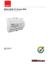
User Manual AT100 AT100 Wireless temperature sensor for indoor use User manual 1 User Manual AT100 All the information in this manual is applicable at the time of publication and may be subject to changes without notice. We recommend that prior to the installation you make sure that you have the most recent edition. The document may contain errors. TLS Energimätning is not responsible for damages, obligations or losses caused by the use of this product. This document may not be copied, in its entirety or in part. Contact: TLS Energimätning AB Sankt Eriksgatan 117A 11343 Stockholm, Sweden [email protected] www.tls.se www.tls.se 2 User Manual AT100 Innehållsförteckning Installation .............................................................................................................................................. 4 Location ............................................................................................................................................................... 4 Mounting with double-‐sided adhesive tape ............................................................................................ 5 Mounting with screw ...................................................................................................................................... 5 Encryption codes and password ................................................................................................................. 5 Usage .......................................................................................................................................................... 6 Mobile phones with NFC funktion ............................................................................................................. 6 Communication ...................................................................................................................................... 6 Message formats ............................................................................................................................................... 6 Technical specifications ...................................................................................................................... 9 Safety ...................................................................................................................................................... 10 Introduction AT100 is a wireless sensor for air temperature for indoor use. The sensor reads and transmits regularly the temperature to a wireless MBUS master that stores the readings. The unit also contains an electronic seal, which indicates if someone has been manipulating the unit. Order and purchase To facilitate the installation, we recommend that you order the units with or without encryption activated, to avoid configuration at the point of installation. Order code: Encryption: AT100-‐E YES At100-‐NE NO 3 User Manual AT100 Installation The unit can be mounted using either double-‐sided adhesive tape or a screw. The double-‐sided tape is recommended on surfaces such as: • • • Painted walls and ceilings Painted woodwork Wallpaper without structure The double-‐sided tape is not recommended for surfaces such as: • • Roughly structured surfaces Structured wallpaper The unit is activated when it is first opened. To verify that the unit is working correctly the LED will light up with a red light showing for ten seconds, every time the unit is opened. Location For correct recording of the temperature, the AT100 should be placed on a spot with even temperature. Avoid mounting in the kitchen, outside the bathroom and areas exposed to direct sunlight. The unit should be placed on an inner wall, 1 meter horizontally from the nearest radiator and at a height of at least 150 cm. Figur 1: taking apart the unit Figur 2: identification and serial number of the unit 4 User Manual AT100 Mounting with double-‐sided adhesive tape Note! The back of the unit is coated with very strong adhesive tape and removal of the unit will cause damage to the wall surface. Please note that the unit can be exchanged without causing damage. The product has industrial strength adhesive tape attached to the back. To mount the unit: 1. Determine the location of the unit. 2. Clean the surface on which the unit will be placed. 3. Remove the protective film on the back of the unit. Press the unit against the wall for ….about 10 seconds. 4. Carefully loosen the lid and pull it straight out to remove it (see fig. 1). Check that the LED ….shows a red light for 10 seconds. 5. Note down the serial number of the unit and press back the unit into the holder, paying attention to the ”TOP”-‐marking on the circuit board. Mounting with screw For mounting the unit on surfaces not suitable for adhesive tape, screws can be used instead. 1. Determine the location for the unit and centre drill a hole using the template. 2. Carefully loosen the lid and pull it straight out to remove it (see fig. 1). The LED light ….should light up for 10 seconds. 3. On the bottom of the unit there are weaker points where the screws can be used. 4. Note down the serial number of the unit and press back the unit into the holder, paying attention to the ”TOP” marking on the circuit board. Encryption codes and password For security reasons, all the encrypted AT100 are delivered with different encryption codes. The codes are delivered digitally in a .csv file for import to the reading system. 5 User Manual AT100 Usage Mobile phones with NFC (Near Field Communication) can be used to gain information about the current temperature by tagging or touching the unit with the back of the mobile phone. Mobile phones with NFC function 1. Activate the NFC through the phone settings 2. Drag the back of the phone slowly towards the unit. As the antennas align, a link will open on the phone, showing the temperature reading. Communication The unit regularly sends wireless messages with current temperature in a settable interval; the messages are in conformity with the Wireless M-‐Bus standard EN 13757-‐4 in T1 Mode. Each message includes: ·∙ Average temperature since the previous message ·∙ 1 hour continuous Average/Max/Min ·∙ 24 hours continuous Average/Max/Min ·∙ Serial number of the unit ·∙ MBUS Unique Identification Number ·∙ Battery status ·∙ Electronic seal Message formats The messages below are described in plain text. Fields marked with green will be encrypted if encryption is activated. For detailed information see EN 13757-‐4. Byte Value (default) Description 0 0xnn L-‐field 1 0x44 C-‐field 2-‐3 0x5193 Manufacturer ”TLS” 4-‐7 0xnnnnnnnn MBUS Identification Number 8 0x01 Protocol version number 6 User Manual AT100 9 0x1B Product type. Room sensor 10-‐11 0xnnnn CRC 12 0x7A CI-‐field 13 0xnn Access number (increased by each regular transmission) 14 0x00 = Normal …………………………….. 0x04 = Low battery level …………………. 0x03 = Seal open Status 15-‐16 0x0000 = Not Encrypted …………………. 0x???? = Encrypted Encryption settings 17-‐18 0x2f2f Idle filler (encryption verification) 19 0x02 DIF: Current temperature 20 0x65 VIF: signed 16bit, 2 decimals 21-‐22 0xnnnn Current temperature with 2 decimals, when error set to 0. Ex. 2310 = 23,10°C 23 0x42 / 0x72 DIF: 1 hour continuous average value, store value 1. 0x42 = Reliable.. ………………………………. 0x72 = Non-‐reliable 24 0x65 VIF: signed 16bit, 2 decimals 25-‐26 0xnnnn 1 hour continuous average temperature with two decimals, when error set to 0. Ex. 2310 = 23,10°C 27 0x82 / 0xb2 DIF: 24 hours continuous average value, store value 1. 0x82 = Reliable.……………………………….. 0xb2 = Non-‐reliable 28 0x01 DIFE 29 0x65 VIF: signed 16bit, 2 decimals 7 User Manual AT100 30-‐31 0xnnnn 24 hours continuous average temperature, 2 decimals, when error set to 0. Ex. 2310 = 23,10°C 32 0x22 DIF: 1 hour continuous Min 33 0x65 VIF: signed 16bit, 2 decimals 34-‐35 0xnnnn 1 hour continuous Min-‐temperature, 2 decimals, when error set to 0. Ex. 2310 = 23,10°C 36 0x12 DIF: 1 hour continuous Max. 37 0x65 VIF: signed 16bit, 2 decimals 38-‐39 0xnnnn 1 hour continuous Max-‐temperature, 2 decimals, when error set to 0. Ex. 2310 = 23,10°C 40 0x52 DIF: 24 hours continuous Min, store value 1 41 0x65 VIF: signed 16bit, 2 decimals 42-‐43 0xnnnn 24 hours continuous Min-‐temperature, 2 decimals, when error set to 0. Ex. 2310 = 23,10°C 44 0x62 DIF: 24 hours continuous Max, store value 1 45 0x65 VIF: signed 16bit, 2 decimals 46-‐47 0xnnnn 24 hours Max-‐temperature, 2 decimals, when error set to 0. Ex. 2310 = 23,10°C 48 0x01 DIF 49 0x7F VIF: 8bit signed integer 50 0xnn Number of seal breakings, accumulated at each opening. 51 0x42 DIF 8 User Manual AT100 52 0x7F VIF: 16bit signed integer 53-‐54 0xnnnn Manufacturer specific 55 0x84 DIF 56 0x01 DIFE 57 0x7F VIF: 32bit signed integer 58-‐61 0xnnnnnnnn Hardware serial number 62 0xC2 DIF 63 0x01 DIFE 64 0x7F VIF: 16bit signed integer 65-‐66 0xnnnn Manufacturer specific 67 0x84 DIF 68 0x02 DIFE 56 0x7F VIF: 16bit signed integer 57-‐60 0xnnnn Manufacturer specific Technical specifications Manufacturer Product name Material Protection class Measurements Weight Battery type Battery life time Operation temperature Storage temperature TLS Energimätning AB AT100 ABS UL94-‐HB IP20 71x71x27 mm 50 g Lithium (non-‐rechargeable) Up to 12 years 0-‐55°C -‐10 -‐ 55°C 9 User Manual AT100 Temperature accuracy 18-‐24°C Temperature accuracy 0-‐55°C M-‐Bus standard Transmission effect Frequency ±0,3K ±0,5K EN13757-‐4 (T1 Mode) 10 mW 868,95 MHz Safety AT100 must only be installed by competent personnel and all safety instructions must be followed during installation and use. Documentation regarding the installation and use of the product shall be forwarded to parties involved. The battery must not be recharged and may only be replaced by qualified service personnel approved by TLS Energimätning. Installation or use may not start until the instructions are read. The circuit board is sensitive to static electricity; hence during the installation the circuit board must not be touched without the use of ESD bracelets or similar. The product markings may not be removed, amended or in any other way made unidentifiable. 10