1
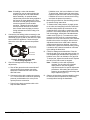
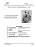
Installation Instructions
Issue Date
GM-7000
November 9, 2012
GM-7000 Series CE Approved Gas Control Valve
Installation
IMPORTANT: These instructions are intended as a
guide for qualified personnel installing or servicing
BASO Gas Products. Carefully follow all instructions
in this bulletin and all instructions on the appliance.
Limit repairs, adjustments, and servicing to the
operations listed in this bulletin or on the appliance.
4.
Compare the voltage on the valve with the power
source voltage to ensure the correct unit is being
installed.
5.
Mount the valve. The GM-7000 valve may be
mounted on a horizontal manifold with the
magnetic operators (solenoid coils) pointed up
(vertical) or in any position not exceeding 90°
from the vertical (Figure 1). The valve may also
be mounted on a vertical manifold in any position
around its axis. Do not install the solenoid coils
upside down. Install vertically wherever possible.
6.
If you desire to measure the outlet pressure, use
the bottom cast pressure test fitting.
!
WARNING: Risk of Fire or Explosion.
The system must meet all applicable local, national,
and regional regulations. Improper installation may
cause gas leaks, explosions, property damage, and
injuries.
90° Maximum
from Vertical
90° Maximum
from Vertical
!
WARNING: Risk of Fire or Explosion.
To prevent leakage of upstream gas, shut off the gas
supply at the main manual shutoff valve before
installing or servicing the GM-7000 valve. Failure to
shut off the gas supply can result in the release of
gas during installation or servicing, which can lead to
an explosion or fire, and may result in severe
personal injury or death.
Limited Horizontal and Vertical
Mounting
!
CAUTION: Risk of Equipment Damage.
To prevent damage to the valve when mounting to
pipework, do not use a wrench on any surface other
than the casting flats provided at the inlet and outlet
ends of the valve body.
Vertical mounting may
be 360º around its axis
with the gas flow either
up or down, but always in
the direction of the arrow.
To install the GM-7000 valve:
1.
Shut off power to the appliance.
2.
Shut off the gas at the main manual shutoff valve.
3.
Label each wire with the correct terminal
designation prior to disconnection.
© 2012 BASO Gas Products
Part No. BASO-INS-GM7000, Rev. F
7.
Figure 1: GM-7000 Mounting Positions
Install the valve on the manifold; ensure the gas
flows through the valve body in the direction
indicated by the arrow on the body. If the valve is
installed with the gas flow in the opposite
direction of the arrow, leakage can occur.
1
www.baso.com
8.
Note: If installing a valve with threaded
connections, use an approved pipe joint
sealing compound on the male threads
before assembly. An optional thread
lubricant may have been factory applied to
the first two or three threads of the inlet
and outlet to avoid galling. Make sure that
excess compound is removed after
mounting. Threads of pipe and nipples
must be smooth and free of tears and
burrs. Steam clean all piping to remove
foreign substances such as cutting oil or
thread chips.
Connect the pilot tubing (when necessary) to the
threaded pilot connection on the underside of the
valve body (Figure 2) and run the tube to the pilot
burner within the appliance. Connect the pilot
tube to the valve with an optional compression
fitting.
10.
11.
Outlet Pressure
Tap Connection
12.
Pilot Tube
Connection
9.
Figure 2: Underside of Valve with
Direct-Acting Regulator
Check for leakage before making any valve
adjustments.
a. Shut off the gas at the main manual shutoff
valve and open the pressure connection
between the manual shutoff valve and the
GM-7000 valve.
b. Connect air tubing with a maximum pressure
of 1-1/2 times the valve’s maximum operating
pressure (as indicated on the valve) to the
opened pressure connection.
13.
If bubbles occur, this is an indication of a leak.
To stop a leak, tighten joints and connections.
Replace the part if the leak cannot be stopped.
If bubbles do not occur, remove the air tubing
and close the pressure connection.
Make wiring connections. See the Wiring section
for specific wiring instructions.
To measure the outlet pressure, by apply power
to the valve and energizing both valve solenoids.
Use the outlet pressure tap connection on the
underside of the valve body to monitor the outlet
pressure. The outlet pressure tap is a bleed hole
with a cast spigot, sealed with a threaded brass
needle screw (Figure 2). To measure the outlet
pressure, turn the screw in a counterclockwise
direction one or two turns and fit a 9 mm diameter
flexible tube over the cast spigot. After all valve
adjustments have been made and the desired
outlet pressure has been obtained, remove the
flexible tube. Tighten the needle screw by turning
it clockwise with a slotted screwdriver until hand
tight, sealing the bleed hole.
Check for leakage at the bleed hole. Paint the
bleed hole with a rich soap and water solution (or
use acceptable gas leak detection equipment). If
bubbles occur, this is an indication of a gas leak.
To stop a leak, tighten the needle screw. Replace
the valve if the leak cannot be stopped.
Note: If installing a valve with a pressure
regulator, set the valve to the desired
outlet pressure. See the Regulator
Adjustment section for specific adjustment
procedures. After setting the valve outlet
pressure, ensure that the leak-limiting seal
cap is replaced (Figure 3).
Observe at least three complete operating cycles
to ensure that all components are functioning
correctly before leaving the installation.
c. Paint all valve body connections with a rich
soap and water solution.
2
GM-7000 Series CE Approved Gas Control Valve Installation Instructions
Earth Ground
L2
Line 2
N2
Coil 2
Main
Valve
Neutral
Line 1
N1 Coil 1
Pilot
L1 Valve
Twin Solenoid Wiring Using 4-Wire Cable
Non-Polarity Sensitive
Line and Neutral
Connections
Non-Polarity Sensitive
Line and Neutral
Connections
Ground Tab (Optional)
Ground Tab (Optional)
Leak-Limiting
Seal Cap
To Pilot Solenoid
L
N
To Main Solenoid
L
N
Figure 3: GM-7532 Model with Direct-Acting Regulator
GM-7000 Series CE Approved Gas Control Valve Installation Instructions
3
Wiring
4.
Turn the thermostat to a low dial setting to open
the contacts. All burner flames should be
extinguished. Repeat Steps 3 and 4 at least three
times.
5.
Return the thermostat to a normal setting before
leaving the installation.
!
CAUTION: Risk of Electric Shock.
Disconnect power supply before making electrical
connections to avoid electric shock or equipment
damage. Ensure that the operating voltage is
identical to the information on the product
identification label.
The GM-753_ is supplied with 6.35 x 0.8 mm (1/4 in.)
male tabs, and connections should be made using
6.35 x 0.8 mm (1/4 in.) female, fully insulated push-on
terminals.
Route the electrical connection for the valve solenoid
actuators from the burner sequence control to the
valve (see Figure 3).
Note: Electrical connections can also be made using
pre-wired electrical plugs (DIN 43650 Form B [ISO
4400]).
Note: All wiring must be in accordance with national
and local codes and regulations.
Setup and Adjustments
Checkout
!
WARNING: Risk of Explosion or Fire.
Follow this or an equivalent checkout procedure
after installation. Before leaving the installation,
verify that the gas valve functions properly and that
the system has no gas leaks. Gas leaks can lead to
an explosion or fire, and may result in severe
personal injury or death.
Regulator Adjustment
IMPORTANT:
All adjustments must be made
in conjunction with the gas appliance and in
accordance with the appliance manufacturer’s
instructions. Only authorized personnel should make
adjustments.
!
WARNING: Risk of Explosion or Fire.
The minimum flow rate of the valve must not be
adjusted below the minimum safe working rate of the
appliance. This may cause gas leaks, which can
lead to an explosion or fire and may result in severe
personal injury or death.
The GM-753_ model has a bottom adjust pressure
regulator. To adjust the regulator, turn the adjusting
screw to determine the compression of the regulator
spring against the regulator diaphragm.
To adjust the outlet pressure, remove the leak-limiting
seal cap to expose the adjusting screw (Figure 3).
Turn the screw (using a suitable screwdriver) in a
clockwise direction to increase or in a
counterclockwise direction to decrease the outlet
pressure of the valve.
Repairs and Replacement
Table 1: Replacement Solenoid Coil
Make sure all components are functioning properly by
performing the following test:
1.
2.
3.
4
Test all joints and connections for leaks with a
soap solution.
Close the main upstream shutoff valve and wait
at least 5 minutes for unburned gas to escape
from the appliance, and then reopen the shutoff
valve.
Turn on the main electrical power switch and
close the thermostat contacts. The appliance
should operate in accordance with the
manufacturer’s specified sequence of operation.
Part Number
Description
RSDA95A-25
25 VAC; 50/60 Hz; 3-tab 10.5 VA Coil
RSDA95A-25A
25 VAC; 50/60 Hz; 2-tab 10.5 VA Coil
Do not make field repairs except for the replacement
of the solenoid coil.
Any attempt to repair this assembly voids the
manufacturer’s warranty. For a replacement coil or gas
valve, contact the original equipment manufacturer or
the nearest BASO Gas Products distributor.
GM-7000 Series CE Approved Gas Control Valve Installation Instructions
Technical Specifications
Product
GM-7000 Series CE Approved Gas Control Valve
Types of Gas
Natural, Liquefied Petroleum (LP), and LP gas-air mixtures
Rated Inlet Pressure
North America:
Europe:
Australia:
1/2 psi
35 mbar
3.5 kPa
Maximum Working
Pressure (CE)
50 mbar
Maximum Differential
Pressure
20 mbar (2 kPa [8 in. W.C.])
Reverse Pressure Rating
50 mbar (5 kPa [20 in. W.C.]) Class B (EN 126 and 161); Class 2 (AS 4624 and AS 4629)
Regulator Classification
Class C (EN 126); Adjustable, Class 2, Grade 20 (AS 4624)
Regulator Setting
Factory set to customer’s specification
Direct-Acting Regulator
Pressure Range
Natural Gas:
LP Gas:
Permissible Ambient
(Surface) Temperature
0 to 70°C (32 to 158°F )
7.5 to 12.5 mbar (0.15 to 1.25 kPa [3 to 5 in. W.C.])
22.5 to 30 mbar (2.25 to 3 kPa [9 to 12 in. W.C.])
Body Connections
1/2 NPT, 1/2 BSPP (Thread ISO 7-Rp) or 1/2 BSPT (Thread ISO 7-Rc) with Flange Connection Holes
(M4 x 0.7 mm pitch x 6 mm deep)
Valve Torsion Group
Group 2 (EN 126 and 161)
Pressure Taps
M5 x 0.8 Thread
Pilot Connection
1/4 in. cc Blank Plug
Materials
Body:
Diaphragms and Seals:
Dirt Strainer
0.9 mm (0.036 in.) mesh (CE only or upon request)
Operating Time Rating
100% Continuous
Valve Timings
Closing Time:
Opening Time:
Dead Time:
Power Rating
10.5 VA per Coil
Electrical Rating
25 VAC, 50/60 Hz, 0.42A
Electrical Connection
2-Tab Solenoid Coil: 2 x 6.35 mm (1/4 in.)
3-Tab Solenoid Coil: 2 x 6.35 mm (1/4 in.) + 6.35 mm (1/4 in.) Earth Ground
Coil Insulation Class
Class F
Accessories
Conversion Kits
Die-Cast Aluminum
Nitrile Rubber
< 1 Second
< 1 Second
< 1 Second
Natural gas to LP gas:
LP gas to Natural gas:
Regulated to non-regulated:
GM-70-CLP
GM-70-CNG
BG-70-CBP
GM-7000 Series CE Approved Gas Control Valve Installation Instructions
5
Technical Specifications (continued)
Agency Listings
CSA (AGA/CGA) Certificate Number 229521-1656041
EC Certificate Number EC-86/11/041
Australian Gas Association Certificate Number 7934
Specification
Standards
EN 126 and 161
Standards Complying with the Directive
Standards Complying with the Low Voltage Directive
Australian Standards AS 4624 and AS 4629
Canadian Standard CSA 6.5 and 6.20
ANSI Standards Z21.21 and Z21.78
Performance specifications are nominal and conform to acceptable industry standards. All agency certification of BASO products is performed
under dry and controlled indoor environmental conditions. Use of BASO products beyond these conditions is not recommended and may void
the warranty. Product must be protected if exposed to water (dripping, spraying, rain, etc.) or other harsh environments. The original
equipment manufacturer or end user is responsible for the correct application of BASO products. Consult BASO Gas Products LLC for
questionable applications. BASO Gas Products LLC shall not be liable for damages or product malfunctions resulting from misapplication or
misuse of its products.
Refer to the GM-7000 Series CE Approved Gas Control Valve Product Bulletin (BASO-PB-GM7000) for necessary information on operating
and performance specifications for this product.
th
1007 South 12 Street
PO Box 170
Watertown, WI 53094
1-877-227-6427 (1-877-BASOGAS)
6
GM-7000 Series CE Approved Gas Control Valve Installation Instructions
www.baso.com
Published in U.S.A.