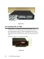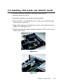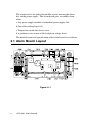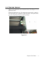
1
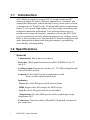
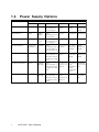
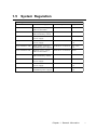
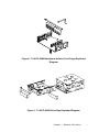
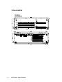
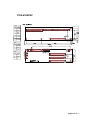
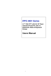
ACP-2000
19" Rackmount 2U Height
Industrial Chassis User's Manual
Copyright notice
This document is copyrighted, 2002, by Advantech Co., Ltd. All rights
are reserved. Advantech Co., Ltd. reserves the right to make improvements to the products described in this manual at any time without
notice.
No part of this manual may be reproduced, copied, translated or
transmitted in any form or by any means without the prior written
permission of Advantech Co., Ltd. Information provided in this manual
is intended to be accurate and reliable. However, Advantech Co., Ltd.
assumes no responsibility for its use, nor for any infringements upon
the rights of third parties which may result from its use.
Acknowledgements
• AWARD is a trademark of AWARD Software, Inc.
• IBM and PC are trademarks of International Business Machines
Corporation.
• Intel® and Pentium® III are trademarks of Intel Corporation.
• MS-DOS is a trademark of Microsoft Corporation.
• SMC is a trademark of Standard Microsystems Corporation.
• WinBond is a trademark of Winbond Corporation.
• VIA is a registered trademark of VIA Technologies Inc.
• Adaptec is a registered trademark of Adaptec Inc.
All other product names or trademarks are the properties of their
respective owners.
Part No. 200202K000
1st Edition Printed in Taiwan
January 2002
Contents
Chapter 1 General Information ...................................... 1
1.1
1.2
1.3
1.4
1.5
1.7
1.6
Introduction .......................................................................... 2
Specifications ........................................................................ 2
Passive Backplane Options ................................................ 3
Power Supply Options ......................................................... 4
System Regulation ............................................................... 5
Exploded Diagram ............................................................... 6
Dimensions ........................................................................... 6
Chapter 2 System Setup ................................................ 9
2.1 System Installation ............................................................. 10
2.1.1 Attaching the handles. ............................................... 10
2.1.2 Removing the top cover ............................................ 10
2.1.3 Front and Rear Sections of the Chassis .................... 11
2.1.4 Drive Bay Installation .................................................... 13
2.2 ACP-2000 Series Installation ........................................... 14
2.2.1 ACP-2000P3-00P, ACP-2000P4-00P ....................... 14
2.2.2 ACP-2000P3-00X, ACP-2000P4-00X ...................... 15
2.3 System Status Indicators .................................................. 16
2.4 Power Supply ...................................................................... 17
2.5 Cooling Fan & Filter ......................................................... 18
2.6 Installing CPU Cards and Add-On Cards ...................... 19
Chapter 3 Alarm Board ................................................ 21
3.1
3.2
3.3
3.4
Alarm Board Layout .......................................................... 22
Alarm Board Specification ................................................ 23
Switch Setting ..................................................................... 26
Thermal Sensor .................................................................. 27
Appendix A ................................................................... 29
PCA-6106P3V .......................................................................... 30
PCA-6105P4V .......................................................................... 31
Figure
Figure 1.7-1 ACP-2000 Full Exploded Diagram ............................................................ 6
Figure 1.7-3 ACP-2000 Driver Bay Exploded Diagram ................................................ 7
Figure 1.7-2 ACP-2000 Backplane Holder (Card Cage) Exploded Diagram ................. 7
Figure 2.1.2-1 ............................................................................................................... 10
Figure 2.1.3-2 ............................................................................................................... 11
Figure 2.1.3-3 ............................................................................................................... 11
Figure 2.1.3-4 ............................................................................................................... 12
Figure 2.1.4-1 ............................................................................................................... 13
Figure 2.2.1-1 ............................................................................................................... 14
Figure 2.2.2-1 ............................................................................................................... 15
Figure 2.2.2-2 ............................................................................................................... 16
Figure 2.4-1 .................................................................................................................. 17
Figure 2.4-2 .................................................................................................................. 18
Figure 2.5-1 .................................................................................................................. 18
Figure 2.6-1 .................................................................................................................. 19
Figure 2.6-2 .................................................................................................................. 19
Figure 3.1-1 .................................................................................................................. 22
Figure 3.4-1 .................................................................................................................. 27
CHAPTER
1
General Information
1.1
Introduction
ACP-2000 is a compact yet rugged 19" 2U height rackmount IPC
chassis designed for space-conscious applications. Customers can
expand their businesses without having to worry about space efficiency because the ACP-2000 is only 2U height and satisfies requirements
from CT, voice portal, high-density voice processing, networking and
industrial automation applications. Fast-growing Internet service
providers and corporate enterprise customers can use the ACP-2000
as e-server platforms for their internet/intranet, proxy, caching, access,
DNS, or file and print server. The ultra-thin 2U form factor delivers rack
space optimization without sacrificing performance, expandability,
serviceability, or manageability
1.2 Specifications
General
· Construction: Heavy duty steel chassis
· Drive bay: Shock-proof and front accessible CD-ROM (x1) & 3.5"
bay (x2)
· Cooling system: Dual easy-to-replace 42 ~ 57 CFM cooling fan with
front-accessible air filter
· Controls: Power On/Off switch or momentary switch
Reset switch behind lockable door
· Indicators:
· Power: Bi-color LED (green/red) for power failure
· HDD: Single color LED (orange) for HDD activity
· Fan: Bi-color LED (green/red) for any fan failure
· Temperature: Bi-color LED (green/red) for overheating average
temperature 50°C
· Connectors: Front accessible USB and PS/2 keyboard, rear panel 9pin connectors
2
ACP-2000 User's Manual
· Paint Color: Pantone 4C 2X Black, textured
· Operating temperature: 0 ~ +40°C (32°F ~ 104°F)
· Storage temperature: -40° to +75°C (-40° to +167°F)
· Relative Humidity: 10 ~ 95%@40?, non-condensing
· Vibration: (Operating) 5Hz ~ 500Hz, 0.5 G rams
· Random Vibration: (Non-operation) 5 to 20 Hz, 0.001 to 0.01 G2 per
Hz, 20 to 500 Hz, 0.01 G2 per
· Shock(operating): 2.0 G with 11m Sec duration, 1/2 sine wave
· Acoustic Noise: Less than 52 dB sound pressure at +5° to +28°C
(+41° to +82°F)
· Altitude:0 to 3048m (0 to 10,000 ft)
· Slide rails: General Device C-300 series supported
· Dimensions: 482 (W) x 88 (H) x 450 (D) mm or 19" (W) x 3.46" (D) x
17.7" (H)
· Weight: 9.8kg.(21.6lb)
· Safety: CE compliant, UL/cUL approved
1.3 Passive Backplane Options
Backplane models (refer to appendix for details)
· PCA-6106P3V:
CPU/ 2-ISA/ 3-PCI
· PCA-6105P4V:
CPU/ 4-PCI
Chapter 1 General Information
3
1.4
Power Supply Options
Model Name
Specifications
Watt
Input
Output
Mini- load
PS- 260- 610E(AT)
260W
110/220Vac
+5V@
25A+12V@9A- [email protected] 12V@2A
+5V@1A+12V- UL/CSA/[email protected]
E/TUV
PS- 250- D24(AT)
250W
+19VDC ~
+32VDC
+5V@
+5V@1A
30A+12V@12A- 5V@ 2A- 12V@2A
UL/CSA/CE 100,000 hours
PS- 310- DC48(AT)
310W
- 38VDC ~ - +5V@
+5V@2A
58VDC
25A+12V@10A- 5V@ 1A- 12V@5A
UL/CSA/CE 100,000 hours
PS- 250X- DPS(ATX)
250W@25°C- 110/220Vac
/200W@50°C
[email protected],+1- UL, CSA,
+5V@
TUV/CE/N25+12V@8A- 5V@- [email protected]
0.5A- [email protected]+3.ordic/CB,
3V@14A+5Vsb@1A
PS- 300- ATX(ATX)
300W
110/220Vac
+5V@1A+12V- UL,CSA,T- 100,000
+5V@
30A+3.3V@26A+1- @0.2A
UV/CE/Nor- hours@25°Cfdic/CB
ull load
2V@13A- [email protected],- [email protected],+5Vsb@ 2A
PS- 300ATX- Z(ATX,PFC)
300W
110/220Vac- +5V@
+5V@1A,+12(Full- range) 30A+3.3V@24A+1- [email protected],+3.32V@15A- [email protected] [email protected]
A,- [email protected],+5Vsb@ 2A
RPS- 300ATX- Z(ATX PFC) 300W
4
Safety
MTBF
140,000
hours@50°Cfull load
100,000
hours@25 °C
full load
UL,cUL,CS- 100,000hoursA,CE
@25°C 275W
EN61000- 3- - load
2 Class
DTUV,Nordic,CB
110/220Vac- +5V@
+5V@3A+3.3- UL/TUV/CB 150,000hours(Full- range) 25A+3.3V@18A+1- V@1A
@25°C full
2V@16A- [email protected] +12V@2A+5Vload
A,- [email protected],+5VS- [email protected]
B@2A
ACP-2000 User's Manual
1.5
System Regulation
O rdering Information
Model name
With Power Supply
With Backplane
Regulation
ACP- 2000P3- 00P
Without power supply,
with on- off switch
With PCA- 6106P3V
N one
ACP- 2000P3- 00X
Without power supply,
with momentary switch
With PCA- 6106P3V
N one
ACP- 2000P3- 30Z
With 300W ATX PFC
power supply
With PCA- 6106P3V
UL.cUL,CE
ACP- 2000P3- 30D
With 300W DC48V
power supply
With PCA- 6106P3V
UL, cUL,
CE
ACP- 2000P3- 30R
With 300W ATX PFC
redundant power supply
With PCA- 6106P3V
UL, cUL,
CE
ACP- 2000P4- 00P
Without power supply,
with on- off switch
With PCA- 6105P4V
N one
ACP- 2000P4- 00X
Without power supply,
with momentary switch
With PCA- 6105P4V
N one
ACP- 2000P4- 30Z
With 300W ATX PFC
power supply
With PCA- 6105P4V
UL.cUL,CE
ACP- 2000P4- 30D
With 300W DC48V
power supply
With PCA- 6105P4V
UL, cUL,
CE
ACP- 2000P4- 30R
With 300W ATX PFC
redundant power supply
With PCA- 6105P4V
UL, cUL,
CE
Chapter 1 General Information
5
1.6
Dimensions
1.7
Exploded Diagram
Figure 1.7-1 ACP-2000 Full Exploded Diagram
6
ACP-2000 User's Manual
Figure 1.7-2 ACP-2000 Backplane Holder (Card Cage) Exploded
Diagram
Figure 1.7-3 ACP-2000 Driver Bay Exploded Diagram
Chapter 1 General Information
7
8
ACP-2000 User's Manual
CHAPTER
2
System Setup
2.1 System Installation
WARNING: Before starting the installation process, be sure to
shut down all power from the chassis. Do this by
turning off the power switch, and unplugging the
power cord from the power outlet. When in doubt,
consult with an experienced technician.
2.1.1 Attaching the handles.
The handles for the front panel are in the accessory box. To install the
handles, simply secure them to the front panel with the provided
screws.
2.1.2 Removing the top cover
The first installation step is removing the chassis cover. You will need
a Phillips screwdriver.
The top cover is fixed to the chassis with six (6) M4 screws.
To remove the top covers:
1.Detach the six screws on the chassis.
2.Lift off the cover.
Figure 2.1.2-1
10
ACP-2000 User's Manual
2.1.3 Front and Rear Sections of the Chassis
The front panel switches located behind the door are used for system
power, system reset and alarm reset. On the left side of front panel,
there are system LED status, USB and P/S 2 keyboard connector. On
the left side of the front panel is the door cover with a key lock.
System Reset Switch
Alarm Reset Switch
Power On/Off Switch or Momentary Switch
Figure 2.1.3-1
Figure 2.1.3-2
Figure 2.1.3-3
Chapter 2 System Setup
11
Power On/Off Switch: Use this switch to turn on/off the system
power.
Momentary Switch: Using the ATX (PS_ON) function, turn on the
system power.
Please use the system shutdown to turn off system power automatic,
or press momentary switch to turn off the system power.
System Reset Switch: Press this switch to reinitialize the system,
which is the same as the hardware reset button.
Alarm Reset Switch: Press this switch to pause or stop an audible
alarm. Whenever a fault in the system occurs
(e.g. fan failure, rising chassis temperature, backplane voltage problem), an audible alarm is activated. Pressing this switch will cause the
alarm to stop.
USB connector: Used in connecting USB interface device to the
system.
PS/2 connector: Used in connecting PS/2 keyboard.
The Rear Section includes: 6-slot I/O bracket, DB-9 bracket and PS/2
or redundant power supply
Figure 2.1.3-4
12
ACP-2000 User's Manual
2.1.4 Drive Bay Installation
The ACP-2000 standard drive bay can hold one slim-type CD-ROM,
and two 3.5" bay or 5.25" bay & one 3.5" bay.
Installation disk drives
a.Remove the Top Front Cover
b.Undo the six screws fixing the Standard Drive Bay.
c.Lift off the Standard Drive Bay. See Figure 2.1.4-1
d.Insert the drives into their proper locations in the drive bay, and
secure with the provided screws.
e.Connect the disk drive power and signal cables.
Figure 2.1.4-1
Chapter 2 System Setup
13
2.2 ACP-2000 Series Installation
The ACP-2000 can be of two basic models: ACP-2000P3 series and
ACP-2000P4 series.
2.2.1 ACP-2000P3-00P, ACP-2000P4-00P
ACP-2000P3-00P comes with the PCA-6106P3V backplane, and ACP2000P4-00P with the PCA-6105P4V-B backplane. Both of them are
without power supply installation, but with on-off switch on the front
panel. The on-off switch is suitable for AT power supply such as PS250, PS-260, PS-300, PS-310DC48 and PS-250-D24. Refer to figure 2.2.11 for reference. (ACP-2000P4-00P, PCA-6105P4V-B will be available on
Q2/2002)
Figure 2.2.1-1
14
ACP-2000 User's Manual
2.2.2 ACP-2000P3-00X, ACP-2000P4-00X
The ACP-2000P3-00X comes with the PCA-6106P3V backplane, and
ACP-2000P4-00X with the PCA-6105P4V backplane. Both of them are
without power supply installation, but with momentary switch on front
panel. The momentary switch is suitable for ATX power supply such
as PS-250X-DPS, PS-300-ATX, PS-300ATX-Z and RPS-300ATX-Z.
For the ACP-2000P3-00X, please connect ATX power connector with
PCA-6106P3V backplane, then use the green-purple line (1703030250)
to connect J4 (5VSB_GND_PSON) of the Backplane and "ATX feature
connector" (CN20) of the SBC. Lastly, connect POWER SW line with
"ATX soft power switch"(CN21) of the SBC to finish the installation.
Refer the figure 2.2.2-1.
For the ACP-2000P4-00X, please connect the ATX power connector
with the PCA-6105P4V backplane, then use the orange-white line
(1700030500) to connect CN3 (PSON_GND_5VSB) of the Backplane
and "ATX feature connector" (CN20) of the SBC. Lastly, connect the
POWER SW line with "ATX soft power switch"(CN21) of the SBC to
finish the installation. Refer Figure 2.2.2-2 for reference.
Figure 2.2.2-1
Chapter 2 System Setup
15
Figure 2.2.2-2
2.3 System Status Indicators
The System Status LED shows as follows:
16
LED
Description
RED
GREEN or Orange
PWR
System Power
Abnormal
Normal
HDD
Hard Drive activity
No light
Data access
FAN
Cooling Fan status
Abnormal
Normal
TEMP
Chassis Temperature
Abnormal
Normal
ACP-2000 User's Manual
When the PWR LED is RED, it indicates a failure on redundant power
supply. To stop the alarm buzzer, press the Alarm Reset button. Please
check the redundant power supply right away, and replace power
failure supply module with a good one.
When the FAN LED is RED and blinking, it indicates a failing cooling
fan. An alarm is also activated. To stop the alarm buzzer, press the
Alarm Reset button then replace the fan immediately.
If the TEMP LED is RED and blinking, the system detects rising
temperature inside the chassis. An alarm is activated. To stop the
alarm buzzer, press the Alarm Reset button. Inspect the rear section
and fan filter immediately. Make sure airflow inside the chassis is
smooth and not blocked with dust or other particles.
2.4 Power Supply
ACP-2000 support PS/2 and redundant power supply both mechanical
without any modification
Figure 2.4-1
Chapter 2 System Setup
17
Figure 2.4-2
2.5 Cooling Fan & Filter
There are two (2) Cooling Fans located inside the chassis. The
Cooling Fans are easy to maintain and provide adequate cooling to the
system by blowing air inward. When one cooling fan breaks down,
the system sounds a continuous alarm. To disable the alarm, press the
Alarm Reset Switch on the front panel. Replace the failing fan immediately.
Please refer to figure 2.5-1 for filter replacement
Figure 2.5-1
18
ACP-2000 User's Manual
2.6 Installing CPU Cards and Add-On Cards
To install slot board computers and other add-on boards:
1.Remove the chassis cover.
2.From the backplane, take out the backplane holder.
3.Insert the CPU card from the left-side, or add-on card from the rightside, into the vacant slot.
4.Align and fix the screw to tighten the card to a fixed position, refer to
Figure 2.6-1 and Figure 2.6-2.
5.Return the backplane holder, with the backplane, CPU card or add-on
cards to the chassis.
Figure 2.6-1
Figure 2.6-2
Chapter 2 System Setup
19
20
ACP-2000 User's Manual
CHAPTER
3
Alarm Board
The alarm board is located in the middle section, between the driver
bay and the power supply. The alarm board gives an audible alarm
when:
a.Any power supply module of redundant power supply fails
b.One of the cooling fans fai1s
c.Temperature inside the chassis rises
d.A problem occurs in one of the backplane voltage levels
The detailed layout and specification of the alarm board are as follows
3.1 Alarm Board Layout
Figure 3.1-1
22
ACP-2000 User's Manual
3.2 Alarm Board Specification
Input Power: +5V, +12V
Input Signals:
• 7 FAN connectors
• One thermal board connector (can connect up to 8 thermal boards in
series way)
• One power good input
• One alarm reset input.
• One voltage signal connector (connect from back plane, includes
±12V, ±5V, 3.3V)
• One ATX power connector (connect from CPU card)
• One system reset connector (connect from CPU card)
• One Hard Disk LED connector (connect from CPU card)
Output Signals:
• One LED board connector
• One LCM board connector
• SNMP daughter board connector (connect to SNMP-1000 main
board)
• One Buzzer output
• ATX power connector (connect to chassis)
• System reset connector (connect to chassis)
Other Interfaces:
• One pair of Watch dog input/output signals
• One pair of I2C Bus signals (DATA and CLK)
• One LAN connector
• One COM connector
• One Battery pack connector
Pin Definition
CN1 : External Power Connector, stander mini 4 Pin power connector
Pin 1 : +12V, 2A current maximum
Pin 2 : GND
Pin 3 : GND
Pin 4 : +5V, 2A current maximum
Chapter 3 Alarm Board
23
CN2 : 10/100M LAN Connector
Pin 1 : SPLED
Pin 2 : TERMPLANE
Pin 3 : RX+
Pin 4 : RXPin 5 : GND
Pin 6 : LVCC
Pin 7 : TX+
Pin 8 : TXPin 9 : LILED
Pin 10 : TERMPLANE
Pin 11 : N/A
Pin 12 : NC
CN4 : I2C Sensor board (LM75) Connector
Pin 1 : +5V
Pin 2 : Sensor board I2C bus clock
Pin 3 : Sensor board I2C bus data
Pin 4 : GND
CN8 : RS-232 Connector
Pin 1 : DCD
Pin 2 : RX
Pin 3 : TX
Pin 4 : DTR
Pin 5 : GND
Pin 6 : DSR
Pin 7 : RTS
Pin 8 : CTS
Pin 9 : RI
Pin 10 : NC
Pin 11 : NC
Pin 12 : N/A
CN10 : LCM Display Board Connector
Pin 1 : LCM I2C bus data
Pin 2 : LCM I2C bus clock
Pin 3 : +12V
Pin 4 : GND
Pin 5 : +5V
Pin 6 : +5V
Pin 7 : Diagnostic LED
Pin 8 : GND
CN11 : SNMP-1000 Daughter Board Connector (Left side)
Pin 1 : SIN
Pin 2 : SOUT
Pin 3 : CTS#
Pin 4 : DCD#
Pin 5 : RTS#
Pin 6 : DTR#
Pin 7 : DSR#
Pin 8 : ID 0
Pin 9 : ATX ON
Pin 10 : DO 4
Pin 11 : GND
Pin 12 : DO 3
Pin 13 : Watchdog IN
Pin 14 : DO 2
Pin 15 : Watchdog OUT
Pin 16 : DO 1
Pin 17 : SPLED
Pin 18 : NC
Pin 19 : LILED
Pin 20 : NC
Pin 21 : GND
Pin 22 : NC
Pin 23 : TX+
Pin 24 : NC
Pin 25 : TXPin 26 : NC
Pin 27 : RX+
Pin 28 : NC
Pin 29 : RXPin 30 : NC
Pin 31 : TERMPLANE
Pin 32 : NC
24
ACP-2000 User's Manual
CN12 : SNMP-1000 Daughter Board Connector (Right side)
Pin 1 : NC
Pin 2 : NC
Pin 3 : Power Good A
Pin 4 : NC
Pin 5 : NC
Pin 6 : NC
Pin 7 : Diagnostic LED
Pin 8 : FAN 1
Pin 9 : GND
Pin 10 : FAN 2
Pin 11 : GND
Pin 12 : FAN 3
Pin 13 : VCC
Pin 14 : FAN 4
Pin 15 : VCC
Pin 16 : FAN 5
Pin 17 : VCC
Pin 18 : FAN 6
Pin 19 : BEEP
Pin 20 : FAN 7
Pin 21 : 5VSB
Pin 22 : NC
Pin 23 : -5V
Pin 24 : NC
Pin 25 : +5V
Pin 26 : B_SCLK
Pin 27 : +3.3V
Pin 28 : B_SDAT
Pin 29 : -12V
Pin 30 : T_SCLK
Pin 31 : +12V
Pin 32 : T_SDAT
CN13 : Voltage Detect Input Connector
Pin 1 : 5VSB
Pin 2 : GND
Pin 3 : GND
Pin 4 : -5V
Pin 5 : +5V
Pin 6 : +3.3V
Pin 7 : -12V
Pin 8 : +12V
CN16 : 4 bit Power Good Input
Pin 1 : Power GOOD A
Pin 2 : GND
CN18 : LED Board Connector
Pin 1 : GND
Pin 2 : +5V Signal
Pin 3 : +12V Signal
Pin 4 : -5V Signal
Pin 5 : -12V Signal
Pin 6 : HDD Signal
Pin 7 : Power Good Signal
Pin 8 : Power Fail Signal
Pin 9 : Temperature Good Signal
Pin 10 : Temperature Fail Signal
Pin 11 : Fan Good Signal
Pin 12 : FAN Fail Signal
Pin 13 : NC
Pin 14 : +3.3V Signal
Pin 15 : 5VSB Signal
CN19 : Connector bank from CPU card
Pin 1 : HDD LED Signal
Pin 2 : ATX soft power switch
Chapter 3 Alarm Board
25
Pin 3 : I2C Clock
Pin 4 : ATX soft power switch(-)
Pin 5 : I2C Data
Pin 6 : System Reset Signal
CN20 : Connector bank to Chassis
Pin 1 : ATX Momentary switch Pin 2 : ATX Momentary switch (-)
Pin 3 : GND
Pin 4 : System Reset Signal
Pin 5 : Watch Dog IN
Pin 6 : Watch Dog OUT
J1 : External Speaker
Pin 1 : Buzzer
Pin 2 : +5V
3.3 Switch Setting
Fan number setting
FAN
NUMBER
SW 1- 1
SW 1- 2
SW 1- 3
SW 1- 4
1
O FF
O FF
ON
O FF
2
O FF
ON
O FF
O FF
3
O FF
ON
ON
O FF
4
ON
O FF
O FF
O FF
5
ON
O FF
ON
O FF
6
ON
ON
O FF
O FF
7
ON
ON
ON
O FF
Thermal Board Temperature Setting
26
TEMP INDEX
SW 1 - 1
SW 1 - 2
SW 1 - 3
SW 1 - 4
TEMP 1
O FF
O FF
O FF
ON
TEMP 2
O FF
O FF
ON
ON
TEMP 3
O FF
ON
O FF
ON
TEMP 4
O FF
ON
ON
ON
TEMP 5
ON
O FF
O FF
ON
TEMP 6
ON
O FF
ON
ON
TEMP 7
ON
ON
O FF
ON
TEMP 8
ON
ON
ON
ON
ACP-2000 User's Manual
3.4 Thermal Sensor
There is one temperature sensor inside the chassis, See Figure 3.4-1.to
find the location.
When the temperature rises, the temperature sensor sends a signal to
the alarm board and a continuous alarm will sound. To stop the alarm,
press the Alarm Reset Switch on the Front Panel.
Figure 3.4-1
Chapter 3 Alarm Board
27
28
ACP-2000 User's Manual
Appendix
A
PCA-6106P3V
30
ACP-2000 User's Manual
PCA-6105P4V
CN2
PIN NAME
+5VSB
1
2
GND
3
GND
4
-5V
5
+5V
6
+3.3V
7
-12V
8
+12V
CN1
PIN NAME
1
2
PS-ON
GND
3
5V SB
CN3
PIN NAME
1
12V
2
GND
3
5V
Appendix A 31
32
ACP-2000 User's Manual