1
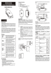
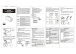
ZWRX-S Universal On/Off Sensor The ZWRX-S Universal On/Off Sensor is a Z-Wave™ device that is designed to work in most Z-Wave™ networks. The sensor has one input; it monitors the voltage on that input and translates it into Z-Wave™ commands. The Z-Wave™ software can see the sensor as being “off” or “on”. The sensor can be used to detect presence of voltage across its input pins, or it can be configured to work with passive contacts that are connected to those pins. The sensor can supply a limited amount of power to an external sensor. The Universal On/Off Sensor is a plug-in type device that is designed to operate on a 110/120V, 60 Hz AC circuit that is used in North America. The sensor is plugged into the wall outlet and operates entirely on utility power. The sensor is isolated from the ground with a Class II/Class III power transformer. Installation Procedure Select the location for the Universal On/Off Sensor The chosen location should have a wall outlet or a power strip available to power the device. When selecting the location take into account the distance to the Z-Wave™ controller or to neighboring Z-Wave™ nodes. The device will be unreachable if is installed too far from the controller or from routing nodes. Connect input wires to the plug of the input connector The Universal On/Off Sensor comes with a three-circuit plug that connects your signal to the sensor. Figure 2: The Input Plug Figure 1: The Universal On/Off Sensor To connect a wire to the plug: Strip the wire ¼ inch. Insert the stripped end into the opening, and then use a small flat screwdriver to tighten the screw. The wire will be securely connected. Page 1 of 7 The wire on the left (see Figure 2) is the power source wire (if you need it;) the wire in the center is the input wire; and the wire on the right is the common wire. Note that the common wire is not connected to the protective ground of the wall outlet. This legend is also printed on the sticker at the bottom of the device. up again for about a second, and after that it will switch back into the input monitoring mode. Plug the input connector into the Universal On/Off Sensor The pullup can be also controlled remotely, over the Z-Wave™ radio link. See the Programmer’s Manual for details. The plug can be easily inserted and removed from the Universal On/Off Sensor. The opening for the plug is on the bottom of the device (see Figure 1). Test the input circuit Plug the Universal On/Off Sensor into the wall outlet Insert the Universal On/Off Sensor into the wall outlet. If the Sensor is new and not yet included into the Z-Wave™ network, the yellow LED on the right side of the device starts blinking, and the Sensor is ready for network-wide inclusion. If the Sensor is already a part of the Z-Wave™ network, the LED will flash briefly, and after 10 seconds it becomes steady on or off, indicating the state of the sensor’s input. If a voltage is applied to the input the LED will be on, and the Z-Wave™ software will see the sensor as “on.” Enable or disable the internal pullup resistor The Universal On/Off Sensor has a built-in pullup resistor, to be used for detection of the state of passive contacts. The device is shipped with the pullup turned on. The pullup may be optionally deactivated if voltage levels are connected to the input. The sensor will be “off” if nothing is connected to the input, and “on” if the input pins are connected together. To toggle the pullup resistor hold the button on the side of the device for 5 to 10 seconds, then release. The LED will flash briefly if the pullup is turned off, or it will light up for half a second if the pullup is turned on. About 5 seconds after that the LED will light Page 2 of 7 The pullup state is stored within the sensor and will be retained even if the device is unplugged or if utility power is lost. Operate your input circuit and observe the yellow LED on the right side of the Universal On/Off Sensor. If there is no voltage across the input contacts, the LED will be “off”. If there is a voltage the LED will be “on”. If the pullup resistor is enabled, the LED will be “off” when the input contacts are free (or the plug removed) and the LED will be on when the input contacts are shorted together. Include the Sensor into the Z-Wave™ network Using the Network-Wide Inclusion: Plug the sensor into the wall outlet. The LED starts blinking fast. The sensor is now in the NWI mode. Activate the inclusion function on a NWI-capable controller to perform the inclusion. Once it completes, the LED stops blinking. Using the manual inclusion method: Bring the Z-Wave™ controller near the sensor and activate its inclusion mode. Press and release the button on the sensor. The LED will flash for a few seconds, and the sensor becomes a part of the Z-Wave™ network. Associate the Sensor with controlled (slave) device(s) Announcement of the node information This needs to be done only if the Z-Wave™ network is not operated by a computer program. In this type of a network ZWave™ devices control each other directly. If you have such a network, use your Z-Wave™ controller to associate the Universal On/Off Sensor with one or more (up to five) slave devices (please refer to your controller’s manual on how to do it.) For example, if the Universal On/Off Sensor monitors a closet door, it can be associated with a Z-Wave™ light switch that turns the light in the closet on and off. Use association group #1 of the sensor to control slave devices. Sometimes it is necessary to query the node number of a device. The Universal On/Off Sensor will send a single Node Information frame when the button on the side of the Universal On/Off Sensor is pressed and released. If the sensor is not yet included into the network it will send node number zero. Associate the Sensor with the Z-Wave™ controller This needs to be done only if the Z-Wave™ network is operated by a computer program. In such a network the Z-Wave™ controller needs to receive status change notifications from all devices, including the Universal On/Off Sensor. The computer software should provide controls to perform this association. (Please refer to the User’s Manual that came with the software). Use association group #2 of the sensor to report status changes to the Z-Wave™ controller and to the computer-based software. Additional Z-Wave™ Functions Electrical Interface The input circuit of the Universal On/Off Sensor has impedance between 20 and 40 kOhm and is protected from excessive input voltage. However, the sensor is not intended for use on high voltage circuits. The maximum safe input voltage is 48V. The Universal On/Off Sensor is activated by positive voltage, as measured on the center pin of the input plug relative to the right (common) pin of the input plug. The activation threshold is set at the factory at +1.5V. The Universal On/Off Sensor can detect DC and AC voltage. Detection of AC is possible because once the sensor is triggered by a positive half of the sine wave it will remain on for approximately 100 ms – and by that time another positive half of the sine wave will arrive to keep the sensor on. This allows the sensor to detect AC with frequency as low as 10 Hz. Exclusion of the Sensor from a Z-Wave™ network To exclude the Universal On/Off Sensor from the network bring the Z-Wave™ controller near the sensor and put it into the exclusion mode (please refer to the manual that came with your controller). Then press and release the button on the side of the Universal On/Off Sensor. The device will be excluded from the network. The pullup voltage, if enabled, is approximately +3V. It is safe to apply voltage, up to the maximum allowed (48V), to the input while the pullup is enabled. The common circuit of the Universal On/Off Sensor (the right pin of the input plug) is not connected to the protective ground in the house’s wiring. This is possible because a double insulated Page 3 of 7 component (a Class II transformer) is used to separate the utility power (120V AC) from the input part of the sensor. Try again. There may be radio interference. The input circuit does not affect the state of the Sensor The leftmost pin of the connector may be used to supply power to some sensors (such as motion sensors, Hall effect sensors, etc.) The maximum voltage on that pin is up to +11.5V, but the current is limited to approximately 30 mA, so the actual voltage on the pin depends on the load. Do not attempt to connect external power sources to this pin; doing so may seriously damage the Universal Sensor and void the warranty. Only passive, resistive loads may be connected to the output pin. One input plug is provided with the Universal On/Off Sensor. If you want to obtain more plugs – for experiments with different circuits, for example, or as a replacement – they are made by Phoenix Contact, (part number: 1754465) and can be ordered at Digi-Key, catalog number 277-1001-ND. Troubleshooting tips Can’t include the Sensor into the network Make sure the Universal On/Off Sensor is plugged into a powered outlet. Check that the controller is close to the Universal On/Off Sensor (a foot or two away) and that it is in the inclusion mode. A portable controller also needs to have good batteries. Consult the user’s manual on the controller if there is any doubt about how to include devices to the network. If the device was previously included into another network, use the exclusion function of the controller to exclude the device from the old network. Page 4 of 7 If your input circuit sends a DC voltage into the Universal On/Off Sensor, check the polarity of that voltage. It should be positive on the center pin of the input plug and negative on the right pin. Check how high the voltage is. It should be below the switching threshold to register “off” and above the threshold to register “on”. Perhaps your circuit provides always too low or always too high voltage. The LED will be on or off indicating the current state of the Universal On/Off Sensor. Perform a self-test: o Unplug the input plug from the Universal On/Off Sensor and set it aside. Deactivate the pullup resistor (see page 2) and wait 10 seconds. The LED should become steady off. o Activate the pullup resistor and wait 10 seconds. The LED should be steady off. o Disconnect the wires from the input plug; replace them with a single wire that connects both contacts together. Insert this plug into the sensor. The LED should become steady on. Forgot the Universal On/Off Sensor’s node number Bring a battery-powered controller near the Universal On/Off Sensor. Press and release the button on the sensor just as you do when you include the sensor into the network. The sensor will broadcast a Z-Wave™ data packet (node information) and the node number of the sensor should be displayed on the controller. Unreliable radio communication The Universal On/Off Sensor has a good antenna inside. However Z-Wave™ network can be severely affected by the building structure. Some walls have wires in them and metal studs; other walls have reinforcement bars; sometimes metal equipment within rooms is also affecting the quality of communication. release. The LED will activate for 1 second, and the device will be reset. If the Universal On/Off Sensor was not excluded from the network prior to the reset, it will not react to network commands any longer. To resume using the sensor it is necessary to include it into the Z-Wave™ network again; the controller will see it as a new device. Z-Wave™ network is a mesh network. This architecture allows ZWave™ nodes to route messages to each other if there is no direct path from the source node to the destination node. But to efficiently use this capability your network should have routing nodes spread around the building. The Universal On/Off Sensor is a routing node, and it can help improve the reliability of your ZWave™ network. To make use of routing abilities of the Z-Wave™ network make sure that the software-operated controller is an associated device in the association group #2 of the sensor. This will ensure that sensor reports are sent directly to the controller, perhaps by routing them through other nodes. Computer-based home automation software often contains tools that optimize routing within the network. This is done through the Z-Wave™ controller, by talking to nodes in the network and asking them what other nodes they can hear. After all nodes report, the software loads new routing strategy into the controller and into nodes. Factory reset It is rarely necessary to perform the factory reset. However this function is available. If you must reset the Universal On/Off Sensor, first exclude it ,if possible, from the Z-Wave™ network. Then press and hold the button for at least 30 seconds; then Page 5 of 7 Federal Communication Commission Interference Statement This equipment has been tested and found to comply with the limits for a Class B digital device, pursuant to Part 15 of the FCC Rules. These limits are designed to provide reasonable protection against harmful interference in a residential installation. This equipment generates, uses, and can radiate radio frequency energy and, if not installed and used in accordance with the instructions, may cause harmful interference to radio communications. However, there is no guarantee that interference will not occur in a particular installation. If this equipment does cause harmful interference to radio or television reception, which can be determined by turning the equipment off and on, the user is encouraged to try to correct the interference by one of the following measures: - Reorient or relocate the receiving antenna. - Increase the separation between the equipment and receiver. - Connect the equipment into an outlet on a circuit different from that to which the receiver is connected. - Consult the dealer or an experienced radio/TV technician for help. This device complies with Part 15 of the FCC Rules. Operation is subject to the following two conditions: (1) This device may not cause harmful interference, and (2) this device must accept any interference received, including interference that may cause undesired operation. FCC Caution: Any changes or modifications not expressly approved by the party responsible for compliance could void the user's authority to operate this equipment. This transmitter must not be co-located or operating in conjunction with any other antenna or transmitter. Page 6 of 7 Safety Warning The ZWRX-S Universal On/Off Sensor uses utility power for its operation. The device is designed to be plugged into a wall outlet. There are dangerous voltage levels within the enclosure of the device. Do not attempt to remove the cover, or otherwise disassemble or modify the device. The ZWRX-S Universal On/Off Sensor is designed to accept only low level voltage at its input. Do not exceed the maximum allowed input voltage (48V). Do not connect external power sources to the +11.5V output of the device. Under no circumstances may the utility power be connected to any pins of the device. E-Waste Disposal Statement Do not dispose of electrical appliances as unsorted municipal waste, use separate collection facilities. Contact your local government for information regarding the collection systems available. If electrical appliances are disposed of in landfills or dumps, hazardous substances can leak into the groundwater and get into the food chain, potentially damaging your health and health of others. When replacing old appliances with new ones, the retailer is legally obligated to take back your old appliance for disposal at least for free of charge. Limited Warranty Statement If within one (1) year from the date of purchase this product fails due to a defect in material or workmanship under normal use, Royallo Inc. (the manufacturer) will replace it free of charge. The manufacturer does not issue any refunds. This warranty is extended to the original end user purchaser only, and is not transferable. This warranty does not apply to: (1) damage to unit caused by accident, dropping or abuse in handling, acts of God, or any negligent use; (2) units which have been subject to unauthorized repair, opened, taken apart, or otherwise modified; (3) units not used in accordance with instructions; (4) damages exceeding the cost of the product; (5) the finish on any portion of the product, such as surface and/or weathering, as this is considered normal wear and tear; (6) the transit damage, initial installation costs, removal costs, or reinstallation costs. It is impossible for the manufacturer to know the purposes for which this product is acquired, or the uses to which this product will be put. You assume full responsibility for the selection of the product for its installation and use. While every reasonable effort has been made to ensure that you will receive a product that fits your needs, the manufacturer does not warrant that the functions of the product will meet your requirements or that the operation of the product will be uninterrupted or error-free. THE MANUFACTURER IS NOT RESPONSIBLE FOR PROBLEMS OR DAMAGE CAUSED BY THE INTERACTION OF THE PRODUCT WITH ANY OTHER SOFTWARE OR HARDWARE. IN NO EVENT SHALL THE MANUFACTURER BE LIABLE TO YOU OR ANY OTHER PARTY FOR ANY DIRECT, INDIRECT, GENERAL, SPECIAL, INCIDENTAL, CONSEQUENTIAL, EXEMPLARY OR OTHER DAMAGES ARISING OUT OF THE USE OR INABILITY TO USE THE PRODUCT (INCLUDING, BUT NOT LIMITED TO, DAMAGES FOR INJURY, LOSS OF PROPERTY, BUSINESS PROFITS, BUSINESS INTERRUPTION, LOSS OF INFORMATION OR ANY OTHER PECUNIARY LOSS), OR FROM ANY BREACH OF WARRANTY. EVEN IF THE MANUFACTURER HAS BEEN ADVISED OF THE POSSIBILITY OF SUCH DAMAGES, IN NO CASE SHALL THE MANUFACTURER’S LIABILITY EXCEED THE AMOUNT YOU PAID FOR THE PRODUCT. ALL IMPLIED WARRANTIES, INCLUDING THE WARRANTY OF MERCHANTABILITY AND THE WARRANTY OF FITNESS FOR A PARTICULAR PURPOSE, ARE HEREBY MODIFIED TO EXIST ONLY AS CONTAINED IN THE LIMITED WARRANTY, AND SHALL BE OF THE SAME DURATION AS THE WARRANTY PERIOD STATED ABOVE. For warranty service, contact the manufacturer through their Web site to obtain assistance in troubleshooting or a Return Authorization number. YOU WILL NEED YOUR PROOF OF PURCHASE. THE MANUFACTURER WILL NOT PROCESS RETURNS WITHOUT PROOF OF PURCHASE AND A RETURN AUTHORIZATION NUMBER. Mail the product, postage prepaid, to the address provided by the Customer Service representative. Mark the Return Authorization number clearly on the outside of the package, and include a copy of your proof of purchase. Brands and products mentioned in this document are trademarks or registered trademarks of their respective holders. © 2012 Royallo Inc. All rights reserved. Page 7 of 7