1
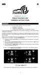
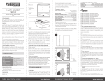
Works with:
VERA 2 / 3 / Lite
LAGOTEK
Z-Wave Motion Sensor
User Guide
DHS-ZW-SNMT-01
Table of Content
Product Overview
Z-Wave Operations
Integration with Vera2/3/Lite Home Controller
Prerequisites
Including the sensor into Vera Z-Wave Home Network
Exclusion (unpairing) of the sensor from Z-Wave home network
Inclusion (pairing) of the sensor with Z-Wave home network
Configuring the Motion Sensor
Configuring the Temperature Sensor
Calibration of the Temperature Sensor, using Temperature Offset parameter
Selecting UPnP configuration files for the Temperature Sensor
Configuring the Illumination Sensor
Selecting UPnP configuration files for the Illumination Sensor
Using Motion sensor in Vera Scenes
Creating motion detected events in Vera scenes
Using Temperature Sensor in Vera Scenes
Creating conditions in Vera scenes based on temperature readings
Using Illumination Sensor in Vera Scenes
Creating conditions in Vera scenes based on illumination readings
Changing Wakeup Interval and pulling settings for Illumination Sensor in Vera
Frequently Asked Questions
Appendix
Indication mode
2
3
4
4
5
5
5
6
7
7
7
8
8
9
9
9
10
10
10
11
11
12
13
TRADEMARKS
All trademarks and registered trademarks are the property of their respective owners or
companies.
Product of Digital Home Systems Pty Ltd
See all range of compatible devices at www.digitalhomesystems.com.au or
www.zwave.com.au
Enquiries Sales and Marketing Email: [email protected]
© 2012 Digital Home Systems Pty Ltd. All rights reserved.
2
Installation
Z-Wave Operations
1. Use a flat screwdriver at the inlets on
the sides to gently unlock the back cover.
The Z-Wave Motion Sensor can detect movement, measure light intensity and temperature and can trigger a security system.
2. Use the designated holes on the back
cover to screw mount of the Motion Sensor.
For optimal use, mount the Motion Sensor
between 1,8m and 2,4m above ground
(A rotating bracket is available to adjust the
direction the Motion Sensor is pointing to).
NOTE: Before including the product to your Z-wave network it is advised to perform
removal procedure to reset network settings.
3. Place two AA 1,5V batteries into the device.
4. Mount the Motion Sensor onto the
back cover and be sure to close it on all
sides and that the tamper gets through
the back cover of the Motion Sensor (indication mode: Tamper pressed/released).
5. After 3 seconds start up routine begins
(indication mode: Ready for learn mode).
6. After 5 more seconds (8 seconds in total)
mounting is completed. (Indication mode:
Mounting successful).
7. Motion Sensor has to start up for 10 seconds.
8. After 10 seconds the Motion Sensor is
ready for detection.
The Z-Wave Motion Sensor must be included into your Z-Wave home network before it
can send and receive Z-Wave commands. Z-Wave Motion Sensor can only communicate
to devices within the same Z-wave home network. Always follow your controller’s specific
instructions for Z-wave inclusion, exclusion, association or temperature reading.
Inclusion to Z-wave home network – general instructions
There are two ways to include node:
1. NWI mode (only include node). After applying power (by putting the batteries), the
Sensor will stay in NWI mode for 30 seconds. Use your controller to include the sensor
to the network during this time. When Z-Wave sensor is not added in network within 30
seconds, it does not function correctly.
2. Classic mode. Please press the tamper switch at the back of the device for 3-8 seconds.
After 3 seconds, the led will blink; you can now release the button. Now it's ready for learn
mode (include/exclude/association). Use your controller to include the sensor to the network during this time.
Exclusion from Z-wave home network – general instructions
1. Please press the tamper switch at the back of the device for 3-8 seconds.
2. After 3 seconds, the led will blink; you can now release the button.
3. Now it's ready for learn mode (include/exclude/association). Use your controller to
include the sensor to the network during this time.
Network Wide Inclusion
When the Z-Wave Motion Sensor is not yet included, it will automatically start NWI for 120
seconds after placing the batteries. (Indication mode: Learn in progress (add)).
Make sure your Z-Wave controller is in the correct operating mode (inclusion).
3
Include or exclude mode
Integration with Vera Home Controller
1. Make sure your Z-Wave controller is in the right operation mode (include or exclude).
2. When the Z-Wave Motion Sensor is mounted, remove it from the back cover as explained
in step one of the Mounting instructions.
3. Press and hold the tamper for 4 seconds (indication mode: Ready for learn mode). Now
release the tamper switch to start the inclusion or exclusion process (indication mode: Learn
in progress).
Indication mode
MiCasaVerde Vera2/3/Lite (refered later as Vera - some minor differences in User Interface
UI4 and UI5 explained) is a fully featured, easy to install, configure and use Home Automation controller with Z-Wave build-in interface.
More information about Vera is available at: http://wiki.micasaverde.com or
http://forum.micasaverde.com or http://www.zwave.com.au
Australian version of Vera Home Controller (921.42MHz build-in Z-Wave interface) is available at http://www.zwave.com.au
The indicator light gives various statuses of the device as follows:
Prerequisites
1. Ready for learn mode:
2. Learn in progress (add):
3. Learn in progress (remove):
4. Learn mode success:
5. Learn mode failed:
6. Tamper pressed/released:
7. Mounting successful:
indicator light blinks every second
indicator light 2 times every second.
indicator light 3 times every second.
indicator light is on for one second.
indicator light blinks 8 times rapidly.
indicator light blinks 3 times rapidly.
indicator light is on for 1 second.
Vera 2/3/Lite needs to work with Z-Wave interface in version 3.20. Please check the following options in your Vera2 Dashboard under “Z-Wave Device / Options” or Vera3 under “ZWave Settings”. Polling setting are just an example here and can be set up as you need.
If your settings are different, then change them as per above screenshot or follow the instructions on http://wiki.micasaverde.com to setup Z-Wave interface to version 3.20.
4
Including the sensor into Vera Z-Wave Home Network
NOTE:
The Z-Wave Motion Sensor must be included into your Z-Wave home network
before it can send and receive Z-Wave commands. Z-Wave Motion Sensor can only
communicate to devices within the same Z-wave home network.
Before including the product to your Z-wave network it is advised to perform Exclusion procedure to reset network settings.
Exclusion (un-pairing) of the sensor from Z-Wave home network
1.Remove (if there were any) batteries from the sensor, and install them again.
2. Press and hold a Z-Wave button on the back side of a Vera for 3 seconds. After releasing the
Z-Wave button a Z-Wave led on front panel of the Vera should blink quickly. That means that
Vera is in Z-Wave exclusion mode.
3. Please press the tamper switch at the back of the device for 3-8 seconds.
4. After 3-5 seconds, the led will blink three times; you can now release the button.
5. Exclusion should start immediately. Very quick blinking on the Z-Wave led on Vera front
panel, followed by one second long, solid light of the sensor’s led indicates successful exclusion.
6. Press and release twice a Z-Wave button on the back side of a Vera.
7. Wait till Vera finish reconfiguration of the Z-Wave interface. Progress is presented in the
top, right hand side corner of the Vera dashboard.
8. Repeat the above steps if you haven’t observed indication of a successful Exclusion, as per
step 5 above.
4. Please press the tamper switch at the back of the device for 3-8 seconds.
5. After 3-5 seconds, the led will blink three times; you can now release the button.
6. Exclusion should start immediately. Very quick blinking on the Z-Wave led on Vera front
panel, followed by 1 second long, solid light of the sensor’s led indicates successful inclusion.
7. Press and release a Z-Wave button on the back side of a Vera.
8. Wait till Vera finish reconfiguration of the Z-Wave interface. Progress is presented in the
top, right hand side corner of the Vera dashboard.
9. When Vera signals that it wait for the device to wakeup, press and keep temper button
on the device for 3-5 seconds. Once led on the Sensor blinks three times (once per second)
release the temper button.
10. Vera will now configure your sensor with standard values and create an association.
Wait about 15-30 sec for Vera to finish this step.
NOTE:
You should see by now the following screen. There should be three virtual devices.
If you see only one device “_Motion Sensor” that means Vera didn’t refreshed your
dashboard yet. Try to refresh it manually by clicking on the refresh button (see below
in red)
Inclusion (pairing) of the sensor with Z-Wave home network
NOTE:
The method described is a Classic mode inclusion. The other, more advanced method, called NWI mode, is applicable for other Z-Wave controllers and for simplicity this
method is not presented here.
1. Remove (if there were any) batteries from the sensor, and install them again.
2. Wait 2 minutes till blinking on the Sensor’s led (two blinks a second) stops.
3. Press and release a Z-Wave button on the back side of a Vera. Z-Wave led on front panel
of the Vera should blink slowly. That means that Vera is in Z-Wave inclusion mode.
11.Repeat the above steps if the inclusion was unsuccessful.
5
Configuring the Motion Sensor
NOTE:
The sensor has a few configurable parameters which determine its behaviour. The
configurable parameters related to the Motion Sensor are:
a)Mode Timeout - used in mode 2 to turn the sensor off for time specified in
this parameter in seconds, after motion detection.
b) Switch Off Time – this timeout (in seconds) will start running as soon
as Mode Timeout is finished. Motion sensor is turned on and when move
ment is detected again the Mode Timeout will start running all over again.
When Switch Off time is finished a basic off message is sent to the associated
controller (e.g. Vera) or node (e.g. light switch).
c) The Mode - The mode that is entered after detection.
Mode 1: no detection possible. Battery save mode.
Mode 2: normal operation mode: send on after detection and off
after given time no detection.
Mode 3: Z-Wave chip is always on for configuration purpose. If
mode is 0 or higher then 3, that value will be reported for
get commands, but the sensor will be run as mode 2.
b. “Data Size” – choose “1 byte hex”
c. “Desired Value” – type required -,value, e.g. 64
6. Click SAVE in Vera and wait till new settings are saved in Vera.
7. Press the temper button on the device and keep it for 3-7 seconds, then release. This is to
wake up and propagate the settings.
8. Check the configured values in the field “ConfiguredVariable” or “VaraiblesGet” fields on
“Advance Tab” in the Seetings box of the “_Motion Sensor”.
Your Motion Sensor is set up.
Example
In this example we set up the following parameters for Motion Sensor:
a.
Mode TimeOut = 1 sec
b.
Switch Off time = 15 sec
c.
Mode = 2 (normal operations)
d) Sensitivity - the sensitivity of the motion circuit. Value range is 0-127,
where 0 is least sensitive
1. Open settings box for “_Motion Sensor” in Vera dashboard. Go to “Device Options” tab.
2. Click on “Add configuration settings”. Fill out the fields:
a. “Variable” – type “2”
b. “Data Size” – choose “2 byte hex”
c. “Desired Value” – type required Mode Timeout value, e.g. 1
3.
Click on “Add configuration settings”. Fill out the fields:
a.
“Variable” – type “3”
b. “Data Size” – choose “2 byte hex”
c. “Desired Value” – type required Switch Off Time value, e.g. F
4. OPTIONAL for Mode selection. Click on “Add configuration settings”. Fill out the fields:
a. “Variable” – type “5”
b. “Data Size” – choose “1 byte hex”
c. “Desired Value” – type “2”
5. OPTIONAL for Sensitivity selection. Click on “Add configuration settings”. Fill out the
fields:
a. “Variable” – type “4”
6
Setting parameters
Configuring the Temperature Sensor
NOTE:
The sensor has a few configurable parameters which determine its behaviour.
The configurable parameter related to the Temperature Sensor is:
Temperature Offset - An offset for the temperature in degrees. Default is
zero. Change this parameter only if you need to calibrate the Temperature
Sensor.
Also, you have to change the UPnP files to enable proper integration and presentation of the Temperature Sensor in Vera. The preinstalled UPnP device for your Temperature Sensor is “TemperatureSensor”.
Calibration of the Temperature Sensor, using Temperature Offset parameter
Confirming configured parameters
1. Open settings box for “_Motion Sensor” in Vera dashboard. Go to “Advanced” tab.
2. Click on “Add configuration settings”. Fill out the fields:
a. “Variable” – type “6”
b. “Data Size” – choose “2 byte hex”
c. “Desired Value” – type required Temperature Offset value, e.g. 5
3. Click SAVE in Vera and wait till new settings are saved in Vera.
4. Press the temper button on the device and keep it for 3-7 seconds, then release. This is to
wake up and propagate the settings.
5. Check the configured values in the field “ConfiguredVariable” or “VaraiblesGet” fields on
“Advance Tab” in the Seetings box of the “_Motion Sensor”.
Selecting UPnP configuration files for the Temperature Sensor
NOTE:
Your Temperature sensor is a child device - of the parent device “_Motion Sensor”. Out
of two “_GenericIO” devices the one with the altid=e1 is your Temperature Sensor.
The altid number you can find under “Advanced” tab of the setting box.
1. Open settings box for “_GenericIO” with altid=e1 in Vera dashboard. Go to “Device Options” tab.
2. Replace the content of the following two fields with the values provided below:
device_type = urn:schemas-micasaverde-com:device:TemperatureSensor:1
device_file = D_TemperatureSensor1.xml
7
3. Click SAVE in Vera and wait till new settings are saved in Vera.
Your Temperature Sensor is set up.
You may want to change its name or assign it to room.
device_type = urn:schemas-micasaverde-com:device:LightSensor:1
device_file = D_LightSensor1.xml
3. Click SAVE in Vera and wait till new settings are saved in Vera.
4. Press the temper button on the device and keep it for 3-7 seconds, then release. This is to
wake up and propagate the settings.
Your Illumination Sensor is set up.
You may want to change its name or assign it to room.
Configuring the Illumination Sensor
NOTE:
There are no configurable parameters related to the Illumination Sensor.
You have to change the UPnP files to enable proper integration and presentation of
the Illumination Sensor in Vera. The preinstalled UPnP device for your Illumination
Sensor is “LightSensor”.
1. Open settings box for “_GenericIO” with altid=e2 in Vera dashboard. Go to “Device Options” tab.
2. Replace the content of the following two fields with the values provided below:
8
By now, all your three sensor should be set up in Vera and you should see the following
three logical devices in the Vera dashboard (See below picture).
If you still see old “_GenericIO” devices (so in total more then three) that means Vera
didn’t refreshed your dashboard yet. Try to refresh it manually by clicking on the refresh
button (see below in red)
You can test or re-configure the sensor, by setting up scenes with motion sensor as an
event and by changing the timeout settings as per above steps.
“New Scene -> Events tab -> Add Event” (Vera) or “New Scene -> Triggers” (Vera 3 /Lite UI5)
Device=Motion sensor
Type of Event= A sensor (door/windiow/motion etc.) is tripped
Name=whatever
Tripped=No
Using Temperature sensor in Vera Scenes
Using Motion sensor in Vera Scenes
NOTE:
When the Motion Sensor is tripped, it sends to Vera a tripped command and changes
its state to Tripped=1 for the duration of the Mode Timeout plus Switch Off Time
variables. After this time has expired, it sends an Untripped command to the Vera and
resets it state to Tripped=0. While the device is in a tripped state, any motion detected during Switch Off Time period resets the interval timer but doesn’t report a new
trip event to the Vera. During the wait time the Motion Sensor device in the Vera will
show Tripped=1 in the Advanced tab.
To use tripped and untripped commands in Vera you have to use them as events in
the Vera scenes.
Creating motion detected events in Vera scenes
NOTE:
The sensor sleeps for the duration of the Wake Up interval, which defaults to 1800
seconds or 30 minutes. When the interval expires, it wakes up and reports Temperature to the Vera.
To use temperature readings in Vera you have to use luup code under “Luup” tab of
your scene tool. It is strongly recommended to read instructions on luup and luup
codes in Vera scenes on http://wiki.micasaverde.com for more details.
C
Creating
ti conditions
diti
iin V
Vera scenes based
b d on temperature
t
t
readings
di
Example of luup code to stop a scene from executing if the Temperature (Temperature Sensor reading) is higher then 20.
1.
Create first scene in Vera in standard way.
2.
Set a condition to not run the scene based on the most recent temperature reading,
as per below:
New Scene -> Luup
Example
1.
Create first scene in Vera in standard way.
2.
Add action to turn on light as desired in the standard way.
3.
Set event when the unit has tripped, as per below:
“New Scene -> Events tab -> Add Event” (Vera) or “New Scene -> Triggers” (Vera 3 /Lite UI5)
Device=Motion sensor
Type of Event=A sensor (door/windiow/motion etc.) is tripped
Name=whatever
Tripped=Yes
4.
5.
6.
local lul_temp=luup.variable_get(‘urn:upnp-org:serviceId:TemperatureSensor1’, ‘CurrentTemperature’, 4)
if (tonumber(lul_temp) > 20.00) then
return false
end
Create second scene in Vera in standard way.
Add action to turn off light as desired in the standard way.
Set event when the unit has tripped, as per below:
9
In this example the Temperature Sensor has ID = 4. Replace it with your device ID
Using Illumination Sensor in Vera Scenes
NOTE:
The sensor sleeps for the duration of the Wake Up interval, which defaults to 1800
seconds or 30 minutes. When the interval expires, it wakes up and may be pulled for
current illumination level reading by Vera.
To use temperature readings in Vera you have to use luup code under “Luup” tab of
your scene tool. It is strongly recommended to read instructions on luup and luup
codes in Vera scenes on http://wiki.micasaverde.com for more details.
Creating conditions in Vera scenes based on illumination readings
Example of luup code to stop a scene from executing if the illumination (Illumination Sensor
reading) is higher then 29.
1.
Create first scene in Vera in standard way.
2.
Set a condition to not run the scene based on the most recent illumination reading,
as per below
New Scene -> Luup
3.
Click “Save Lua” and then SAVE in Vera and wait till new settings are saved.
local lul_light= luup.variable_get(‘urn:micasaverde-com:serviceId:LightSensor1’, ‘CurrentLevel’, 5)
if tonumber(lul_light) > 29 then
return false
end
In this example the Light Sensor has ID = 5. Replace it with your device ID
10
3.
Click “ Save Lua” and then SAVE in Vera and wait till new settings are saved.
Changing Wakeup Interval in Vera
NOTE:
The sensor sleeps for the duration of the Wake Up interval, which defaults to 1800
seconds or 30 minutes.
Keep in mind that them more often the device is waked up the more energy it consumes. As a result battery will run down much quicker.
Example of setting new Wakeup Interval of 300 seconds or 5 minutes
1.
Click “ Save Lua” and then SAVE in Vera and wait till new settings are saved.
“_Motion Sensor” box -> Settings
Wakeup Interval (seconds) = <new desired value>
Poll this device at most once every = <new desired value, the same as new Wakeup Interval>
2.
3.
4.
5.
6.
Click SAVE in Vera and wait till new settings are saved in Vera.
Please press the tamper switch at the back of the device for 3-8 seconds.
After 3-5 seconds, the led will blink three times; you can now release the button.
Immediately click on “Configure node right now” button on “_Motion Sensor” box /
Settings tab.
Wait till the new settings are propagated to the Sensor.
Frequently Asked Questions
Q: I can’t have my Z-Wave sensor included into my Z-Wave network, what am I doing
wrong?
A:
1. Is the controller ready to include any device into the Z-Wave network? If the con
troller is not in
Include or exclude mode, the Z-Wave sensor cannot be included or excluded.
2. The Z-Wave sensor is already included in a Z-Wave network. Exclude the Z-Wave
sensor and try to include it again.
Q: Why doesn’t the Z-Wave sensor detect any movement?
A:
1. The Z-Wave sensor isn’t included in a Z-Wave network. Include it and try it again.
2. The batteries are almost empty, try putting new ones in.
Q: The temperature report of the Z-Wave sensor is incorrect.
A:
1. The Z-Wave sensor is placed directly in the sun, which makes the temperature in
the housing of the Z-Wave sensor hotter than elsewhere in the room.
2. The calibration is not the same as your other temperature sensor; it is possible to
do a re-calibration of the temperature sensor.
Q: I have configured a value but when I request it, it is not changed?
A:
It is mandatory that the correct size is used while configure a parameter; go to the
documentation about the configuration command class to check if the right size is
used during configuration. If the wrong size is used the frame is ignored totally.
Q: I have configured a new value and when I request it the correct value is returned but the
behaviour is still the same?
A:
Some configuration parameters have limits of what they can do, go to the docu
mentation about configuration to check if the value of the configured parameter is
out off limit.
Q: When I mount the Z-Wave sensor it performs its standard mounting routine but after 8
seconds the indicator light doesn’t go on for 1 second but blinks 6 times.
A:
blinking 6 times can mean:
1. Z-Wave sensor is not included
2. Z-Wave sensor is not associated
3. Z-Wave sensor can’t reached his destination
If all three options are corrected, Z-Wave sensor is will operate correctly and can be
mounted again.
11
Appendix
Indication mode
The indicator light gives various statuses of the device as follows:
1. Ready for learn mode:
indicator light blinks every second
2. Learn in progress (add):
indicator light 2 times every second.
3. Learn in progress (remove):
indicator light 3 times every second.
4. Learn mode success:
indicator light is on for one second.
5. Learn mode failed:
indicator light blinks 8 times rapidly.
6. Tamper pressed/released:
indicator light blinks 3 times rapidly.
7. Mounting successful:
indicator light is on for 1 second.
Technical Specifications
NOTE:
This part of the Instructions contains advanced details about the Sensor and its configuration parameters and supported Z-Wave commands.
This can be used for advanced configuration and integration not only with Vera but
with other Z-Wave controllers or gateways.
Supporting Command Classes
Basic type: BASIC_TYPE_ROUTING_SLAVE
Generic type: GENERIC_TYPE_SENSOR_BINARY
Specific type: SPECIFIC_TYPE_NOT_USED
Listening: False, Z-Wave Lib: 4.51
Class: 0x30 COMMAND_CLASS_SENSOR_BINARY
Class: 0x31 COMMAND_CLASS_SENSOR_MULTILEVEL
Class: 0x60 COMMAND_CLASS_MULTI-CHANNEL_V2
Class: 0x70 COMMAND_CLASS_CONFIGURATION
Class: 0x71 COMMAND_CLASS_ALARM
Class: 0x80 COMMAND_CLASS_BATTERY
Class: 0x84 COMMAND_CLASS_WAKE_UP
Class: 0x85 COMMAND_CLASS_ASSOCIATION
Class: 0x86 COMMAND_CLASS_VERSION
Class: 0xEF COMMAND_CLASS_MARK
Class: 0x20 COMMAND_CLASS_BASIC
Class: 0x31 COMMAND_CLASS_SENSOR_MULTILEVEL
12
Not listening Routing SLAVE
This Z-Wave product will be used as routing slave. Slave nodes are nodes in a Z-Wave network that receive commands and perform actions based on the command. This device will
always be in sleep mode because it works on batteries. In sleep mode the device is not active
listening, the device will wake up according to the wakeup command class.
Include Initiator
The include initiator is used when Primary and Inclusion Controllers include nodes into the
network. When both the include initiator have been activated simultaneously the new node
will be included to the network (if the node was not included previously).
Exclude Initiator
The exclude initiator is used by Primary Controllers to exclude nodes from the network.
When the exclude initiator and a slave initiator are activated simultaneously, it will result in
the slave being excluded from the network (and reset to Node ID zero). Even if the slave was
not part of the network it will still be reset by this action.
Z-Wave compatibility
Because this is a Z-Wave device, it means it can co-operate with other Z-Wave devices of
other manufacturers. It can co-exist in a Z-Wave network existing with product from other
manufacturers.
Hops & Retries
The Z-Wave range has a range of up to 30 meters in line of sight. This signal is not limited
to the 30 meter range due to routing the Z-Wave message to other nodes in the network.
This way the range of the Z-Wave network can be expanded to 150 meters indoors (limit of
4 hops).
Class: 0x20 COMMAND_CLASS_BASIC
When a movement is detected a basic set frame with value 255 is sent to the associated
nodes. If the configured time is done with no movement is detected a basic set frame with
value 0 is sent to the associated nodes. This is the controlling role of the basic command
class.
The supporting role of the basic command class is mapped to the sensor binary command
class.
Class: 0x25 COMMAND_CLASS_SENSOR_BINARY
The Sensors Binary Command Class can be used to check if motion is detected, value 0
means that there is no motion detected and therefore a associated node is off, value 255
means that a associated node is on.
Class: 0x80 COMMAND_CLASS_BATTERY
This class is used to request and report battery levels for a given device. When battery level
is lower than 20% Z-Wave sensor will send a battery warning (value 255) after every wake up
notification. A ‘battery get’ will report the actual value even if below 20 %
4.
Size:
Param1:
Class: 0x86 COMMAND_CLASS_VERSION
This Command Class is used to obtain information about the Z-Wave sensor. The Z-Wave
library type, the Z-Wave protocol version and the application version will be reported.
Class: 0x70 COMMAND_CLASS_CONFIGURATION
Configure parameters:
0.
Not used
1.
Set to default
Description:
Set all config values to default values (factory settings). Read
more in
chapter configuration Reset.
Size:
1 byte*
Param1:
if OxFF then set to default
Param2,3,4:
not used
2.
Mode timeout
Description:
The time used in mode 2 to turn the sensor off. This
Time will start running as soon as detection is seen.
Default value: 0x0384 = 900 sec = 15 min
Size:
Param1:
Param2:
Param3,4:
3.
2 bytes (integer)*
the most significant byte of the integer
the least significant byte of the integer
not used
5.
Param2,3,4:
The mode
Description:
Default:
The mode that is entered after detection
0x02
Size:
Param1:
Param2,3:
6.
Default value:
The switch off time will start running as soon as mode timeout
is done. Motion sensor is turned on and when movement is de
tected again the mode timeout (cfg param 1) will start running
all over again. When switch off time is done a basic off message is
sent to the associated node.
0x0A8C = 2700 sec = 45 min.
Size:
Param1:
Param2:
Param3,4:
2 bytes (integer)*
the most significant byte of the integer
the least significant byte of the integer
not used
the sensitivity of the motion circuit
0x50 = 80
1 byte*
Sensitivity value between 0 and 127 (values above 127 will be
reported
as the set value but will be handled in SW as 127).
0 is least sensitive and 127 is the most sensitive.
not used
1 byte*
mode 1, 2 or 3.
Mode 1: no detection possible. Battery save mode
Mode 2: normal operation mode: send on after detection and off
after given time no detection.
Mode 3: Z-Wave chip is always on to request e.g. version or
manufacturer id. If mode is 0 or higher then 3, that value will be
reported after a get but will be handled in SW as mode 2.
not used.
The temperature offset
Description:
A offset for the temperature.
Default:
0x00
Size:
Param1,2:
Param3,4:
Switch off time
Description:
Sensitivity
Description:
Default:
2 bytes*
A signed integer to determine the offset off the temperature.
not used.
*if a size is other then given size the frame is ignored totally so configuration values are not
changed
Class: 0x31 COMMAND_CLASS_SENSOR_MULTILEVEL
Sensor_multilevel_get
The Z-Wave sensor Multilevel Command Class is used to get a report from the Z-Wave sensor.
The returned value is the measured temperature inside the housing with 2 decimals.
13
Class: 0x60 COMMAND_CLASS_MULTI_CHANNEL_V2
Request temperature
Channel 1
Note: The returned value is the measured temperature (+/- offset) inside the housing with 2
decimals.
Request light / lux
Channel 2
Note: The returned value is the measured LDR resistance in %.
Class: 0x85 COMMAND_CLASS_ASSOCIATION
The Association Command Class is used to associate other devices with the Z-Wave sensor.
The devices that are associated can be controlled on application level. The Z-Wave sensor
can be associated into a grouping. If so, the Z-Wave sensor can control another Z-Wave
device.
Number of groupings: 1
Maximum supported nodes per group: 5
Because only one group is supported grouping identifier is ignored in all cases.
Class: 0x84 COMMAND_CLASS_WAKE_UP
The Wake Up Command Class is used at battery-operated devices. This class allows the
Z-Wave sensor to wake up occasionally to notify others devices, that the Z-Wave sensor is
ready to receive commands. After receiving the commands the Z-Wave sensor will go into
sleep mode again. The wake up interval can be set using the WAKE_UP_INTERVAL_SET
command.
The default value is 0x1C20 = 7200 sec = 2 hour
The default node is 0xFF = 255 (broadcast)
It is possible to send a wake up notification on user interaction. To do this press and hold
the tamper switch for 8 seconds.
When the wake up time is set to 0 a wake up notification is never send periodically, only on
user interaction.
Class: 0x71 COMMAND_CLASS_ALARM
This command class is used to identify the state of the tamper alarm. The device will send
an unsolicited report to the controller if the status is changed, the value 0x00 will indicate
that the tamper is placed correctly on the wall. The value 0xFF will indicate a tamper alarm.
There is 1 alarm type:
3: Tamper switch
Every other alarm type that is requested will be ignored by application.
Every other alarm type that is requested will be ignored by application.
Configuration Reset
The Z-Wave sensor supports a configuration reset function. Configuration reset means
-All configuration values are defaulted.
-Wake up interval is defaulted.
This function can be activated by sending a configuration set frame:
CONFIGURATION_SET
Parameter:
0x01
Size:
0x01 (can’t be different from 1)
Value:
0xFF (can be any value except for 0x55 or 0xAA)
When the value of configuration value is requested 2 possible values can be returned
CONFIGURATION_REPORT
Parameter:
0x01
Value 0x55:
Device doesn’t have all his configuration settings anymore.
Even when a configuration parameter is changed back to the default
value
Value 0xAA:
Devices still has all his factory settings.
This are only configuration parameters, wake up interval can be changed.
Always awake mode
The always awake mode is used to request different values from the device.
The always awake mode can be activated by:
CONFIGURATION_SET
Parameter:
0x05
Size:
0x01 (can’t be different from 1)
Value:
0x03 (mode 3)
The always awake mode can be deactivated by:
CONFIGURATION_SET
Parameter:
0x05
Size:
0x01 (can’t be different from 1)
Value:
Any value except 3
A second option to deactivate mode 3 is
1. Remove batteries.
2. Wait 10 seconds.
3. Replace batteries
Note: in always awake mode the batteries will be drain very fast, we do not recommend to
use this mode.
14