1
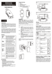
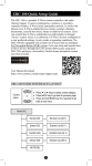
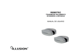
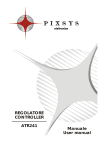
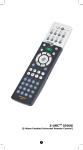
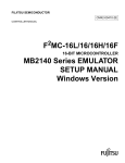
400x224mm
fold to 80 x112mm
Introduction:
Wireless Lighting Control
ZDS-200NA
Dimming Switch Module
(Dual mode)
USER MANUAL
Key Features:
Thank you for choosing the ZDS-200 (Dimming Switch Mini Module) Z-Wave
control product! ZDS-200 enabled product allows users to remotely control
lighting, home appliance, and make home control easy with low installation
and maintenance costs. You may begin with a few Z-Wave enabled devices as
well as some of our products to build up a complete home automation system.
The ZDS-200 is a Z-Wave enabled device and is fully compatible with any ZWave enabled network. It can be configured as either a "DIMMER" or a
"SWITCH" device. It allows remote Dimming or ON/OFF control of specified
lamps. Each module is designed to act as a repeater, which will re-transmit a
radio frequency (RF) signal by routing the signal around obstacles and radio
dead spots to ensure that the signal is received at its intended destination.
-
Glossary
Product Overview:
Device /
Light / Node
Z-Wave Network
Devices, lights and nodes are all terms to describe an individual ZWave device. These terms are all interchangeable when setting up
your Z-Wave network.
A collection of Z-Wave devices are controlled by primary and
secondary controllers operating on the same system. A Z-Wave
network has its own unique ID code so that controllers not in the
network cannot control the system.
Inclusion
Add a Z-Wave device to the network.
Exclusion
Delete a Z-Wave device from the network.
Network Wide
Inclusion (NWI)
Scene
A
B
C
D
E
Status LED
ON/OFF/DIMMER/PROG Push button
Z-Wave controlled outlet
AC plug
Selective switch (SWITCH or DIMMER Mode)
A
B
C
D
E
1
2. Plug the lamp into the ZDS-200 Z-Wave outlet.
Ensure that the loading is not exceeding 330 Watts Incandescent.
Lower than 330 Watts
Incandescent or
Resistive Load
3. Plug the ZDS-200 into a wall AC outlet.
8. Plug the lamp into the ZDS-200 Z-Wave outlet.
Ensure that the loading does not exceed 330 Watts Incandescent or 500
Watts Resistive Load.
9. Plug the ZDS-200 into a wall AC outlet.
10. Press the button to turn the light ON/OFF. (This button is a toggle switch press the button once to turn the light ON if the device is OFF and viceversa)
ZDS-200 can be configured as either a "DIMMER" or a "SWITCH" device, and
it will detect the operation mode using the position of the slide switch when
powering on. The ZDS-200 will stay in the selected operation mode after
inclusion process, and it will not respond to the slide switch selection after
removing and re-adding power.
If the user needs to change the operation mode, the user must first perform
an exclusion process. The user will then switch to the target operation mode
(Dimmer or Switch), and re-include the ZDS-200 afterwards.
Warning:
- SWITCH Mode is required for inductive and capacitive devices unsuitable
for dimming, (e.g. fluorescent lamps, motors etc.). The dimming function
will be disabled in this mode.
- It could damage the ZDS-200 if connected to non-dimmable load and
perform dimming function in DIMMER mode!
Dimmer (Dimming)
Switch (On/Off)
6. Unplug the ZDS-200 from wall AC outlet.
7. Switch to SWITCH mode.
SWITCH
SWITCH
DIMMER
5
6
The incandescent light plugged into the Z-Wave controlled outlet on this
module must not exceed 330 watts. DO NOT connect fluorescent light.
Plugging a non-resistive load such as fluorescent light or a device with a motor
into the Z-Wave controlled outlet may result in damage to the ZDS-200
Dimming Switch Module and will void the warranty.
ZDS-200 will not block the lower outlet when plugged into upper outlet of a
duplex wall receptacle. Possible configurations are illustrated below.
Grounded AC outlet VS
2-pins AC power plug
Grounded AC outlet VS
3-pins AC power plug
Basic Operation
ZDS-200 can be configured as either a "DIMMER" or a "SWITCH" device, and
it will detect the operation mode using the position of the slide switch when
powering on.
Warning:
- SWITCH Mode is required for inductive and capacitive devices unsuitable
for dimming, (e.g. fluorescent lamps, motors etc.). The dimming function
will be disabled in this mode.
- It could damage the ZDS-200 if connected to non-dimmable load and
perform dimming function in DIMMER mode!
The connected device can be turned ON in two ways:
1. Manual control with the push button on the ZDS-200.
2. Z-Wave remote controller.
Installed at
upper AC outlet
BW8330
(Z-URCTM 550)
Push button
BW8380
(ZRC-100)
Manual ON/OFF/DIM function
Installed at
lower AC outlet
2
Z-Wave setup and operations
4. Press the button to turn the light ON/OFF. (This button is a toggle switch press the button once to turn the light ON if the device is OFF and viceversa)
5. Pressing and holding the button will control the brightness. Release the
button when the desired brightness is attained. (This is also a toggle
function - press and hold the button to increase the brightness. To
decrease the brightness, press and hold the button again.)
Installation and Warning
1. Switch to DIMMER mode.
DIMMER
Association
Network Wide Inclusion (NWI) enables both end-user friendly, Plug
and Play like Z-Wave network installation as well as professional
installation scenario where the inclusion process in terms of time
will be reduced significantly. NWI is a feature supported by a new
frame type named Explorer which enables the Z-Wave protocol to
implement Adaptive Source Routing.
Association is used to organize nodes into different groups allowing
the device to identify the nodes with a group identifier. These
groups can also be copied to other devices.
A scene is a collection of Z-Wave devices configured to turn to a
specific level, setting, mode, or perform an operation. Scenes are
usually activated by a controller, timed event, or a specific condition.
Supports Dual mode (DIMMER and SWITCH)
Remote ON/OFF/DIM control via the Z-Wave controller
Manual ON/OFF/DIM control with the front panel push button
Support Scene control
Support Association Group and Auto Report switch status
Supports Network Wide Inclusion (NWI) and Explore Frames
High output power in DIMMER and SWITCH mode
Over temperature protection
Grounded 3-wire power connection for safety
Does not block lower outlet when plugged into upper outlet of a duplex wall
receptacle
Z-Wave Remote Control
Include or exclude the ZDS-200 from the existing Z-Wave home control
network with your primary controller.
- Refer to your primary controller instructions to process the inclusion /
exclusion setup procedure.
- When prompted by your primary controller, triple click the PROG button
within 1 second.
(The unit will enter classical inclusion/exclusion first, then jump to NWI, and
after 5 seconds, it will finally exit NWI mode automatically if there is no
inclusion/exclusion request.)
- The primary controller should indicate that the action was successful. If the
controller indicates the action was unsuccessful, please repeat the
procedure.
- Once the unit is part of the network, the same basic procedure is used to
add the same unit to a group or scene. Refer to the primary controller's
instructions for more details for adding/removing the unit to/from the
scene/association.
All configuration parameter values will keep no changes after excluding the
unit from the network, except for the parameter number 1 and Association
information.
Z-Wave Configuration Parameters
Different user has different preferred settings of their thermostat, you may use
the below configuration parameters to change settings of corresponding
functionality.
Definitions:
Activate/Deactivate units to ALLON/OFF
Parameter No.: 1 (0x01)
Parameter value: 0 (0x00) - ALL ON is not active, ALL OFF is not active
1 (0x01) - ALL ON is not active, ALL OFF active
2 (0x02) - ALL ON is active, ALL OFF is not active
255 (0xFF) - ALL ON is active, ALL OFF is active
Default Value:
255 (0xFF)
Dimmer Mode:
Supported
Switch Mode:
Supported
7
3
Switch returns to the last position saved before
power failure
Parameter No.: 5 (0x05)
Parameter value: 0 (0x00) - Switch does not save the state after power
failure, device returns to "off" position
1 (0x01) - Switch saves its state before power failure
Default Value:
1 (0x01)
Supported
Dimmer Mode:
Supported
Switch Mode:
Definitions:
Double click option (set to max. brightness)
Definitions:
Parameter No.: 13 (0x0D)
Parameter value: 0 (0x00) - Double click function disabled
1 (0x01) - Double click function enabled
Default Value:
1 (0x01)
Supported
Dimmer Mode:
Switch Mode:
Time of moving the Dimmer from 0% to max.
dimming values.
(The ZDS-200 will implement the dimming duration if
received this parameter value from controller/gateway.
Otherwise, the ZDS-200 will implement the local
parameter value)
Parameter No.: 17 (0x11)
Parameter value: Dimmer Mode
From 0 to 5 seconds
Step size = 1 second
Default Value:
3 (0x03)
Supported
Dimmer Mode:
Switch Mode:
Definitions:
8
4
Maximum Dimmer level control
(refer to Figure 1 and Notes)
Parameter No.: 18 (0x12)
Parameter value: 2 (0x02) to 99 (0x63) %
Default Value:
99 (0x63)
Supported
Dimmer Mode:
Switch Mode:
Definitions:
Definitions:
Minimum Dimmer level control
(refer to Figure 1 and Notes)
[Below is the recommendation for different loads.
AC motors:
Parameter no. 18 max. = 99%
Parameter no. 19 min. >= 60%
Fluorescent lamps, fluorescent tubes, non-dimmable
LED:
Parameter no. 18 max. = 99%
Parameter no. 19 min. = 98%
Remark:
1) The maximum level must not be lower than the
minimum level.
2) Parameter no. 17 MUST set to 0]
Parameter No.: 19 (0x13)
Parameter value: 1 (0x01) to 98 (0x62) %
Default Value:
13 (0x0D)
Supported
Dimmer Mode:
Switch Mode:
-
9
340x256mm
fold to 80 x112mm
Brightness level (lux)
ge
ran
le
ca 9%)
s
9
ng
mi 1 to
dim m
le e fro
b
a
ail ng
av (ra
m
ara
ete
o.
rn
n.
Mi
lev
el
m
ara
r
ete
8)
.1
no
(p
n.
Lower limit (e.g. 30%)
)
19
Association group_1
for Auto report to gateway
50%
Upper limit (e.g. 85%)
Z-Wave Gateway
(Node ID-A)
Association group_2
for dimmer and switch mode
ZDS-200 also can act as a "Switch" with parameter no. 17, 18 and 19. The
"Switch" function is required for inductive and capacitive devices unsuitable
for dimming (e.g. fluorescent lamps, motors etc.).
Example
30%
Support for Association Groups
85% 99%
Z-Wave dimming commands
(0x00 = Off, 0xFF = On, 0x01 = 1% to 0x63 = 99%)
Figure 1
Notes:
In order to avoid flickering and to support non-dimmable devices, the ZDS-200
provides parameter no. 18 and 19 (max. and min. dimmer level control). If
there is flickering, the user can re-configure the max. and min. level for the
dimmer to skip the flickering at min. or max. level.
Example Procedure:
Step-1: Set the maximum value to 99 (99%) - parameter no. 18.
Step-2: Set the minimum value to 1 (1%) - parameter no. 19.
Step-3: Go back to normal operation mode for dimming.
10
Technical Specifications
ZDS-200 supports 2 association groups. A maximum of 1+4 node ID's (nonmulti-channel devices) can be assigned to these association groups.
Association group_1:
- Association group_1 is used to report status changes such as AUTO report
to gateway. (Max. 1 node ID can be assigned to this association group)
ZDS-200 will trigger AUTO report function if the Dimmer or Switch status had
been changed.
Association group_2:
- Dimmer mode: After receiving a dimming command from a local switch or
gateway (e.g. 50%), the ZDS-200 will automatically send out a related basic
set command (e.g. 50%) to its associated group.
- Switch mode: After receiving a basic set command from a local switch or
gateway, On (0xFF) or Off (0x00), the ZDS-200 will automatically send out a
related basic set command, On (0xFF) or Off (0x00) to its associated group.
(Max. 4 node ID's can be assigned to this association group)
BW8130US (ZDS-200NA)
RF frequency
908.42MHz
Input voltage / frequency
120Vac / 60Hz
RF operating distance
up to 30m (line of sight between the Wireless Controller
and the closest Z-Wave receiver module at open area)
DIMMER:
Max Incandescent load 330W 2.75A
SWITCH:
Max Incandescent Load 330W 2.75A
Max Resistive Load 500W 4.16A
Detected internal temperature, and cut off output once
Over Temperature protection OTP triggered (Remark: Under over loading or
temperature situation, it will fail to start up).
Dimension (L x W x T)
Weight
100 x 54 x 39mm
125g
Storage Temperature
-10~60 oC
o
Operation Temperature
0~40 C
Relative Humidity:
5~95%
Environment
Indoor use only
Note:Specifications subject to change without notice due to continuing product
improvement.
15
UL Listed:
This power unit is intended to be correctly orientated in a vertical or floor
mount position.
The four possible responses are:
- It will respond to ALL ON and the ALL OFF commands (default).
- It will not respond to ALL ON and ALL OFF commands.
- It will respond to the ALL OFF command but will not respond to the ALL ON
command.
- It will respond to the ALL ON command but will not respond to the ALL OFF
command.
No. of Node ID in Association Group_1: 1 max. (AUTO report)
No. of Node ID in Association Group_2: 4 max.
User can assign 0 to 4 node ID's (from node ID-B to ID-E) to its association
group_2.
Function example: ZDS-200 will send out a control command to Association
group_2 devices when ZDS-200 status had been changed.
Device load turned on
Device load turned off
Device load dimming
Device not currently paired
into a Z-Wave network
LED Indication Status
LED turns on.
LED turns off.
LED keep in previous stage.
LED will continuously flash two times per second.
If the device already existing in the network, LED will flash
slowly for 2 seconds, and then return to previous ON or
Learning / NWI mode:
OFF stage.
Triple click on PROG If the device does not exist in the network, LED will keep
button
flash slowly and waiting for Network Wide Inclusion (NWI).
(The device will exit NWI mode automatically after 5
seconds)
Receive command / Send LED will flash 2 times, and then return to previous ON or
command or data
OFF stage.
Configure command error
LED will rapidly flash 6 times, and then return to previous
ON or OFF stage.
ALL ON/OFF functions
Depending upon your primary controller, the ZDS-200 can be set to respond to
ALL ON and ALL OFF commands up to four different ways. Some controllers
may not be able to change the response from its default setting. Please refer
to your controller's instructions manual for information on whether or not it
supports the configuration function and if so, how to change these settings.
FCC Information
FCC ID : 2ADPEDA011
This device complies with Part 15 of the FCC Rules. Operation is subject to
the following two conditions:
(1) this device may not cause harmful interference, and
(2) this device must accept any interference received, including interference
that may cause undesired operation.
Note:
This equipment has been tested and found to comply with the limits for a Class
B digital device, pursuant to Part 15 of the FCC Rules. These limits are
designed to provide reasonable protection against harmful interference in a
residential installation. This equipment generates, uses and can radiate radio
frequency energy and, if not installed and used in accordance with the
instructions, may cause harmful interference to radio communications.
However, there is no guarantee that interference will not occur in a particular
installation. If this equipment does cause harmful interference to radio or
television reception, which can be determined by turning the equipment off and
on, the user is encouraged to try to correct the interference by one or more of
the following measures:
- Reorient or relocate the receiving antenna.
- Increase the separation between the equipment and receiver.
- Connect the equipment into an outlet on a circuit different from that to which
the receiver is connected.
- Consult the dealer or an experienced radio/TV technician for help.
Notice:
Changes or modifications to this unit not expressly approved by the party
responsible for compliance could void the user authority to operate the
equipment.
- To avoid the risk of electric shock, the input prong comes with a round
grounding plug. The switch module can only be plugged in to the power
inlet with the grounding plug. Please contact a qualified electrician to
replace the power inlet if it has no grounding inlet. Do not change the plug
of this unit in any way.
- Do not modify the unit in any way.
- Risk of fire.
- Risk of electrical shock.
- Risk of burns.
- This unit never got qualified certificate to supply power for medical
instrument or any life support equipment.
- Do not dispose of electrical appliances and unsorted municipal waste, use
separate collection facilities. Contact your local government for information
regarding the collection systems available.
- There are no user serviceable parts in this unit.
16
17
Warnings
All Configuration Parameter values and Association information will be
restored to factory default settings and excluded from the network.
Setup Key
LED Indication Status
1
Press and keep holding the PROG
button for no less than 10 seconds.
- LED state will toggle for first 5 seconds
of being pressed.
- LED state will toggle again after the
remaining 5 seconds.
2
Release the PROG button then triple
click the PROG button within 2
seconds of step 1.
- LED will stay in previous ON or OFF
stage.
Step
Wireless Information
Wireless range:
This device has an open-air line-of-sight transmission distance of 30m, which
is compliant with the Z-Wave standards. Performance can vary depending on
the type of obstacles, such as walls and furniture, between the Z-Wave
devices. Every Z-Wave device set up in your network will act as a signal
repeater, allowing them to talk to each other and to find alternate routes in the
case of reception dead spots caused by these obstacles.
Radio Frequency Limitations:
1. Each wall or object (i.e.: refrigerator, bookshelf, large TV, etc) can reduce
the maximum range by up to 20-30%. Plasterboard and wooden walls will
have less effect on the signal than concrete, brick, or tile.
2. Wall mounted Z-Wave devices will also suffer a loss of range if they are
housed in metal junction boxes, which could reduce the range by up to 2030%.
Maintenance
12
IC information
IC : 12524A-DA011
This device complies with Industry Canada licence-exempt RSS standard(s).
Operation is subject to the following two conditions:
(1) this device may not cause interference, and
(2) this device must accept any interference, including interference that may
cause undesired operation of the device.
This device complies with RSS-310 of Industry Canada. Operation is subject
to the condition that this device does not cause harmful interference
Restoring Factory Defaults
LED Indication Status
Operations
Z-Wave devices (Node ID)
(ID-B)
(ID-C)
(ID-D)
(ID-E)
Please refer to your controller's instructions for information on whether or not
it supports the Association function.
11
Certifications
Model no.
Max. output power
User can adjust the brightness level upwards/downwards from 50% until the
flicking point is distinguished.
Step-5: Set the maximum value to 85 (e.g. 85%) for parameter no. 18 (Max).
Step-6: Set the minimum value to 30 (e.g. 30%) for parameter no. 19 (Min).
Step-7: Keep this setting as the new default. This way, user will avoid
flickering as a result from low or high outputs from this dimmer.
e
lev
0
Operation diagram for Association Groups:
Brightness level
l (p
Mi
Step-4: User is required to distinguish the flickering points by adjusting the
dimming level on controller, such as gateway or ZRC-100.
1. Do not expose your unit to dust, strong sunlight, humidity, high
temperatures or mechanical shocks.
2. Do not use corrosive or abrasive cleansers on your unit.
3. Keep the unit dust free by wiping it with a soft, dry cloth.
4. Do not disassemble your unit; it contains no user-serviceable parts.
14
13
Warranty
ONE-YEAR LIMITED WARRANTY: Remotec warrants this product to be free
from defects in materials and workmanship under normal use and service for
a period of one year from the original date of purchase from the distributor or
dealer.
REMOTEC shall not be liable for:
- Damages caused by defective devices for indirect, incidental, special,
consequential or punitive damages, including, inter alia, loss of profits,
savings, data, loss of benefits, claims by third parties and any property
damage or personal injuries arising from or related to the use of the device.
- Service trips to provide instruction on product use.
- Shipping costs for replacement products.
This warranty is limited to the repair or replacement of this product only, if the
purchase date cannot be substantiated, the warranty period will begin on the
date of manufacture as indicated on this product. All warranty claims must be
made to Remotec appointed distributors or dealers during the applicable
warranty period. This warranty gives you specific legal right and you may also
have other rights which vary in each country. Please contact Customer
Service at:
Remotec Technology Limited
E-mail: [email protected]
http://www.remotec.com.hk
Printed in China
18
F820-8130-0000
19