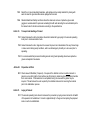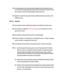
1
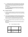
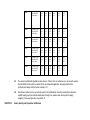
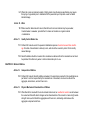
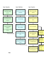
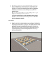
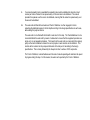
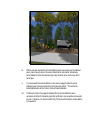
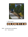
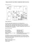
OPERATIONAL PROCEDURES
for
CEMENT & RENOLITH ® POLYMER STABILISED ROAD PAVEMENT
CHAPTER I General
Article 1.
Domain of Application:
This book is for the execution and delivery of cement and Renolith chemical additive to construct polymer
stabilised road pavements.
It contains the technical details and materials needed for execution.
1.1
Cement stabilised pavements for roads, airfields, rail embankments and hardstand storage areas has now
been generally accepted world-wide. While various cement materials have been used, such as hydrated
lime and fly ash, Portland has been generally accepted by governmental and private contracting agencies
as being the preferred active binder for soil stabilisation, due to its ability to flocculate the very fine particles
of silty soils and highly plastic soils.
1.2
The use of polymer-creating additives that further enhance the tensile strength, flexibility and resistance to
moisture permeation in stabilised pavement has been growing steadily across the world. Not only are these
technical benefits accruing from the use of these chemical additives with cement, but also the substantial
economic and environmental cost savings that go with the predominant elimination of imported quarried
hard rock aggregates, and the much reduced environmental cost thereof, especially in the European Union,
where vastly greater emphasis has been placed on environmental issues and their resolution.
1.3
The most immediate effect of the use of cement-polymer pavement stabilisation, is the virtual elimination of
the need for various graded aggregates in road pavement construction.
Article 2.
2.1
Objective
To improve both the workability of the cement stabilisation process for road construction; to reduce the
likelihood of any cement stabilised pavement failure due to shrinkage of the cement on setting; and to give
greater tensile strength and flexibility to the pavement.
2.2
Article 3.
(i)
The standard international road flexible cement stabilised pavement design as undertaken shall be
retained, as if the additive product has not been included, and shall depend on the road usage, respective
axle loadings, terrain, soil type (especially regarding high plasticity soils) and whether the road is to be
sealed or unsealed; and
(ii)
Road lateral and longitudinal subsoil drainage and table drains shall be provided to protect the
earthworks and pavement material, including the mix so formed by the inclusion of the Renolith additive
product into the pavement material mix.
Defining Types of In-Situ material
3.1
Renolith polymer-creating additive is designed to work in conjunction with cement with a wide range of soil
and sub-grade types to make a strong and flexible pavement for roads and to enhance quality and durability
of the final pavement
3.2
The volume of cement and the diluted application rate of Renolith are determined by various factors that
must first be established to enable proper design of the road. These factors include the plasticity of the road
sub-base, the type of sub-base soil, the CBR (Californian Bearing Ratio), projected traffic including
maximum axle load weight, volume of projected traffic and the required lifetime of the road pavement.
3.3
The volume of cement appropriate to the different soil types and plasticity index is shown in the guide line in
the following Table 1.
Note: These are typical indicated values only, which must be verified or amended by the manufacturer or
consulting engineer.
Table 1
Soil Types & Cement Required for Stabilization
Plasticity Index
( from
Atterberg Limits )
PI
Typical Soil, Sub-base, or Subgrade Description
> 24
Highly Plastic / expansive CLAYS , often black
6.0 – 7.0
Highly Plastic / expansive CLAYS , often black or red,
brown, grey mottled
5.0 – 6.0
20 - 24
Nominal
Cement
Ranges ( % )
3.4
16 - 20
Moderately Plastic / expansive CLAYS and SILTY
CLAYS
Often black/grey, red, brown or grey mottled
4.0 -5.0
10 - 16
Moderately Plastic CLAYS, SILTY CLAYS and
SANDY CLAYS, often red or brown / grey mottled
3.0 – 5.0
6 - 10
Low Plasticity CLAYEY SILTS and CLAYEY SANDS
Often red, brown or grey mottled – often friable
3.0 – 4.0
<6
Low Plasticity CLAYEY SANDS often red, brown, grey
White – often friable
3.0
River SANDS or SILTY SANDS, fine and rounded,
Uniform grading, white or grey
3.0
Beach or River SANDS, course and angular, white,
Orange or grey
2.0 – 3.0
The application rate of Renolith appropriate to the soil type and plasticity index is indicated in Table 2.
Table 2 - Material Estimates - Renolith Additives for Road Construction
Pavement
Cement Content
Renolith/Water
2%
3%
4%
5%
6%
7%
120
Cement (kg/m2)
Renolith (l/m2)
Water (litres)
4.8
0.12
1.2
7.2
0.18
1.8
9.6
0.24
2.4
12.0
0.30
3.0
14.4
0.36
3.6
16.8
0.42
4.2
150
Cement (kg/m2)
Renolith (l/m2)
Water (litres)
6.0
0.15
1.5
9.0
0.23
2.3
12.0
0.30
3.0
15.0
0.38
3.8
18.0
0.45
4.5
21.0
0.53
5.3
180
Cement (kg/m2)
Renolith (l/m2)
Water (litres)
7.2
0.18
1.8
10.8
0.27
14.4
0.36
2.7
3.6
18.0
0.45
4.5
21.6
0.54
5.4
25.2
0.63
6.3
Depth (mm)
CHAPTER II
200
Cement (kg/m2)
Renolith (l/m2)
Water (litres)
8.0
0.20
2.0
12.0
0.30
3.0
16.0
0.40
4.0
20.0
0.50
5.0
24.0
0.60
6.0
28.0
0.70
7.0
225
Cement (kg/m2)
Renolith (l/m2)
Water (litres)
9.0
0.23
2.3
13.5
0.34
3.4
18.0
0.45
4.5
22.5
0.56
5.6
27.0
0.68
6.8
31.5
0.79
7.9
250
Cement (kg/m2)
Renolith (l/m2)
Water (litres)
10.0
0.25
2.5
15.0
0.38
3.8
20.0
0.50
5.0
25.0
0.63
6.3
30.0
0.75
7.5
35.0
0.88
8.8
275
Cement (kg/m2)
Renolith (l/m2)
Water (litres)
11.0
0.28
2.8
16.5
0.42
4.2
22.0
0.55
5.5
27.5
0.69
6.9
33.0
0.83
8.3
38.5
0.97
9.7
300
Cement (kg/m2)
Renolith (l/m2)
Water (litres)
12.0
0.30
3.0
18.0
0.45
4.5
24.0
0.60
6.0
30.0
0.75
7.5
36.0
0.90
9.0
42.0
1.05
10.5
350
Cement (kg/m2)
Renolith (l/m2)
Water (litres)
14.0
0.35
3.5
21.0
0.52
5.2
28.0
0.70
7.0
35.0
0.87
8.7
42.0
1.05
10.5
49.0
1.22
12.2
3.5
The cement and Renolith application rates shown in Tables 1 & 2 are indicative only, and in each case the
Renolith distributor should be consulted for the recommended application rates appropriate to the
particular road design and the factors outlined in 2.2
3.6
Renolith and cement can be successfully used for the rehabilitation of existing road surfaces where the
asphalt topping layer has suffered deterioration through time, weather and use beyond the design
capability of the wearing surface. See Article 17.
Nature, Quality and Preparation of Materials
Article 4.
Aggregates
4.1 The construction of cement stabilised road pavements has been accepted and used world-wide for many
years
as this technology enables considerable savings in material costs, environmental costs and time. Cement has
the effect of flocculating the fine grains of silty soils and plastic clays, allowing better compaction and reducing
the capillary effect of moisture intrusion, which causes clays to expand.
4.2 Cement stabilised road pavement eliminates the need to bring in expensive crushed aggregates to form
road sub-base, because the chemical reaction of Renolith, cement and water with soil creates a bound material
with greater tensile strength and resistance to moisture penetration than conventional road base and sub-base
layers comprised of graduated aggregates.
4.3 The use of Renolith additives to cement, water and in-situ soil material has increasingly gained favour since
it was first developed and used in Germany more than 20 years ago. It enhances the tensile strength and
flexibility of the cement-stabilised pavement layer, providing greater resilience to surface deflection caused by
traffic, and even greater resistance to moisture penetration, because the voids between material particles are
eliminated, giving even greater resistance to moisture penetration. Apart from the greater residual strength of the
pavement, the effect of freeze-thaw heave is substantially reduced and in many cases eliminated.
4.4 Accordingly, it is not necessary to specify grades of aggregate to be used in a cement-Renolith stabilised
road pavement, as the import to site of expensive aggregates is largely avoided.
Article 5.
5.1
Active Binder
Standard Portland GP cement is used as the active binder. Quick setting cement should not be used.
Article 6.
Renolith Additives
6.1 Renolith used as an additive to cement and in situ soil material comprises hydrated calcium chloride
and acrylic copolymer latex in a solution of water, and should comply with ISO 9001:2008
Article 7.
Tacking Coat
7.1
Where the finished cement-polymer stabilised pavement is to be topped with either Hot Asphalt Mix
(HAM) or chip seal to provide a wearing surface, the stabilised pavement should be coated with an
appropriate liquid bitumen emulsion.
(e.g. Colas R175 or R250) to provide a tacking coat for the bitumen.
7.2
A first coat of bitumen emulsion is applied by hand-held wand sprayer attached by hose to the
discharge pump on the bitumen tanker, or by direct spray from the bitumen tanker. Care must be
taken to ensure that the entire pavement area is liberally coated and allowed to dry. Drying time will
vary depending on air temperature, but the water content of the emulsion evaporates leaving a
coating of charged particles of bitumen which turns black when total water content evaporation has
occurred.
7.3
The second coat of bitumen emulsion can be applied immediately after the first coat has
evaporated and become touch dry.
7.4
If a hot mix asphalt wearing coat is to be used, application can be undertaken at any time after the
second tack coat has dried, and standard spreading and roller compaction procedures followed.
7.5
If a wearing coat of 10mm hard aggregate is to be used, spreading by truck can commence
immediately after the second tack coat is applied. This is undertaken by a tipping truck following
immediately behind the bitumen emulsion spray and either mechanically or hand spreading of the
aggregate to ensure complete coverage of the tack-coated stabilised pavement surface.
7.6
Where a heavier wearing layer is required by the design specifications, the loose surface aggregate
should be removed by brushing, and a third coat of bitumen emulsion applied, followed by a second
layer of 10mm hard aggregate applied.
Article 8.
High Plasticity In Situ Soil Material
8.1 Where highly plastic clays are encountered in the sub-base layer, a stratum of low plasticity material
should be added to a depth of 100mm over the clay. This can consist of laterite, crushed limestone,
sand or fly ash.
Article 9.
Fibres
9.1 Where the in situ soil material consists of highly plastic clays the design specification may require
the laying of a geotextile prior to stabilisation of the pavement layer to provide a wick for added
lateral drainage.
Article 10. Water
10.1 Water used for admixture with cement, Renolith and in situ soil material may be pure water,
brackish water or seawater, provided that it is clean and contains no organic material
contamination.
Article 11.
Quality Control Before Use.
11.1 Portland GP cement used in the pavement stabilisation process should not exceed three months
age from date of manufacture to delivery to site, and should be covered to protect from humidity
caused damage.
11.2 Renolith additive should be in sealed drum containers as delivered from the manufacturer and must
be protected from dilution by water or other contaminants prior to use.
CHAPTER III Method of Mixture
Article 12.
Composition of Mixture
12.1 Portland GP cement, Renolith additive and water in the proportions required for the specifications as
per tables 1 and 2 or as specified by the manufacturer or consultant, are mixed on site with the
aggregate, natural stone, and soil fines in situ.
Article 13.
Physical Mechanical Characteristics of Mixture
13.1 When Renolith is mixed with the in-situ material and cement, an exothermic reaction occurs between
the cement and Renolith which changes certain characteristics of the cement to create a high tensile
strength mixture, which binds the aggregates and fines in situ, eliminating voids between the
aggregate components and fines.
13.2 The mixture remains in a workable condition for a period of time to enable compaction, trimming and
rolling to provide a finished pavement surface of the specified depth. Optimum performance is
gained by compaction immediately after completion of the stabilisation mixture.
Article 14.
14.1
Equipment
Equipment required (all in good working condition) typically will include:
(i)
Road Grader (Cat 12 equivalent or larger) with Rippers and Tines;
(ii)
Stabilisation Machine (pass width generally 2.0 to 2.7 metres);
(iii)
Bulk cement spreading truck(s) or flattop truck(s) for bagged cement;
(iv)
Water Trucks (2 minimum)
(v)
Water Truck with horizontal rear mounted spray-bar with all fully operational flow rated
nozzles;
(vi)
Article 15.
Rollers:-
sheep-foot or equivalent with tractor for pulling or self-propelled
-
steel drum, self-propelled (preferably 10-15 tonne)
-
Multi pneumatic tire self-propelled
(vii)
Farm tractor with power take-off and heavy duty rotary hoe. (e.g. Bomag)
(viii)
Road broom or equivalent.
Making the Mixture of Renolith Additive and Water
15.1 When mixing, the concentrated Renolith liquid should always be added to the water.
15.2 The tanker truck/water cart should be filled with water, leaving sufficient capacity for the Renolith to
be added.
15.3 The volume of Renolith required by the specifications (e.g. 3 litres concentrate to 10 litres water)
should then be pumped from the delivery container to the tanker truck/water cart.
15.4 The pump delivery hose should be introduced into the top tanker truck delivery port before starting
the pump.
15.5 Moving the end of the delivery hose within the tank will assist agitation with thorough mixing of the
solution.
15.6 Care should be taken to ensure that the correct volume of Renolith is mixed with water in the tank.
Article 16.
Regulating the Site for Mixing Renolith and Water
16.1 No special mixing site need be provided. This procedure can be done at any convenient place on or
adjacent to the stabilisation area where the tanker truck/water cart can be positioned conveniently
beside the bulk polymer supply.
Article 17.
Control of Mixing in the Stabilisation Process
17.1 Thorough mixing of cement, Renolith and the in-situ material is critical to the success of the
stabilisation process.
17.2 The Stabilisation Procedure as set out in Article 26, should be carefully followed to ensure the
complete mixture within the stabilised pavement for optimum performance.
CHAPTER IV
Method of Operation
Article 18.
Transport and Handling of Renolith
18.1
Renolith is supplied in concentrated form in 200 litre drums on pallets, or 1000 litre pallecons, which
may be safely transported on conventional trucks.
18.2
Renolith is not flammable, toxic or hazardous, and does not require special handling conditions.
18.3
Renolith is not environmentally hazardous, and spillage can be readily dealt with by hosing with
water to clean the ground surface where spillage has occurred.
18.4
Standard Health and Safety conditions should be observed, and use of protective gloves and
goggles is recommended for personnel unloading Renolith and decanting the concentrated liquid to
the tanker trucks for dilution and mixture according to the specifications.
Article 19.
Transport and Handling of Cement
19.1 Cement delivered to site by bulk tanker should be transferred by pumping to the cement spreading
truck prior to commencement of work.
19.2 Cement delivered to site in bags must be covered to prevent air contamination from any broken bags
or loose cement during windy conditions, and to avoid damage by humidity or a rain event prior to
spreading.
19.3 It is recommended that personnel handling cement during hand spreading should wear protective
gloves and aspirator face masks.
Article 20.
Preparation of Work
20.1 Check area with Stabilizer (if required). One pass of the stabilizer can be run without cement or
polymer over a short length of road surface (say 50 metres) to determine how the stabilizer handles
the in-situ material. If the material is too compacted, tinning the area with the grader may be
required. This will reduce the work required by the stabilizer and assist in loosening the material
prior to the stabilization process.
Article 21.
Laying of Cement
21.1 The cement spreading truck should commence the procedure by laying cement across the full width
of the pavement to be stabilised. Cement is applied directly to the ground comprising the proposed
road or road to be rehabilitated.
21.2 If cement is delivered to site in bags, bags should be dumped directly from the delivery truck on to
the road surface at the spacing prescribed in the specifications and spread with a spreader bar or by
hand using rakes to achieve the specified application rate per square metre.
21.3 Application of cement to the paving area should be immediately followed by commencement of the
stabilisation process.
Article 22.
Compaction
22.1 Initial compaction should immediately follow completion of the stabilisation and mixing process.
22.2 Initial compaction is undertaken by not less than two passes of a 10 tonne pad foot roller or four
passes of a 5 tonne roller.
22.3 Initial compaction is followed by trimming to finish level and fall by grader.
22.4 Secondary compaction is then undertaken by non-vibrating flat drum roller – minimum of two passes
by a ten tonne roller or four passes by a five tonne roller.
22.5 Final compaction is then performed by multi pneumatic tyre roller in a minimum of two passes.
22.6
(i)
As with most polymer forming compounds, a low level of heat is generated in the chemical
reaction’s occurrence and accordingly, limited time is available to complete the mixing after
the product has been incorporated. Hence, the length of the section under construction
should be limited to the time available, the mixing, rolling and trimming equipment availability
and expertise available for the operation of such equipment;
(ii)
Additional water may be required during mixing, to maintain OMC and accordingly a stand-by
water truck loaded with water only should be available;
(iii) Spray-bars used for depositing the Renolith diluted liquid into the pavement material mix shall
have their nozzles directly pointing into the construction area and not be able to spray outside
this area (i.e. not to waste product);
(iv) Depending on the capacity of the stabiliser being used, and if pavement depths greater than
250mm are required, stabilisation may be undertaken in layers of a maximum depth of 250mm
each.
Article 23.
Surface Treatment of Finished Layer
23.1 If the road pavement surface is not required to be finished with a bitumen wearing layer, it should be
treated with an aggregate pressed into the surface in accordance with Article 26.3, I, ii and iii.
23.2 If the road pavement surface is required to be finished with a bitumen wearing layer, it should be
treated as provided in Article 7.
Article 24.
Control of Operating Method
24.1 The General Foreman is responsible to ensure that all of the required resources and personnel are
available prior to commencing any road stabilization activities. The General Foreman is also
responsible to determine the areas to be completed and to provide detail of cement and Renolith
quantities required and the rates of application to the Senior Foreman in charge of the crew. The
General Foreman is responsible to communicate any problems or issues to the Manager/Consulting
Engineer for resolution.
24.2 The Senior Foreman is responsible for the coordination of equipment and personnel to undertake
the stabilization works. The Senior Foreman is responsible to ensure that the instructions from the
General Foreman are followed by the crew. The Senior Foreman is responsible to communicate any
problems or issues to the General Foreman for resolution.
24.3 The Senior Foreman is responsible to supervise the crew in the completion of the works and to
ensure that the work is completed following all safety requirements and in line with the instructions
given. The Foreman is responsible to communicate any problems or issues to the Senior Foreman
for resolution.
Article 25.
Flow Chart of Operations
Stage 1: Preparation
Stage 2: Stabilization
Stage 3: Completion
Ensure road profile is to design.
Correct areas needing
attention.
Fill Water Cart #1 with Water
and Renolith
Water Cart to give light
watering
How is Water Content?
Wet area with watercart if
necessary.
Cement Spreading
Compact with Smooth Drum
Roller
Stabilization with Watercart /
Tractor / Stabilizer
Final Trim with grader
How is the compactionof the
material - too tight for
stabilizer?
Tyne the area with the grader if
required.
Compaction with Sheepfoot
Roller
Initial Trim with grader to
reshape and remove excess
material
Notes:
Water Cart to give light
watering
Final finish roll with
Smooth Drum Roller
Prior to Wearing Coat
Layer
Spread 75mm Neutral material
as the wear course
Two Tack Coats of
Bitumen Emulsion
before Wearing Coat
Layer
Compact with Smooth Drum
Roller to embed 75mm material
75% into pavement
Spread 10-15mm
crushed stone wearing
layer
Or
Hot Mix Asphalt
1.
a)
b)
c)
Assess the previous day’s work to fine tune the crew work procedure.
Assess effectiveness of traffic control, traffic movement, etc. during the stabilization process.
Discuss job with crew to identify and address any problems they may have.
a)
Pavement Finish for heavy duty mine and forestry roads: Application of a wearing coat layer
of 75mm ᴓ crushed hard stone, embedded 75% into pavement surface.
Pavement Finish for light to medium traffic public and private roads: Application of two coats
of Bitumen Emulsion and 10-15 mmᴓ crushed hard stone; or
One coat of Bitumen Emulsion tacking coat followed by application of Hot Mix Asphalt (HMA)
2.
b)
c)
Article 26. Procedures
26.1 Preparation
i.
Use Grader to profile surface of road to be stabilized (if required).
In areas where the road has lost shape through erosion, the road surface needs to be
shaped to the desired final profile prior to any stabilization works commencing. This work
should be done well in advance of the stabilization works. If necessary, tine the area to be
stabilised with the grader to break up the surface layer and facilitate more efficient
performance of the stabiliser.
ii.
Water the area (if required).
The work area material will be checked for Optimum Moisture Content (day prior to
stabilization or on the morning of starting in that area) and if required the water cart will spray
the area with water to raise the moisture content of the material to assist in achieving the
Optimum Moisture Content (OMC) of 5% for later compaction.
iii.
In cases of Low Moisture Content (if required), the water cart should pass over the area of low
moisture, with water only, thereby cutting the material and introducing additional moisture.
This will raise the moisture content to get it closer to Optimum Moisture Content (OMC) of 5%
in preparation for stabilization and compaction.
iv.
26.2
Where the design specifications for a road require the finished level of the new pavement to
be reduced in height, the top layer of in-situ material should be excavated and removed to
stockpile for re-use. The depth of this material removal should equate to the specified depth
of stabilised pavement determined in accordance with the specifications and the factors
mentioned in Article 3.
The excess sub-base material should then be excavated to a depth equivalent to the required
height reduction in the finished pavement level, and removed.
After removal of the excess material, the top layer material previously removed to stockpile
should then be replaced in-situ and compacted with a sheep-foot roller as specified in Article
22.2 before commencement of stabilisation.
Stabilization
i.
Spread the cement (either by mechanical spreader or manually over the area to be stabilized at the
required dosage as provided in Article 21. (e.g. 20kg /m2). At this application rate and with each bag
weighing 20kg - there needs to be a bag placed at each square metre of road surface. Use a
spreader frame to position the bags of cement accurately (see diagram below). After placement,
cutting and emptying the bags, a spreader can be dragged to spread the cement evenly, or
alternatively hand spread by rake.
ii.
If a cement spreading truck is available the spreading rate must be calibrated to allow the correct
volume per metre of cement to be spread evenly on the road area to be stabilised. The cement
spreader then passes over the area to be stabilised, ensuring that the cement is spread evenly over
the area to be stabilised.
iii..
The water-cart with Renolith and water and Tractor / Stabilizer are then engaged in train to
undertake the stabilisation pass to the full depth according to the design specifications in each case,
while adding the polymer solution.
The water-cart is to be filled with the Renolith / water mix for this step. The Tractor/stabiliser is to be
connected behind the water-cart by means of a draw-bar to ensure that the equipment operates as a
single unit, at a set separation distance. The hoses from the water cart are connected to the delivery
pump on the tractor/stabiliser to deliver the correct polymer / water solution via the stabilizer. This
solution will be metered via the pump and delivered at the rate per m2 according to the design
specifications. This is closely followed by the sheep-foot roller to achieve 103% compaction.
The Tractor / Stabilizer, material hardness and the rate of cement spreading will determine the speed
of progress during this step. For this reason, the water cart is pushed by the Tractor / Stabilizer.
iv.
With the water cart disconnected, the tractor/stabiliser makes a second pass over the stabilised
area to ensure thorough mixing of the cement, Renolith and in-situ material. Alternatively a
second stabiliser or tractor-mounted heavy duty rotary hoe/mixer can be used to carry out this
second pass.
v.
It is recommended that a second stabiliser or rotary hoe be engaged to make this second
stabilisation pass to ensure complete mixing of the pavement material. **That will free the
tractor/stabiliser/water cart train is free to continue forward stabilisation.
vii
The Sheep-foot roller is the engaged immediately after the second stabilisation pass in
accordance with Article 22, followed by grader trim and flat drum roller compaction and pneumatic
tire roller. Compaction is to commence within thirty (30) minutes after completion of water addition
to the pavement.
viii.
26.2
Compaction achieved, as determined by tests of the in-situ material shall be not less than 98%
standard of the maximum dry density.
Application Rates
Application rates for cement and Renolith shall be determined on site for the equipment available from
application rate tables provided with product or as specified by the manufacturer or Consulting Engineer.
Physical application rates will be determined for speed of application of the cement or Renolith, outlet
rates or spray nozzle ratings and for pavement/earthworks depths under construction. This will be
determined as a part of the stabilisation activity by the Consulting Engineer or on site by the Senior
Foreman following appropriate training.
26.3
Completion
i.
Initial grade
The grader completes the initial grade to bring the road back to the design levels and designed road
shape as the polymer increases the volume of the mix. Only use experienced grader operators. Any
excess material may need to be loaded out for use in other areas.
ii.
Surface gravel course: If a gravel wearing course is required by the specifications, a tipping dump
truck with a tail gate can be used to add a top course of neutral 10mm gravel prior to final
compaction. This top course will provide a wearing surface to the stabilized pavement. See Note 2
to Article 25. Some final trim grading may be required also.
iii.
Final compaction using a non-vibrating smooth drum roller used to push the wearing course into the
pavement material.
iv.
Equipment Train in Operation
Grader tines
Road surface
Step 1.
Water to
obtain OMC
Step 2.
Cement
Spreading
Step 3.
Stabiliser linked to
Polymer/water tanker
Step 4.
8.
CHAPTER V
Technical Quality Conditions of the Completed Stabilised Layer
Article 27.
Finished Layer Characteristics
Sheepfoot
Roller compact
Step 5.
Grader
Trim
Step 6.
Flat Drum
Roller
Step 7.
Multi Pneumatic
Tire Roller
Step
27.1
Curing of the cement/Renolith polymer stabilised pavement begins when the materials are
mixed by the stabiliser, which creates an exothermic reaction. Curing will continue over the
following 28 hours by which time the pavement will have achieved full curing.
27.2
The finally rolled, smooth finished pavement will have cured sufficiently after two hours, to
allow monitored, slow traffic to access the pavement.
Article 28.
Geometrical Elements and Tolerances
Stabilised pavements must be completed with a maximum tolerance of -/+ 10%
CHAPTER VI
Delivery of Works
Article 29.
Reception of Determined Phases
Article 30.
Preliminary Reception
Article 31.
Final Reception
APPENDICES
I
Use of Bitumen Emulsion on Finished Cement-Polymer Pavement
II
Schellenberg Test
III
Normative References