1
Interfaces of the Device
4
Interfaces of the Device
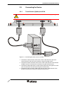
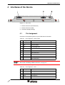
Figure 4-1
Rear view
1. Female Connector (Touch Screen)
2. Female Connector (VGA)
3. Connector (Supply Voltage)
4.1
Pin Assignment
Connector in the operating device: 9 pin D-SUB female connector
Table 4-1
Pin assignment - touch screen
Pin
Designation
Function
1
-
Not Connected
2
RD
Received Data
3
TD
Transmitted Data
4
-
Not Connected
5
GND
Ground
6
-
Not Connected
7
-
Not Connected
8
-
Not Connected
9
-
Not Connected
The D-SUB connector strips must be shielded sufficiently.
See chapter “Shielding D-SUB Connectors“ on page 4-2.
Connector in the operating device: 15 pin D-SUB female connector
Table 4-2
Pin assignment - VGA
Pin
Designation
Function
1
Red
Analog Red
2
Green
Analog Green
3
Blue
Analog Blue
4
nc
Not Connected
4-1