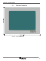
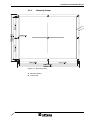
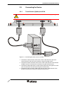
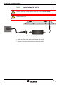
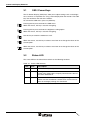
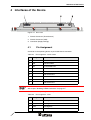
1
User Manual
TesiMon Touch Monitor TM1200
Part Number:
80 860.584
Version:
1
Date:
15 June 2004
Valid for:
TM1200
Version
1
Date
15 June 2004
Modifications
First Edition
This manual, including all illustrations contained herein, is copyright protected. Use of this manual by any third
party in departure from the copyright provision is forbidden. No part of this manual may be reproduced, translated or electronically or photographically archived or altered without the express written consent from Sütron
electronic GmbH. Violations shall be cause for damage liability.
Sütron electronic reserves the right to make any changes that contribute to technical improvement.
Overall Table of Contents
Overall Table of Contents
1
Important Notes ....................................................................................................... 1-1
1.1
2
1.1.1
General Symbols ................................................................................. 1-1
1.1.2
Specific Symbols ................................................................................. 1-1
1.2
Safety Notes ............................................................................................. 1-2
1.3
Intended Use............................................................................................. 1-2
1.4
Target Group............................................................................................. 1-2
Installation and Commissioning ............................................................................... 2-1
2.1
Unpacking the Device ............................................................................... 2-1
2.2
Mounting the Device ................................................................................. 2-1
2.2.1
Front Panel Dimensions ...................................................................... 2-2
2.2.2
Mounting Cutout .................................................................................. 2-3
2.2.3
Side View, Mounting Depth ................................................................. 2-4
2.3
3
5
Connecting the Device.............................................................................. 2-5
2.3.1
Touch Screen (Option) and VGA ......................................................... 2-5
2.3.2
Supply Voltage 100 - 240 V ................................................................. 2-6
2.4
Switching the Device on............................................................................ 2-7
2.5
Identification.............................................................................................. 2-7
Control and Display Elements ................................................................................. 3-1
3.1
OSD / Power Keys .................................................................................... 3-2
3.2
Status-LED................................................................................................ 3-2
3.3
Touch Screen............................................................................................ 3-3
3.3.1
Installing the Touch Screen Driver....................................................... 3-3
3.3.2
Calibrating the Touch Screen .............................................................. 3-3
3.4
4
Symbols .................................................................................................... 1-1
Display ...................................................................................................... 3-3
Interfaces of the Device ........................................................................................... 4-1
4.1
Pin Assignment ......................................................................................... 4-1
4.2
Shielding D-SUB Connectors.................................................................... 4-2
Maintenance and Servicing ..................................................................................... 5-1
5.1
Front Panel ............................................................................................... 5-1
6
Technical Data......................................................................................................... 6-1
A
Index ........................................................................................................................A-1
i
Overall Table of Contents
ii
Important Notes
1
Important Notes
1.1
Symbols
The symbols in this manual are used to draw your attention on notes and dangers.
1.1.1
General Symbols
Danger
This symbol is used to refer to instructions which, if ignored or not carefully followed
could result in personal injury.
Note
This symbol indicates application tips or supplementary notes.
Reference to source of information
This symbol refers to detailed sources of information on the current topic.
1.1.2
Specific Symbols
The following symbols indicate specific dangers which could result in damage to
equipment or personal injury or even up to the death of the operator.
Danger - Electric Shock
Danger - Corrosive
Danger - Toxic
Danger - Explosive
Danger - Fire
Danger - Infrared Light
Danger - Electrostatic Charge
1-1
Important Notes
1.2
Safety Notes
–
Read this manual carefully before using the operating device. Keep this manual
in a place where it is always accessible to all users.
–
Proper transportation, handling and storage, placement and installation of this
product are prerequisites for its subsequent flawless and safe operation.
–
This user manual contains the most important information for the safe operation
of the device.
–
The user manual, in particular the safety notes, must be observed by all personnel working with the device.
–
Observe the accident prevention rules and regulations that apply to the operating
site.
–
Installation and operation must only be carried out by qualified and trained personnel.
1.3
Intended Use
–
The device is designed for use in the industry.
–
The device is state-of-the art and has been built to the latest standard safety requirements. However, dangerous situations or damage to the machine itself or
other property can arise from the use of this device.
–
The device fulfills the requirements of the EMC directives and harmonized European standards. Any modifications to the system can influence the EMC behavior.
1.4
Target Group
All configuration, programming, installation, commissioning, operating and maintenance work in connection with the automation system must be performed by trained
personnel only (e.g. qualified electricians, electrical engineers, etc.).
The configuration and programming personnel must be familiar with the safety concepts of automation technology.
The operating personnel must have been trained in handling the controller and be
familiar with the operating instructions.
The installation, commissioning and maintenance personnel must have an education
which entitles them to work on automation systems.
1-2
Installation and Commissioning
2
Installation and Commissioning
2.1
Unpacking the Device
Unpack all parts carefully and check the contents for any visible damage in transit.
Also check whether the shipment matches the specifications on your delivery note.
If you notice damages in transit or discrepancies, please contact our sales department immediately.
2.2
Mounting the Device
When installing the operating device, keep a minimum clearance of 30 mm (1.181")
around the operating device to ensure adequate air circulation.
When the operating device is installed horizontally, please note that additional sources of heat beneath the operating device may result in heat accumulation.
Make sure to allow sufficient heat dissipation!
Comply with the allowable temperature range listed in the technical data for the use
of the operating device!
To maintain the specified degree of protection, make sure the seal is evenly seated
on the installation surface and the hexagon nuts are tightened uniformly.
Ensure that the maximum torque of 1.2 Nm is not exceeded.
The operating device can be easily and quickly mounted from the rear of the operating device. This is particularly recommended for mounting in switchboards with a
plate thickness of approx. 1 mm to 8 mm (0.039" to 0.315").
1. Insert the operating device from the front through the mounting cutout.
2. Fasten the operating device using hexagon nuts.
2-1
Installation and Commissioning
2-2
2.2.1
Front Panel Dimensions
Figure 2-1
Front panel dimensions
Installation and Commissioning
2.2.2
Mounting Cutout
Figure 2-2
Mounting cutout
A Mounting Cutout
B Front Panel
2-3
Installation and Commissioning
2-4
2.2.3
Side View, Mounting Depth
Figure 2-3
Side view and mounting depth for the standard device
1
Front Panel
2
Circumferential Seal
3
Press-in Threaded Bolt M4 x 18 mm (0.709")
4
Mounting Surface Thickness 1 mm to 8 mm (0.039" to 0.315")
5
Spring Lock Washer B4 DIN 127 Form B (not supplied)
6
Nut M4 DIN 934 (not supplied)
Installation and Commissioning
2.3
Connecting the Device
2.3.1
Touch Screen (Option) and VGA
Make sure that your PC and monitor are disconnected from the supply voltage.
Figure 2-4
Connecting the touch screen and VGA
1. Connect the male connector of the touch screen cable with the 9-pin touch
screen interface and fasten the connector using the knurled screws.
2. Connect the female connector of the touch screen cable with the serial interface
(COM) of your PC and fasten the connector using the knurled screws.
3. Connect the VGA cable with the 15-pin female connector of the graphics card of
your PC and fasten the connector using the knurled screws.
4. Connect the other end of the VGA cable with the 15-pin VGA interface of the
monitor and fasten the connector using the knurled screws.
2-5
Installation and Commissioning
2.3.2
Supply Voltage 100 - 240 V
Hazardous voltages can exist inside electrical installations that can pose a danger to
humans. Coming in contact with live parts may result in electric shock!
Use a properly grounded power cable. The power cable must be approved by the
country where used.
Figure 2-5
Connecting the supply voltage
Do the following to connect the device to the supply voltage:
1. Plug the power cable into the connector on the device.
2. Connect the power cable with the mains power supply.
2-6
Installation and Commissioning
2.4
Switching the Device on
After applying the supply voltage, the monitor displays the message "NO SIGNAL INPUT" (status-LED flashes) or the monitor is inactive (status-LED is off).
1. If the monitor is not active, turn it on.
2. Switch the PC on.
The status LED is now active. If the status-LED flashes or if the monitor displays the
message "NO SIGNAL INPUT", check whether the VGA cable is correctly connected
and the PC is switched on.
2.5
Identification
The nameplate on the back of the device allows you to identify the device. This is
where you find the serial number of the monitor.
2-7
Installation and Commissioning
2-8
Control and Display Elements
3
Control and Display Elements
A number of operating and display elements are located on the side of the monitor.
Figure 3-1
Operating elements
1. Status-LED
2. Key "Up"
3. Key "Down"
4. On/Off Switch
5. Key +
6. Key -
3-1
Control and Display Elements
3.1
OSD / Power Keys
The On Screen Display (OSD) keys allow you to adjust settings such as the brightness, contrast, H-/V-position etc. using a menu displayed on the monitor. The OSD
keys are located on the side of the monitor.
To activate the OSD menu, press any OSD key.
Pressing this key once activates the OSD menu.
Within the menus, this key is used for navigating.
Pressing this key once activates the brightness setting option.
Within the menus, this key is used for navigating.
Use this key to switch the monitor on or off.
Within the menus, use this key to select a menu item or to change the values of the
current option.
Within the menus, use this key to select a menu item or to change the values of the
current option.
3.2
Status-LED
The status-LED on the side of the monitor has the following functions:
Table 3-1
3-2
Status-LED functions
Color
State
Description
Green
On
Monitor is Ready for Operation
Green
Flashing
No Signal
Check if the VGA Cable is Properly Connected or if the PC
has been Switched on.
Off
Monitor is Switched off or has no Supply Voltage.
Make sure that the Monitor is Switched on and that the Cables for the Supply Voltage are Connected.
Control and Display Elements
3.3
Touch Screen
The device is equipped with a resistive touch screen. You operate the device using
this touch screen.
3.3.1
Installing the Touch Screen Driver
1. Insert the driver CD into the CD-ROM drive.
2. If the driver CD does not start automatically, carry out steps 3 - 5. Otherwise continue with step 6.
3. Select the "Run" command from the "Start" menu.
4. Select "Browse" and select the EloCD.exe file from the driver CD by selecting
"Open".
5. Press OK to start the driver CD.
6. Select "Install Driver For This Computer".
7. Select "Install Serial Driver" to start the installation.
8. In the dialog that appears, select "Next" to proceed with the installation.
9. Accept the license agreement by choosing "Yes".
10. Select the serial port to which you connected the monitor and select "Next".
11. Select "Finish" to complete the installation.
The PC reboots.
3.3.2
Calibrating the Touch Screen
After installing the touch screen driver you need to calibrate the touch screen.
1. From the "Start" menu, select "Settings" and then "Control Panel".
2. Double-tap "Elo Touchscreen".
3. In the "General" tab, tap "Align...".
4. Calibrate the touch screen by tapping the marked spots one by one.
When finished, you have 30 seconds to test your calibration.
5. Select "Yes" if you are satisfied with your calibration. Otherwise select "No" to restart the calibration process.
3.4
Display
Danger - Toxic!
If the display is damaged, avoid touching, swallowing or breathing in the liquids or
gases which may leak out!
Danger - Corrosive!
If the display is damaged, avoid touching, swallowing or breathing in the liquids or
gases which may leak out!
3-3
Control and Display Elements
Your graphics card must support one of the display modes specified in the table.
Table 3-2
3-4
Display modes
Resolution
Type
Monitor Frequency (Hz)
640 x 350
VGA
70
640 x 350
VGA
85
720 x 400
VGA
70
720 x 400
VGA
85
640 x 480
VGA
60
640 x 480
VESA72
72
640 x 480
VESA75
75
640 x 480
VESA85
85
800 x 600
SVGA
56
800 x 600
SVGA
60
800 x 600
VESA72
72
800 x 600
VESA75
75
800 x 600
SVGA
85
Interfaces of the Device
4
Interfaces of the Device
Figure 4-1
Rear view
1. Female Connector (Touch Screen)
2. Female Connector (VGA)
3. Connector (Supply Voltage)
4.1
Pin Assignment
Connector in the operating device: 9 pin D-SUB female connector
Table 4-1
Pin assignment - touch screen
Pin
Designation
Function
1
-
Not Connected
2
RD
Received Data
3
TD
Transmitted Data
4
-
Not Connected
5
GND
Ground
6
-
Not Connected
7
-
Not Connected
8
-
Not Connected
9
-
Not Connected
The D-SUB connector strips must be shielded sufficiently.
See chapter “Shielding D-SUB Connectors“ on page 4-2.
Connector in the operating device: 15 pin D-SUB female connector
Table 4-2
Pin assignment - VGA
Pin
Designation
Function
1
Red
Analog Red
2
Green
Analog Green
3
Blue
Analog Blue
4
nc
Not Connected
4-1
Interfaces of the Device
Table 4-2
Pin assignment - VGA
Pin
Designation
Function
5
GND
Ground
6
GND
Ground
7
GND
Ground
8
GND
Ground
9
VGA 5V
VCC, Fused
10
GND
Ground
11
nc
Not Connected
12
VGA SDA
DDC Data
13
CRTHS
Analog HSYNC
14
CRTVS
Analog VSYNC
15
VGA SCL
DDC Clock
4.2
Shielding D-SUB Connectors
You must shield D-SUB connectors as follows:
Figure 4-2
Shielding D-SUB connectors
1
D-SUB connector
2
Shield
3
Cable clip
4
Cable
The shield must be folded back into a flat position over the cable sheath.
When fastening the cable with the cable clip, as much of the shielding as possible
must be in contact with the housing and sufficient strain relieve must be ensured.
4-2
Maintenance and Servicing
5
Maintenance and Servicing
5.1
Front Panel
You should use a damp cloth only to remove any dirt from the panel.
5-1
Maintenance and Servicing
5-2
Technical Data
6
Technical Data
Display
Type
TFT (Color)
Resolution
Max. 800 x 600 Pixels
Colors
16.7 Million
Contrast Ratio
250:1
Brightness
200 cd/m²
Response Time
50 ms
Display Area (H x W)
184.5 mm x 246 mm (7.264" x 9.685")
Touch Screen
Type
Resistive
Electrical Data
Supply Voltage
100 V - 240 V AC via Mains Adapter
Power Consumption
3.5 A (without Mains Adapter)
Connection System
D-SUB Female and Male Connector Strips, 9 Pin and 15 Pin
Low-Voltage Male Connector and Low-Voltage Female Connector (Outside Diameter 5.5 mm (0.217"), Inside Diameter 2.1 mm (0.083"))
Environmental Conditions
Operation
0 °C to 50 °C (32 °F to 122 °F)
Storage, Transportation
-20 °C to +60 °C (-4 °F to +140 °F)
Relative Air Humidity for Operation and
Storage
5% to 90%, Non-Condensing
Standards and Guidelines
Interference Immunity
EN 50082 Part 1
Emitted Interference
EN 50081 Part 1
6-1
Technical Data
Standards and Guidelines
Low-Voltage Directive
73/23/EEC
Electromagnetic Compatibility
89/336/EEC
Safety Requirements for Information Technology Equipment
EN 60950
Enclosure and Front Panel
Enclosure
Sheet Steel
Front Panel
Aluminum, Varnished
270 mm x 340 mm x 4 mm (H x B x T), (10.63" x 13.386" x
0.157")
Seal
Circumferential Rubber Seal on the Rear
Mounting Cutout
245 mm x 315 mm (H x W), (9.646" x 12.402")
Mounting Depth
Approx. 38.5 mm (1.516")
Degree of Protection
At the Front: IP65
Rear: IP20
Total Weight
Approx. 2.2 kg
6-2
A Index
C
VGA .......................................................... 4-1
Connecting........................................................ 2-5
S
D
Identification...................................................... 2-7
Intended use ..................................................... 1-2
Safety notes ...................................................... 1-2
Servicing ........................................................... 5-1
Standards.......................................................... 6-1
Status-LED........................................................ 3-2
Supply voltage 100 - 240 V ............................... 2-6
Switching on...................................................... 2-7
Symbols
General ..................................................... 1-1
Specific ..................................................... 1-1
K
T
Keys .................................................................. 3-2
Target group...................................................... 1-2
Technical data................................................... 6-1
Touch screen ........................................... 2-5, 3-3
Dimensions
Cutout ....................................................... 2-3
Front panel................................................ 2-2
Display .............................................................. 3-3
I
M
Maintenance ..................................................... 5-1
Mounting ........................................................... 2-1
P
Pin assignment
Touch screen ............................................ 4-1
U
Unpacking ......................................................... 2-1
V
VGA................................................................... 2-5
A-1
A-2
Sütron electronic GmbH
Kurze Straße 29
D-70794 Filderstadt
Phone: 0049 711 / 77098-0
Fax:
0049 711 / 77098-60
E-mail: [email protected]
Internet: www.suetron.com