1
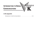
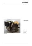
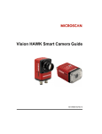
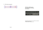
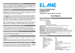
KMC Series User Manual All rights reserved. All other brand names and trademarks are the registered property of their respective owners. Specification subject to change without notice. KMC User Manual KMC0116/KMC0108/KMC0104 KMC0116 Remote/KMC0108 Remote/KMC0104 Remote KDP01/KDU01 User Manual Version 0.8.2 2007-03-28 1 Package Content Any one of KMC0116/KMC0108/KMC0104/KMC0116 Remote/ KMC0108 Remote/KMC0104 Remote contains the following items : y Main switch 1 pcs. y Power Adaptor 1 pcs. y CAT5 cable 1 pcs. y User manual 1 pcs. y Firmware upgrade Cable 1 pcs. 2 Introduction The KMC series products deliver a host of new features and latest technologies, making it another standout in the single console CAT5 KVM switches. KMC0116/KMC0108/KMC0104 access and control up to 16 computers through 1 set of keyboard, mouse and monitor console from up to 500 feet away via the CAT5 cable. The flash upgrade feature allows you to update software through a standard RS-232 serial port. OSD, Hotkey and Push button are provided for convenient computer selection and system maintenance. KDP01 is the computer end dongle with PS/2 interface. KDU01 is the computer end dongle with USB interface, The line of KMC Remote KVM switches support the remote console. 3 System Requirement 3.1 Console 3.1.1 A VGA monitor may compatible with the highest resolution that you are using on any computer s connected to the main switch.. Page 2 KMC User Manual 3.2 4 KMC0116/KMC0108/KMC0104 (w/ and w/o remote) Front View 1 2 3 4 5 6 7 8 9 10 5 3.1.2 Mouse and Keyboard with PS2 interface Computer 3.2.1 With HDB-15 Video port 3.2.2 6-pin Mini-DIN type PS2 mouse and keyboard port, or USB type mouse and keyboard port. Computer Port 1 to 4/8/16 selected LED : Light on to indicate the selection of corresponding connected computer Computer Port 1 to 4/8/16 Online LED : Light on to indicate the power on status of corresponding connected computer Computer Port 1 to 4/8/16 selection button: push and release the button to select a PC Power LED Link LED: light on when the remote console is linked. Console LED: light on when the remote console is selected. Console selection button: push and release button to select between local console and remote console. Firmware Upgrade Connector Firmware upgrade slide switch: Set to BOOT enable the firmware upgrade function. Normally it should be set to OFF. Reset button: push the button to restart the KVM switch KMC0116/KMC0108/KMC0104 (w/ and w/o remote) Rear View Page 3 KMC User Manual 1. 2. 3. 4. 5. 6. 7. 6 DC Adaptor port Remote Console port: RJ45, Console VGA port: HDB-15 female Console PS2 type mouse port Console PS2 type keyboard port Computer port 1 to 4/8/16: RJ45 Default Password Switch: When set to ON, the administrator password is reset to default factory password. Normally it should be set to OFF. KDP01 Top View 1. Link LED: light on when is connected to KMC main switch 2. Power LED: light on when get power from computer 3. RJ45 port: Plug a Cat5 Cable into this port, plug the other end of this cable into a computer port in the rear panel of a KMC main switch 4. VGA connector: Plug into the computer Video HDB-15 port 5. mouse connector: plug into the computer PS2 mouse Page 4 KMC User Manual port 6. keyboard connector: plug into the computer PS2 keyboard port 7 KDU01 Top View 1. Link LED: light on when is connected to KMC main switch 2. Power LED: light on when get power from computer 3. RJ45 port: Plug a Cat5 Cable into this port, plug the other end of this cable into a computer port in the rear panel of a KMC main switch 4. VGA connector: Plug into the computer Video HDB-15 port 5. Mouse connector: plug into the computer USB keyboard & mouse port 8 Installation Description Refer to installation diagram, to install the system in the following sequence: 1 Connect a PS2 type mouse, a PS2 type keyboard, and a VGA type monitor to the KMC main switch; then power on the monitor. 2 Plug in power adaptor, the power LED will light on. 3 For each computer/ sever that connected to the KMC main switch: 3.1 Connect the computer with KDP01 or KDU01 depend on the keyboard/ mouse interface. 3.2 Connect the KDP01 or KDU01 to the KMC main switch using Cat5 cable. Page 5 KMC User Manual 4 5 9 3.3 Power on the computer This step could be skipped if your KMC main switch does not support remote console function. Connect remote mouse, remote keyboard, remote VGA type monitor, remote sever, and KMX0102 to the remote console port of KMC Remote main switch. (See KMX0102 user manual for details) A Login OSD will be in the middle of the screen when the main switch is power on. The user need to input the name and password, the default username is ‘admin’, and default password is [enter], i.e., hit [enter] key after typing ‘admin’ into the username form. Installation Diagram Page 6 KMC User Manual Page 7 KMC User Manual 10 Operation In normal operation, 10.1 Firmware Upgrade Slide Switch should be set to OFF. 10.2 Console selection button should be set to OFF for local console, and the console LED will NOT light on. 10.3 Follow the power on sequence in installation description section. 10.4 User can manipulate KMC0116/0108/0104 (w/ and w/o remote) via button, slide switch, hotkey or OSD operation. 10.5 Refer to KMC0116/0108/0104 (w/ and w/o remote) front and rear view section for button and switch operation. 11 Hotkey Operation 11.1 The default Hot-key command sets are listed in below table. Command Key Sequence Description Function Activate or enter [ctrl],[ctrl] – Enter OSD mode OSD mode Exit OSD mode [ctrl],[ctrl],[Enter] – Quit OSD mode Port Switching [ctrl],[ctrl],[n],[enter] – Switch to computer setting port n. n = 1~16/8/4. Enter Auto Scan mode [ctrl],[ctrl],[‘S’ or ‘s’] Toggle Beeper setting Toggle Hot-key Head setting [ctrl],[ctrl],[‘B’ or ‘b’] [ctrl],[ctrl],[‘H’ or ‘h’] – Start auto-scan. Type ‘Esc’ or ‘Space’ will stop the scan – Toggle beeper setting – Toggle hot-key head to [scroll lock], [Scroll lock]. 11.2 The alternative Hot-key command sets are listed in below table. Command Key Sequence Description Function Activate or enter [scroll lock],[scroll lock] – Enter OSD mode OSD mode Page 8 KMC User Manual Exit OSD mode Port Switching setting Enter Auto Scan mode [scroll lock],[scroll lock],[Enter] [scroll lock],[scroll lock],[n],[enter] [scroll lock],[scroll lock],[‘S’ or ‘s’] Toggle Beeper setting Toggle Hot-key head setting [scroll lock],[scroll lock],[‘B’ or ‘b’] [scroll lock],[scroll lock], [‘H’ or ‘h’] – Quit OSD window – Switch to port n. n = 1~16/8/4. – start auto-scan. Type ‘Esc’ or ‘Space’ key will stop the scan – Toggle beeper setti – Toggle hot-key head to [ctrl], [ctrl]. 12 OSD Operation There are two levels of users on OSD operation: administrator and user. Only administrator can manipulate administrator operation via admin menu. This section only describes user OSD operation. The OSD window can only support keyboard manipulation, do not support any mouse operation. 12.1 Normally in OSD operation, ESC key means quit without execution, Enter key means select and execution. 12.1.1 After getting into OSD mode, user can see a list of ports that the logon user is allowed to access. User can use up and down arrow key, or page up and page down key to move cursor bar among the port list. 12.2 During the port list screen, user can hit the following key 12.2.1 F1: to user menu. Within user menu, user can set his preference of operation and view the station/dongle information. 12.2.2 F2: to Administration menu. See Administrator Operation Section for more details. 12.2.3 F5: to start auto scan 12.2.4 F10: to log out 12.2.5 ESC: to quit OSD 12.2.6 Up and down arrow key to move cursor bar 12.2.7 Enter: to select the port where cursor located and exit OSD Page 9 KMC User Manual 13 Administrator Operation In Admin menu, there are items can be invoked: 13.1 Set Station Name: max 16 characters 13.2 Set Port Name: max 16 characters 13.3 Set Server Name: max 16 characters 13.4 Add User: max 8 accounts, exclude built-in admin account. Max 16 characters for user name and password 13.5 Delete User 13.6 Set User Access Right: grant access right to the ports of computer 13.7 Firmware Upgrade: to set the station to get into firmware upgrade mode. 14 Sun Keyboard Emulation PC Keyboard Sun Keyboard PC Keyboard Sun Keyboard [ctrl],[z] Help [ctrl],[8] Copy [ctrl],[1] Stop [ctrl],[2] Props [ctrl],[9] [ctrl],[0] Paste Cut [ctrl],[5] Find Left-Window Left-meta [ctrl],[6] Again [ctrl],[7] Undo Right-Window Application Right-meta Compose 15 Specification: Product Specifications Online LED - Red Selected LED - Green I/O port select button Power LED Console LED Link LED Front Panel Console select button F/W upgrade port F/W upgrade slide KMC0116R KMC0108R KMC0104R 16 8 4 16 8 4 16 8 4 1 Red LED, Power Indicator 1 Green LED, Console Indicator 1 Red/Green LED, Remote Console Link Status 1 Push Button 1 RJ-11, Firmware upgradeable via this port 1 slide switch, Off: normal, Boot: restore F/W Page 10 KMC User Manual switch Reset switch Power supply Remote console port Default password Switch Local Console: Back Panel Monitor Keyboard Mouse I/O ports – RJ45, to computers Video Resolution Video DDC2B and EDID Cable material Cable transmission distance Dimension (W*D*H) mm Weight Housing Operation and storage parameters Operation temperature Storage temperature Humidity Reset system DC 5V, 2A RJ-45, to KMX0102, remote Console switch. 1 slide switch, Off: normal, On: restore to default password 1 VGA HDB-15 pin female 1 PS/2 mini-DIN female 1 PS/2 mini-DIN female 16 8 4 Up to 1600 x 1200@60Hz in 60 meters/200 feet Up to 1280 x 1024@60Hz in 150 meters/500 feet Real time supported CAT5/5E/5+/6 up to 150 meters/500 feet 265x145x42 265X145X2 265X145X28. 8.5 5 1200 g 1050g 1010g Metal 32 to 104 deg. F (0~40 deg. C) -4 to 104 deg. F (-20~60 deg. C) 0-80% non-condensing relative humidity 16 CAT5 cable pin assignment Page 11 part no: PB1-01C108-000