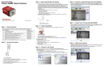
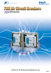
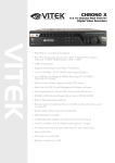
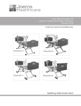
1
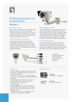
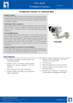
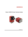
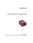
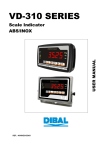
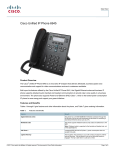
Vision HAWK Smart Camera Guide
83-016800-02 Rev D
Copyright ©2012
Microscan Systems, Inc.
Tel: 425.226.5700 / 800.251.7711
Fax: 425.226.8250
ISO 9001 Certified
Issued by TüV USA
All rights reserved. The information contained herein is proprietary and is provided solely for the purpose of
allowing customers to operate and/or service Microscan manufactured equipment and is not to be released,
reproduced, or used for any other purpose without written permission of Microscan.
Throughout this manual, trademarked names might be used. We state herein that we are using the names to the
benefit of the trademark owner, with no intention of infringement.
Disclaimer
The information and specifications described in this manual are subject to change without notice.
Latest Manual Version
For the latest version of this manual, see the Download Center on our web site at:
www.microscan.com.
Technical Support
For technical support, e-mail: [email protected].
Warranty and Terms of Sale
For Standard Warranty information, see: www.microscan.com/warranty.
Microscan Systems, Inc.
Renton Headquarters
425.226.5700 / 800.251.7711
Nashua Office
603.598.8400
Microscan Europe
011 31 172 423360
Microscan Asia Pacific
65 6846 1214
Contents
PREFACE
Welcome! v
Purpose of This Manual v
Manual Conventions v
CHAPTER 1
Introduction 1-1
Product Summary 1-2
Features and Benefits 1-2
Applications 1-3
Package Contents 1-3
Vision HAWK Smart Camera Models 1-4
Part Number Structure 1-4
CHAPTER 2
System Components 2-1
Hardware Components 2-1
Important Label Information 2-9
Mounting and Wiring the Vision HAWK Smart Camera 2-10
Input/Output Wiring 2-17
Power Requirements 2-18
Status Indicators 2-19
AutoVISION Button 2-20
Setting Up a Job in AutoVISION 2-21
CHAPTER 3
Optics and Lighting 3-1
Optics 3-2
Illumination 3-3
Vision HAWK Smart Camera Guide
iii
Contents
APPENDIX A
Connector Pinouts A-1
Vision HAWK Smart Camera Connectors A-2
APPENDIX B
Cable Specifications B-1
61-000160-01 Cable, Host, Ethernet, M12 8-pin Plug to RJ45, 1 m B-2
61-000162-01 Cable, Common, M12 12-pin Plug to M12 12-pin Socket, 1 m B-3
97-000003-01 Power Supply, M12 12-pin Socket, 1.3 m B-4
99-000020-02 Trigger, M12 4-pin Plug, NPN, Dark On, 2 m B-5
APPENDIX C
General Specifications C-1
Dimensions C-5
Field of View and Working Distance C-7
APPENDIX D
Web HMI D-1
Adding Options to the Base URL D-4
Basic Options D-4
Layout Options D-5
Settings Pages D-7
Style D-14
Additional Notes D-15
iv
Vision HAWK Smart Camera Guide
Preface
Welcome!
PREFACE
Purpose of This Manual
This manual contains detailed information about the Vision HAWK Smart
Camera.
Manual Conventions
The following typographical conventions are used throughout this manual.
•
Items emphasizing important information are bolded.
•
Menu selections, menu items and entries in screen images are
indicated as: Run (triggered), Modify..., etc.
Vision HAWK Smart Camera Guide
v
Preface
vi
Vision HAWK Smart Camera Guide
1
CHAPTER 1
Introduction
1
Introduction
FIGURE 1–1. Vision HAWK Smart Camera, C-Mount and Standard Models
Vision HAWK Smart Camera Guide
1-1
Chapter
1
Introduction
Product Summary
The Vision HAWK Smart Camera is a compact industrial smart camera
that provides powerful machine vision capabilities with a small form factor
and intuitive software interface. The Vision HAWK is designed for
industrial environments where IP65/67 enclosure and rugged M12
connectivity are required.
Fully-integrated I/O and communications make the Vision HAWK easy to
incorporate in virtually any machine vision application. Patented liquid
lens autofocus and modular optical zoom enables the Vision HAWK to
inspect objects at distances from 33 mm to 2 m and beyond.
Pressing the AutoVISION button at the back of the Vision HAWK enables
real time dynamic autofocus. When an object is centered in the field of
view and the AutoVISION button is pressed, the camera automatically
adjusts focal distance and sets internal parameters to optimize image
captures.
AutoVISION software, designed for use with the Vision HAWK, provides
an intuitive interface, step-by-step configuration, and a library of presets
that allow easy setup and deployment. For more complex vision
applications, the system can be upgraded from AutoVISION to
Visionscape.
Features and Benefits
1-2
•
Both Standard and C-Mount versions available
•
World’s first vision system with liquid lens autofocus (standard
models)
•
Integrated lighting (standard models)
•
Integrated Ethernet
•
Flexible programming options for custom applications
•
AutoVISION button for automatic targeting, calibration, and triggering
•
Simplified configuration with AutoVISION software
•
Fully scalable with Visionscape
•
Applications can be ported to Visionscape PC-based machine vision
Vision HAWK Smart Camera Guide
Applications
•
Automotive assembly verification
•
Part identification
•
Label positioning
•
Contents verification
•
Electronics assembly verification and identification
•
Semiconductor packaging and component inspection
•
Auto ID (Data Matrix and other 2D symbologies, 1D, OCR)
Introduction
Applications
Package Contents
Before you install AutoVISION software and connect your Vision HAWK
Smart Camera, please take a moment to confirm that the following items
are available:
•
Vision HAWK Smart Camera — Your package contains one of the
available models listed in Table 1–1
•
AutoVISION Software Installation USB Drive
•
Required accessories such as a power supply or power cable
Vision HAWK Smart Camera Guide
1
1-3
Chapter
1
Introduction
Vision HAWK Smart Camera Models
Table 1–1 lists and describes the Vision HAWK Smart Camera models.
TABLE 1–1. Vision HAWK Smart Camera Models
Part Number
Vision HAWK Smart Camera Model
GMV-6800-1000G
Vision HAWK, SXGA, AutoVISION, C-Mount
GMV-6800-1002G
Vision HAWK, SXGA, AutoVISION + Visionscape, C-Mount
GMV-6800-1010G
Vision HAWK, WVGA, AutoVISION, C-Mount
GMV-6800-1012G
Vision HAWK, WVGA, AutoVISION + Visionscape, C-Mount
GMV-6800-1110G
Vision HAWK, WVGA, Built-In Light, AutoVISION, 15° Lens
GMV-6800-1210G
Vision HAWK, WVGA, Built-In Light, AutoVISION, 30° Lens
GMV-6800-1310G
Vision HAWK, WVGA, Built-In Light, AutoVISION, 45° Lens
GMV-6800-1112G
Vision HAWK, WVGA, Built-In Light, AutoVISION + Visionscape, 15° Lens
GMV-6800-1212G
Vision HAWK, WVGA, Built-In Light, AutoVISION + Visionscape, 30° Lens
GMV-6800-1312G
Vision HAWK, WVGA, Built-In Light, AutoVISION + Visionscape, 45° Lens
GMV-6800-1100G
Vision HAWK, SXGA, Built-In Light, AutoVISION, 15° Lens
GMV-6800-1200G
Vision HAWK, SXGA, Built-In Light, AutoVISION, 30° Lens
GMV-6800-1300G
Vision HAWK, SXGA, Built-In Light, AutoVISION, 45° Lens
GMV-6800-1102G
Vision HAWK, SXGA, Built-In Light, AutoVISION + Visionscape, 15° Lens
GMV-6800-1202G
Vision HAWK, SXGA, Built-In Light, AutoVISION + Visionscape, 30° Lens
GMV-6800-1302G
Vision HAWK, SXGA, Built-In Light, AutoVISION + Visionscape, 45° Lens
Part Number Structure
GMV
6800
General
Machine
Vision
Vision
HAWK
Comm
Lens
Sensor
Options
RoHS
Custom
1=
Ethernet
0 = C-Mount
0 = CCD
(SXGA)
0=
AutoVISION
G = RoHS
compliant
0 to 99
1 = 15° Optics
1 = CMOS
(WVGA)
1 = Custom
2 = 30° Optics
3 = 45° Optics
1-4
2=
Visionscape
3 = Custom +
Visionscape
Vision HAWK Smart Camera Guide
2
CHAPTER 2
System Components
2
System Components
This section contains information about system components as well as
information to help you connect the Vision HAWK Smart Camera. Specific
information describes connectors, adapters, cables, pinouts, and signals.
Note: There are no user-serviceable parts inside.
Hardware Components
Table 2-1 lists Vision HAWK Smart Camera hardware components.
TABLE 2–1. Vision HAWK Smart Camera Hardware Components
Part Number
Description
Cameras
GMV-6800-1000G
Vision HAWK, SXGA, AutoVISION, C-Mount
GMV-6800-1002G
Vision HAWK, SXGA, AutoVISION + Visionscape, C-Mount
GMV-6800-1010G
Vision HAWK, WVGA, AutoVISION, C-Mount
GMV-6800-1012G
Vision HAWK, WVGA, AutoVISION + Visionscape, C-Mount
GMV-6800-1110G
Vision HAWK, WVGA, Built-In Light, AutoVISION, 15° Lens
GMV-6800-1210G
Vision HAWK, WVGA, Built-In Light, AutoVISION, 30° Lens
GMV-6800-1310G
Vision HAWK, WVGA, Built-In Light, AutoVISION, 45° Lens
GMV-6800-1112G
Vision HAWK, WVGA, Built-In Light, AutoVISION + Visionscape, 15° Lens
GMV-6800-1212G
Vision HAWK, WVGA, Built-In Light, AutoVISION + Visionscape, 30° Lens
GMV-6800-1312G
Vision HAWK, WVGA, Built-In Light, AutoVISION + Visionscape, 45° Lens
Vision HAWK Smart Camera Guide
2-1
Chapter
2
System Components
TABLE 2–1. Vision HAWK Smart Camera Hardware Components (Continued)
Part Number
Description
GMV-6800-1100G
Vision HAWK, SXGA, Built-In Light, AutoVISION, 15° Lens
GMV-6800-1200G
Vision HAWK, SXGA, Built-In Light, AutoVISION, 30° Lens
GMV-6800-1300G
Vision HAWK, SXGA, Built-In Light, AutoVISION, 45° Lens
GMV-6800-1102G
Vision HAWK, SXGA, Built-In Light, AutoVISION + Visionscape, 15° Lens
GMV-6800-1202G
Vision HAWK, SXGA, Built-In Light, AutoVISION + Visionscape, 30° Lens
GMV-6800-1302G
Vision HAWK, SXGA, Built-In Light, AutoVISION + Visionscape, 45° Lens
Demo Kit
98-000215-01
Demo Kit (Power Supply, Camera Stand, Ethernet Host Cable, Carrying Case,
Documentation)
Power Supplies
97-000003-01
Power Supply, M12 12-pin Socket, 1.3 m
97-000003-02
Power Supply, M12 12 pin Plug, 1.3m
Communication Devices and Cables
98-000103-01
QX-1 Interface Device
61-000148-01
Cordset, Common, M12 12 Pin, Socket (Ultralock) to M12 12 Pin, Plug (Ultralock), 3M
61-000148-02
Cordset, Common, M12 12 Pin, Socket (Screw-on) to M12 12 Pin Plug (Screw-on), 3M
61-000162-01
Cordset, Common, M12 12 Pin, Socket (Ultralock) to M12 12 Pin, Plug (Ultralock), 1M
61-000162-02
Cordset, Common, M12 12 Pin, Socket (Screw-on) to M12 12 Pin Plug (Screw-on), 1M
61-000153-01
Cordset, Host, Serial, M12 12 Pin Socket (Ultralock) to DB9 Socket, 1M
61-000153-02
Cordset, Host, Serial M12 12 pin Socket (Screw-on) to DB9 Socket, 1M
61-000164-01
Cordset, Host, Serial, M12 12 pin Socket (Ultralock) to DB9 Socket, 3M
61-000164-02
Cordset, Host, Serial, M12 12 pin Socket (Screw-on) to DB9 Socket, 3M
61-000152-01
Cordset, Host, Serial M12 12 pin Plug (Ultralock) to DB9 Socket, 1M
61-000152-02
Cordset, Host, Serial, M12 12 pin Plug (Screw-down) to DB9 Socket, 1M
61-000165-01
Cordset, Host, Serial M12 12 pin Plug (Ultralock) to DB9 Socket, 3M
61-000165-02
Cordset, Host, Serial M12 12 pin Plug (Screw-on) to DB9 Socket, 3M
61-000163-01
Cordset, Host, Ethernet, M12 8 pin Plug (Ultralock) to RJ45, 3M
61-000163-02
Cordset, Host, Ethernet, M12 8 pin Plug(Screw-on) to RJ45, 3M
61-000160-01
Cordset, Host, Ethernet, M12 8 pin Plug (Ultralock) to RJ45, 1M
61-000160-02
Cordset, Host, Ethernet, M12 8 pin Plug (Screw-on) to RJ45, 1M
61-000161-01
Cordset, M12 12 pin Plug (Ultralock) to MS-5100, 3M
61-000161-02
Cordset, M12 12 pin Plug (Screw-on) to MS-5100, 3M
61-000172-01
Cordset, M12 12 pin Plug (Ultralock) to M12 12 pin Socket (Ultralock) to DB25 Plug
61-000158-03
Cordset, M12 12 Pin Plug & Socket (Ultralock) to MS-Connect 210, RS-232, 2M
61-000158-04
Cordset, M12 12 Pin Plug & Socket (Ultralock) to MS-Connect 210, RS-422/485, 2M
61-000166-01
Cordset, M12 12 Pin Plug (Ultralock) to Flying Leads, 3M
61-000166-02
Cordset, M12 12 Pin Plug (Screw-on) to Flying Leads, 3M
2-2
Vision HAWK Smart Camera Guide
Hardware Components
TABLE 2–1. Vision HAWK Smart Camera Hardware Components (Continued)
Description
61-000167-01
Cordset, M12 12 Pin Socket (Ultralock) to Flying Leads, 3M
61-000167-02
Cordset, M12 12 Pin Socket (Screw-on) to Flying Leads, 3M
61-000207-01
Cordset, C-Mount-to-Smart Series Light
FIS-0210-0001G
MS-Connect 210, Connectivity Box with Display
FIS-0210-0002G
MS-Connect 210, Connectivity Box
FIS-0210-0003G
MS-Connect 210, Connectivity Box with Display and Ethernet
FIS-0210-0004G
MS-Connect 210, Connectivity Box with Ethernet
98-000013-04
Relay Module, 120VAC, 3 Amp Output, Series 70, Type SM, for MS-Connect 210
98-000013-05
Relay Module, 240VAC, 3 Amp Output, Series 70, Type SM for MS-Connect 210
98-000013-06
Relay Module, 24VDC, 3 Amp Output, Series 70, Type SM for MS-Connect 210
2
System Components
Part Number
Accessories
98-000143-01
Adapter Plate Kit
98-000148-01
L-Bracket Kit
98-000144-01
Right Angle Mirror Kit
98-000146-01
Window Replacement Kit
98-000147-01
15° Lens Kit
98-000147-02
30° Lens Kit
98-000147-03
45° Lens Kit
98-000205-01
Glass WIndow Kit with Infrared (IR) Filter
98-000206-01
Glass Window Kit
98-500006-01
Mounting Plate Kit, Flat, Custom Surfaces
20-610024-01
Trigger Connector, 4-pin Plug (screw terminal and field-wireable) (for self-wiring)
98-000037-01
Extension Kit, All Cameras, 6 inch
98-000054-01
Kit, Mounting Stand Base Plate, Small
98-000016-01
Mounting Arm/Adapter Kit, 6 inch
99-000056-01
Accessory, Bracket, DOAL 50 to Vision HAWK
99-000058-01
Accessory, Bracket, DOAL 75 to Vision HAWK
99-000060-01
Accessory, Bracket, DOAL 100 to Vision HAWK
99-000061-01
Accessory, Bracket, DOAL to C-MOUNT Vision HAWK
99-000050-01
Accessory, Bracket,R-100 to Vision HAWK
99-000052-01
Accessory, Bracket,R-60/70 to Vision HAWK
99-000049-01
Accessory, Bracket,R-100 to C-MOUNT Vision HAWK
99-000051-01
Accessory, Bracket,R-60/70 to C-MOUNT Vision HAWK
98-92800471
5MM Extension Tube for C-Mount Lenses
98-CO206
Lens Extension Tube Set 0.5, 1, 5, 10, 20, 40mm
98-92800571
Lens 8mm F/1.4-16, FT 25.5mm P 0.5mm, 2/3" C-MNT
Vision HAWK Smart Camera Guide
2-3
Chapter
2
System Components
TABLE 2–1. Vision HAWK Smart Camera Hardware Components (Continued)
Part Number
Description
98-92800572
Lens 12mm F/1.8-16, FT 25.5mm P 0.5mm, 2/3" C-MNT
98-92800573
Lens 16mm F/1.4-16, FT 25.5mm P 0.5mm, 2/3" C-MNT
98-92800574
Lens 25mm F/1.6-16, FT 25.5mm P 0.5mm, 2/3" C-MNT
98-92800575
Lens 35mm F/2.1-22, FT 25.5mm P 0.5mm, 2/3" C-MNT
98-92800576
Lens 50mm F/2.8-22, FT 25.5mm P 0.5mm, 2/3" C-MNT
98-92800577
Lens 75mm F/3.9-32, FT 25.5mm P 0.5mm, 2/3" C-MNT
98-92800311
Lens, Skylight UV Filter 25.5mm Thread
98-92800371
Polarizing Filter 25.5mm Thread
98-000218-01
Lens Protection Housing, Standard Length (up to 48mm)
98-000226-01
Lens Protection Housing, Long (up to 72mm)
Object Detectors
99-000020-01
Photo Sensor, M12 4pin Plug, NPN, Dark Off, 2m
99-000020-02
Photo Sensor, M12 4-pin Plug, NPN, Dark On, 2 m
Documentation
37-000010-01
Microscan Tools Drive (Software, User’s Manuals, Quick Start Guides, Configuration
Guides, links to other documents on Microscan website
Note: Additional hardware components are available in the Microscan Product Pricing Catalog.
2-4
Vision HAWK Smart Camera Guide
Hardware Components
Standard Vision HAWK Front
Figure 2-1 shows the front of the Vision HAWK Smart Camera.
2
System Components
FIGURE 2–1. Front
Standard Vision HAWK Base
Figure 2–2 shows the base of the Vision HAWK Smart Camera.
FIGURE 2–2. Base
Vision HAWK Smart Camera Guide
2-5
Chapter
2
System Components
Standard Vision HAWK Side
Figure 2-3 shows the side of the Vision HAWK Smart Camera.
FIGURE 2–3. Side
Standard Vision HAWK Back
Figure 2-4 shows the back of the Vision HAWK Smart Camera.
FIGURE 2–4. Back
2-6
Vision HAWK Smart Camera Guide
Hardware Components
Vision HAWK C-Mount Front
Figure 2-5 shows the front of the Vision HAWK C-Mount Smart Camera.
Vision HAWK C-Mount Base
Figure 2–6 shows the top of the Vision HAWK C-Mount Smart Camera.
FIGURE 2–6. Top
Vision HAWK Smart Camera Guide
2
System Components
FIGURE 2–5. Front
2-7
Chapter
2
System Components
Vision HAWK C-Mount Side
Figure 2-7 shows the side of the Vision HAWK C-Mount Smart Camera.
FIGURE 2–7. Side
Vision HAWK C-Mount Back
Figure 2-8 shows the back of the Vision HAWK C-Mount Smart Camera.
FIGURE 2–8. Back
2-8
Vision HAWK Smart Camera Guide
Important Label Information
Important Label Information
2
•
•
•
System Components
Each Vision HAWK Smart Camera has its own label, which contains
important information about that camera.
P/N – The Microscan part number of your Vision HAWK Smart
Camera.
S/N — The serial number of your Vision HAWK Smart Camera.
MAC — The MAC address of your Vision HAWK Smart Camera.
Vision HAWK Smart Camera Guide
2-9
Chapter
2
System Components
Mounting and Wiring the Vision HAWK Smart Camera
•
Mount the camera (1) securely as required by the application.
1
Mounting
holes
•
•
•
•
•
Connect the Ethernet cable (2) from “B” on the camera (1) to the
network.
Connect the power supply cable (3) to “3” on the QX-1 (4).
Connect the trigger (5) to “T” on the QX-1 (4).
Connect the “Common” cable (6) from “A” on the camera (1) to “2” on
the QX-1 (4).
Plug in the power supply (3).
1
1
2
6
4
3
4
5
Standard Vision HAWK
2-10
2
6
3
5
Vision HAWK C-Mount
Vision HAWK Smart Camera Guide
Mounting and Wiring the Vision HAWK Smart Camera
Optoisolated Outputs
NPN Output for Host Input
Vision HAWK Smart Camera Guide
2-11
2
System Components
The reader has optoisolated outputs that can transfer signals from the
camera to peripherals. Outputs can be configured as either NPN or PNP,
but NPN and PNP cannot be mixed in a system, because the output
common is shared by all outputs.
Chapter
2
System Components
NPN Output for External Load
2-12
Vision HAWK Smart Camera Guide
Mounting and Wiring the Vision HAWK Smart Camera
PNP Output for Host Input
System Components
2
Vision HAWK Smart Camera Guide
2-13
Chapter
2
System Components
PNP Output for External Load
2-14
Vision HAWK Smart Camera Guide
Mounting and Wiring the Vision HAWK Smart Camera
Optoisolated Inputs
NPN
Vision HAWK Smart Camera Guide
2-15
2
System Components
All discrete inputs are optoisolated. Inputs can be configured as either
NPN or PNP, but NPN and PNP cannot be mixed in a system, because
the input common is shared by all inputs.
Chapter
2
System Components
PNP
2-16
Vision HAWK Smart Camera Guide
Input/Output Wiring
Input/Output Wiring
System Components
2
Vision HAWK Smart Camera Guide
2-17
Chapter
2
System Components
Power Requirements
Refer to Table 2-3 when determining the power supply requirements for
your camera.
TABLE 2–3. Camera Power Requirements
Component
Vision HAWK Smart Camera, CCD
5-28VDC, 200mV p-p max ripple,
170mA at 24VDC (typ.)
15.5 watts (max.)
Vision HAWK Smart Camera, CMOS
5-28VDC, 200mV p-p max ripple,
135mA at 24VDC (typ.)
13 watts (max.)
Vision HAWK C-Mount Smart Camera,
CCD
5-28VDC, 200mV p-p max ripple,
130mA at 24VDC (typ.)
15.5 watts (max.)
Vision HAWK C-Mount Smart Camera,
CMOS
5-28VDC, 200mV p-p max ripple,
105mA at 24VDC (typ.)
13 watts (max.)
2-18
Vision HAWK Smart Camera Guide
Status Indicators
Status Indicators
TRIG = Trigger Status
PASS/FAIL = Inspection Status
MODE = Camera Status
Outputs 1, 2, 3
Power Status
LINK/ACT = Link Activity Status
TRIG
PASS/FAIL
MODE
LINK/ACT
PWR
OUTPUTS
On Steady
Continuous Trigger
Off
Waiting for Trigger Event
On Flashing
Trigger Event
On
Active State
Off
Inactive State
On Steady
Unit Ready
Off
Unit Not Ready
On Steady
Link Established
Off
No Link/Activity
On Flashing
Link Established and Activity on Link
On
Power On
Off
No Power Applied to Unit
On
Signal Sent to External Output
Off
No Signal Sent to External Output
Additional User Feedback
•
Green Flash – A green flash from the front of the unit indicates a Good Read.
•
Red X Targeting Pattern – The red X targeting pattern from the front of
the unit allows the user to center an object in the camera’s field of view.
•
Beeper – The beeper is an audible verification that either a Pass or a
Fail has occurred.
Vision HAWK Smart Camera Guide
2
System Components
The top of the Vision HAWK Smart Camera has multiple LEDs that indicate
different trigger, inspection, camera, communication, and power states.
2-19
Chapter
2
System Components
AutoVISION Button
The AutoVISION Button has two positions, selectable by the length of
time the button is held down, and indicated by one or two beeps in
succession. It can also be used to send a trigger signal when Send
Trigger is checked in AutoVISION software’s Connect view. When the
trigger functionality is enabled, pushing the AutoVISION Button triggers
the camera to capture an image.
1st Position: Red Targeting Pattern
The first AutoVISION Button position turns the targeting system on.
This overrides any other targeting modes that have been configured.
2nd Position: Auto Calibration
The second AutoVISION Button position starts the Auto Calibration
process, which selects the appropriate photometry and focus settings
for the camera. The selected values are then saved for power-on.
2-20
Vision HAWK Smart Camera Guide
Setting Up a Job in AutoVISION
Setting Up a Job in AutoVISION
1.
Configure Vision HAWK hardware.
1
3
7
2
6
8
See Appendix A, Connector Pinouts, for
Vision HAWK pin assignments.
Item Description
Part Number
1
Vision HAWK Smart Camera
GMV-6800-XXXXG
2
QX-1 Interface Device
98-000103-02
3
Cordset, Common, M12 12-pin Plug to M12 12-pin
Socket, 1 m
61-000162-01
4
Cordset, Host, Serial, M12 12-pin Plug to DB9, 1 m
61-000152-01
5
Cordset, Host, Serial, M12 12-pin Socket to DB9, 1 m
61-000153-01
6
Power Supply, M12 12-pin Socket, 1.3 m
97-000003-01
7
Cordset, Host, Ethernet, M12 8-pin Plug to RJ45, 1 m
61-000160-01
8
Trigger, M12 4-pin Plug, NPN, Dark On, 2 m
99-000020-02
Note: Additional cables available in the Microscan Product Pricing Catalog.
Vision HAWK Smart Camera Guide
2-21
2
System Components
AutoVISION is a critical component of the Vision HAWK’s functionality.
Designed for use with the Vision HAWK, AutoVISION provides an intuitive
interface, step-by-step configuration, and a library of presets that allow
easy setup and deployment. For more complex vision applications, the
system can be upgraded from AutoVISION to Visionscape.
Chapter
2
System Components
–
–
–
–
–
–
2.
Mount the camera as required by the application.
Connect the Ethernet cable from "B" on the camera to the
network.
Connect the power supply to "3" on the QX-1.
Connect the photo sensor to "T" on the QX-1.
Connect the "Common" cable to "2" on the QX-1 and "A" on the
camera.
Plug in the power supply.
Select your Vision HAWK in the AutoVISION Connect view, create a
job, and adjust camera settings.
AutoVISION's Connect view allows you to select your device and
configure its settings, and to create a new job. The Select Device
dropdown menu provides a list of available devices. Hover the mouse
over a device to see its details.
2-22
Vision HAWK Smart Camera Guide
Setting Up a Job in AutoVISION
Note: The default IP address of the camera is: 192.168.0.10. Be sure
your PC is on the same subnet (192.168.0.100, for example).
Modify camera settings in the
Details area at the left of the
Connect view.
Create, Load, or Upload a job
using the buttons in the center
of the Connect view.
Important: When modifying camera settings, you will need to enter a
username and password for the camera. The default username and
password are:
–
Username: Microscan
–
Password: vision
Vision HAWK Smart Camera Guide
2-23
2
System Components
Click the lock icon to take control of the camera. When you have
control of the camera, the Modify button will appear beneath the
camera settings. Click the Modify button to adjust camera settings.
Chapter
2
System Components
Once you have selected your camera, adjusted its settings, and
created a new job, you will move to the Image view. This view allows
you to Auto Calibrate the camera, and to manually adjust the
camera's Exposure, Gain, and Focus, and also to set the Lighting
Mode (On, Off, or Strobe).
3.
Edit the Job in AutoVISION.
After you have created a new job, loaded a job from your PC, or
uploaded a job from the camera, you will proceed to the Edit view to
refine your machine vision job. The Camera parameters below the
captured image allow you to set Gain, Exposure, Focus, Trigger, and
Lighting. Inspection Outputs options allow you to connect your job to
the outside world. This is also the view where you can add multiple
tools to the job. The tool icons are located above the main view area.
2-24
Vision HAWK Smart Camera Guide
Setting Up a Job in AutoVISION
4.
Run the Job in AutoVISION.
2
System Components
Going to the Run view will automatically download your job to the
camera and start it running.
5.
Save the Job.
Click the Save to Camera icon on the File menu bar to save the job
to the Vision HAWK.
Vision HAWK Smart Camera Guide
2-25
Chapter
2-26
2
System Components
Vision HAWK Smart Camera Guide
3
CHAPTER 3
Optics and Lighting
This section describes the optical and illumination characteristics of the
Vision HAWK Smart Camera.
Optics and Lighting
3
Vision HAWK Smart Camera Guide
3-1
Chapter
3
Optics and Lighting
Optics
The Vision HAWK Smart Camera is available with a built-in CMOS sensor
or CCD sensor.
Optics Specifications
Part Number
Sensor
GMV-68001100G
GMV-68001200G
GMV-68001300G
CCD, Global Shutter
Sensor Color
Resolution
Part Number
Sensor
Part Number
Sensor
1” (33 mm) to ∞ (liquid lens autofocus)
GMV-68001102G
GMV-68001202G
GMV-68001302G
Focal Range
Shutter
3-2
Exposure: 25us to 100ms (1/40,000 to 1/10)
Default = 400us (1/2,500)
GMV-68001112G
CCD, Global Shutter
GMV-68001212G
GMV-68001312G
CMOS, Global Shutter
Monochrome
SXGA (1280 x 960) CCD
WVGA (752 x 480) CMOS
1” (33 mm) to ∞ (liquid lens autofocus)
Exposure: 6us to 100ms (1/150,000 to 1/10)
Default = 666us (1/1,500)
GMV-6800-1000G
GMV-6800-1002G
Exposure: 25us to 100ms (1/40,000 to 1/10)
Default = 400us (1/2,500)
GMV-6800-1010G
CCD, Global Shutter
Sensor Color
Resolution
WVGA (752 x 480) CMOS
Exposure: 6us to 100ms (1/150,000 to 1/10)
Default = 666us (1/1,500)
Focal Range
Shutter
GMV-68001310G
Monochrome
Sensor Color
Resolution
GMV-68001210G
CMOS, Global Shutter
SXGA (1280 x 960) CCD
Focal Range
Shutter
GMV-68001110G
GMV-6800-1012G
CMOS, Global Shutter
Monochrome
SXGA (1280 x 960) CCD
WVGA (752 x 480) CMOS
Depends on lens
Exposure: 6us to 100ms (1/150,000 to 1/10)
Default = 666us (1/1,500)
Exposure: 25us to 100ms (1/40,000 to 1/10)
Default = 400us (1/2,500)
Vision HAWK Smart Camera Guide
Illumination
Illumination
The standard version of the Vision HAWK Smart Camera has built-in
lighting (red LEDs for SXGA models and white LEDs for QXGA models).
The LEDs can be configured to operate in multiple modes – Continuous,
Strobe, and Off.
Lighting Specifications
Part Number
GMV-68001100G
GMV-68001200G
GMV-68001300G
GMV-68001110G
GMV-68001210G
GMV-68001310G
GMV-68001102G
GMV-68001202G
GMV-68001302G
GMV-68001112G
GMV-68001212G
GMV-68001312G
Red @ 617nm
LED Color
3
Optics and Lighting
Important: The Vision HAWK C-Mount (GMV-6800-1000G, GMV-68001002G, GMV-6800-1010G, GMV-6800-1012G) does not have built-in
lighting. The Machine Vision Lighting Principles on the following page
provide some suggestions for how to determine the appropriate external
lighting for your application.
Vision HAWK Smart Camera Guide
3-3
Chapter
3
Optics and Lighting
Machine Vision Lighting Principles
Proper lighting is critical to the success of a machine vision
application. Depending on the requirements of your application, you
may also need to add external lighting from Microscan’s NERLITE
family of machine vision lighting products.
Consider the following when setting up your application:
–
Is the surface of the object flat, slightly bumpy, or very bumpy?
–
Is the surface matte or shiny?
–
Is the object curved or flat?
–
What is the color of the object or area being inspected?
–
Is the object moving or stationary?
Machine vision lighting should maximize contrast of the areas or features
being inspected while minimizing the contrast of everything else.
Before correct lighting
3-4
After correct lighting with
a NERLITE CDI Illuminator
Vision HAWK Smart Camera Guide
Illumination
External Illumination Control
The Vision HAWK C-Mount Smart Camera supports external lighting with
Microscan’s NERLITE Smart Series lights. The diagram below
demonstrates how the camera and light can be configured with two QX-1
interface devices. The light is controlled using the Lighting control in the
Camera configuration settings of AutoVISION software.
The camera’s trigger is synchronized with the light to create a strobe
effect for reliable image acquisition.
Optics and Lighting
3
Vision HAWK Smart Camera Guide
3-5
Chapter
3-6
3
Optics and Lighting
Vision HAWK Smart Camera Guide
A
Connector Pinouts
APPENDIX A
This section contains information about Vision HAWK Smart Camera
connectors:
•
M12 12-Pin Plug on page A-2
•
M12 8-Pin Socket on page A-3
Connector Pinouts
A
Vision HAWK Smart Camera Guide
A-1
Appendix
A
Connector Pinouts
Vision HAWK Smart Camera Connectors
Connector A – M12 12-Pin Plug – Power, I/O, and Serial
Figure A–1 shows the M12 12-pin plug at connector A.
FIGURE A–1. Connector A – M12 12-Pin Plug
Table A–1 describes the M12 12-pin plug signals.
TABLE A–1. Connector A – M12 12-Pin Plug
A-2
Pin
Function
1
Trigger
2
Power
3
Default
4
Input 1
5
Output 1
6
Output 3
7
Ground
8
Input Common
9
Host RxD
10
Host TxD
11
Output 2
12
Output Common
Vision HAWK Smart Camera Guide
Vision HAWK Smart Camera Connectors
Connector B – M12 8-Pin Socket – Ethernet
Figure A-2 shows the M12 8-pin socket at connector B.
FIGURE A–2. Connector B – M12 8-Pin Socket
Table A-2 describes the M12 8-pin socket signals.
TABLE A–2. Connector B – M12 8-Pin Socket
Function
1
Terminated
2
Terminated
3
Terminated
4
TX (–)
5
RX (+)
6
TX (+)
7
Terminated
8
RX (–)
Vision HAWK Smart Camera Guide
A
Connector Pinouts
Pin
A-3
Appendix
A-4
A
Connector Pinouts
Vision HAWK Smart Camera Guide
B
APPENDIX B
Cable Specifications
B
Cable Specifications
This section contains information about Vision HAWK Smart Camera
cables.
Note: Cable specifications are published for information only. Microscan
does not guarantee the performance or quality of cables provided by
other suppliers.
TABLE B–1. Cable Part Numbers and Descriptions
Part Number
Descriptions
61-000160-01
Cable, Host, Ethernet, M12 8-pin Plug to RJ45, 1 m
61-000162-01
Cable, Common, M12 12-pin Plug to M12 12-pin
Socket, 1 m
97-000003-01
Power Supply, M12 12-pin Socket, 1.3 m
99-000020-02
Trigger, M12 4-pin Plug, NPN, Dark On, 2 m
Vision HAWK Smart Camera Guide
B-1
Appendix
B
Cable Specifications
61-000160-01 Cable, Host, Ethernet, M12 8-pin Plug to RJ45, 1 m
The 61-000160-01 Cable, Host, Ethernet, M12 8-pin Plug to RJ45, 1 m is
a 1 meter cable with an 8-pin M12 Ultra-Lock connector on one end and a
standard RJ45 connector on the other end.
Figure B-1 shows the 61-000160-01 Cable, Host, Ethernet, M12 8-pin Plug
to RJ45, 1 m.
FIGURE B–1. Cable, Host, Ethernet, M12 8-pin Plug to RJ45, 1 m
M12 8-Pin Plug
RJ45
Important: Be sure that the retaining clip on the RJ45 connector has
locked into place in the Ethernet receptacle on the PC and is not being
impeded by the rubber housing.
Note: A screw-down version of this cable is also available (61-000160-02).
B-2
Vision HAWK Smart Camera Guide
61-000162-01 Cable, Common, M12 12-pin Plug to M12 12-pin
Socket, 1 m
The 61-000162-01 Cable, Common, M12 12-pin Plug to M12 12-pin
Socket, 1 m is a 1 meter cable with a 12-pin M12 plug on one end and a
12-pin M12 socket on the other end.
Figure B-2 shows the 61-000162-01 Cable, Common, M12 12-pin Plug to
M12 12-pin Socket, 1 m.
FIGURE B–2. Cable, Common, M12 12-pin Plug to M12 12-pin Socket, 1 m
Note: A screw-down version of this cable is also available (61-000162-02).
Vision HAWK Smart Camera Guide
B-3
B
Cable Specifications
61-000162-01 Cable, Common, M12 12-pin Plug to M12 12-pin Socket, 1 m
Appendix
B
Cable Specifications
97-000003-01 Power Supply, M12 12-pin Socket, 1.3 m
The 97-000003-01 Power Supply, M12 12-pin Socket, 1.3 m is a 90-254
VAC, +24VDC power supply.
Figure B-3 shows the 97-000003-01 Power Supply, M12 12-pin Socket,
1.3 m.
FIGURE B–3. Power Supply, M12 12-pin Socket, 1.3 m
M12 12-Pin Socket
B-4
Vision HAWK Smart Camera Guide
99-000020-02 Trigger, M12 4-pin Plug, NPN, Dark On, 2 m
The 99-000020-02 Trigger, M12 4-pin Plug, NPN, Dark On, 2 m is a photo
sensor with a 4-pin M12 connector.
Figure B-4 shows the 99-000020-02 Trigger, M12 4-pin Plug, NPN, Dark
On, 2 m.
FIGURE B–4. Trigger, M12 4-pin Plug, NPN, Dark On, 2 m
99-000020-02 Schematic
Vision HAWK Smart Camera Guide
B-5
B
Cable Specifications
99-000020-02 Trigger, M12 4-pin Plug, NPN, Dark On, 2 m
Appendix
B-6
B
Cable Specifications
Vision HAWK Smart Camera Guide
C
APPENDIX C
General
Specifications
C
General Specifications
This section contains specifications and dimensions for the Vision HAWK
Smart Camera and Vision HAWK C-Mount Smart Camera.
TABLE C–1. General Specifications
Part Number
Sensor
GMV-68001100G
GMV-68001200G
GMV-68001300G
GMV-68001110G
SXGA (1280 x 960) CCD
Sensor Color
GMV-68001310G
WVGA (752 x 480) CMOS
Monochrome
Height
1.59” (40.5 mm)
Width
2.27” (57.6 mm)
Depth
3.79” (96.3 mm)
Weight
10 oz. (280 g)
Power
GMV-68001210G
5-28VDC, 200mV p-p max ripple, 170mA at
24VDC (typ.), 15.5 watts (max.)
5-28VDC, 200mV p-p max ripple, 135mA at
24VDC (typ.), 13 watts (max.)
Connector
M12 12-pin Ultra-Lock (Connector A) and M12 8-pin Ultra-Lock (Connector B)
Lens Type
Built-In Liquid Lens
Communications
RS-232 or Ethernet
Illumination
High Output LEDs: .564mW, 470, 525, 617nm
Laser Output
5.0mW max.; Type: Laser diode; Output Wavelength: 655nm nominal; Operating Life:
50,000 hours @ 25° C; Safety Class: Class 1 Visible Laser
Indicators
I/O
LEDs: Trigger, Pass, Fail, Mode, Power, Network Activity, I/O; Green Flash: Pass; Red X:
Target
Learn/Trigger: Bi-directional, optoisolated, 4.5–28V rated, (13mA at 24VDC); Outputs (1, 2,
3): Bi-directional, optoisolated, 1–28V rated, (ICE <100mA at 24VDC, current limited by user)
Vision HAWK Smart Camera Guide
C-1
Appendix
C
General Specifications
TABLE C–1. General Specifications (Continued)
Image
Acquisition
Progressive scan, square pixel
Focal Range
1” (33 mm) to ∞ (liquid lens autofocus)
Shutter
Operating
Temperature
Storage
Temperature
Humidity
Compliance
C-2
Exposure: 6us to 100ms (1/150,000 to 1/10)
Default = 666us (1/1,500)
Exposure: 25us to 100ms (1/40,000 to 1/10)
Default = 400us (1/2,500)
0° to 45° C (32° to 118° F)
0° to 50° C (32° to 122° F)
–29° to 70° C (–20° to 158° F)
Up to 90% (non-condensing)
CDRH, FCC, UL/cUL, CE (General Immunity for Light Industry: EN 55024:1998 ITE
Immunity Standard; Radiated and Conducted Emissions of ITE Equipment: EN 55022:98
ITE Disturbances), CB, BSMI
Vision HAWK Smart Camera Guide
TABLE C–1. Specifications (Continued)
Sensor
GMV-68001102G
GMV-68001202G
GMV-68001302G
GMV-68001112G
SXGA (1280 x 960) CCD
Sensor Color
GMV-68001312G
1.59” (40.5 mm)
Width
2.27” (57.6 mm)
Depth
3.79” (96.3 mm)
Weight
10 oz. (280 g)
5-28VDC, 200mV p-p max ripple, 170mA at
24VDC (typ.), 15.5 watts (max.)
5-28VDC, 200mV p-p max ripple, 135mA at
24VDC (typ.), 13 watts (max.)
Connector
M12 12-pin Ultra-Lock (Connector A) and M12 8-pin Ultra-Lock (Connector B)
Lens Type
Fixed Lens
Communications
RS-232 or Ethernet
Illumination
High Output LEDs: .564mW, 470, 525, 617nm
Laser Output
5.0mW max.; Type: Laser diode; Output Wavelength: 655nm nominal; Operating Life:
50,000 hours @ 25° C; Safety Class: Class 1 Visible Laser
Indicators
I/O
LEDs: Trigger, Pass, Fail, Mode, Power, Network Activity, I/O; Green Flash: Pass; Red X:
Target
Learn/Trigger: Bi-directional, optoisolated, 4.5–28V rated, (13mA at 24VDC); Outputs (1, 2,
3): Bi-directional, optoisolated, 1–28V rated, (ICE <100mA at 24VDC, current limited by user)
Image
Acquisition
Progressive scan, square pixel
Focal Range
Shutter
Operating
Temperature
1” (33 mm) to ∞ (liquid lens autofocus)
Exposure: 6us to 100ms (1/150,000 to 1/10)
Default = 666us (1/1,500)
Exposure: 25us to 100ms (1/40,000 to 1/10)
Default = 400us (1/2,500)
0° to 45° C (32° to 118° F)
0° to 50° C (32° to 122° F)
Storage
Temperature
–29° to 70° C (–20° to 158° F)
Humidity
Compliance
Up to 90% (non-condensing)
CDRH, FCC, UL/cUL, CE (General Immunity for Light Industry: EN 55024:1998 ITE
Immunity Standard; Radiated and Conducted Emissions of ITE Equipment: EN 55022:98
ITE Disturbances), CB, BSMI
Vision HAWK Smart Camera Guide
C
WVGA (752 x 480) CMOS
Monochrome
Height
Power
GMV-68001212G
C-3
General
Specifications
Part Number
Appendix
C
General Specifications
TABLE C–1. Specifications (Continued)
Part Number
Sensor
GMV-6800-1000G
GMV-6800-1002G
GMV-6800-1010G
SXGA (1280 x 960) CCD
Sensor Color
WVGA (752 x 480) CMOS
Monochrome
Height
4.03” (102.3 mm)
Width
2.27” (57.6 mm)
Depth
1.59” (40.5 mm)
Weight
11 oz. (320 g)
Power
GMV-6800-1012G
5-28VDC, 200mV p-p max ripple, 130mA at
24VDC (typ.), 15.5 watts (max.)
5-28VDC, 200mV p-p max ripple, 105mA at
24VDC (typ.), 13 watts (max.)
Connector
M12 12-pin Ultra-Lock (Connector A) and M12 8-pin Ultra-Lock (Connector B)
Lens Type
C-Mount Lens
Communications
Illumination
RS-232 or Ethernet
External Illumination Required
Laser Output
Indicators
I/O
Image
Acquisition
N/A
LEDs: Trigger, Pass, Fail, Mode, Power, Network Activity, I/O
Learn/Trigger: Bi-directional, optoisolated, 4.5–28V rated, (13mA at 24VDC); Outputs (1, 2,
3): Bi-directional, optoisolated, 1–28V rated, (ICE <100mA at 24VDC, current limited by user)
Progressive scan, square pixel
Focal Range
Shutter
Operating
Temperature
Storage
Temperature
Humidity
Compliance
C-4
Depends on lens
Exposure: 6us to 100ms (1/150,000 to 1/10)
Default = 666us (1/1,500)
Exposure: 25us to 100ms (1/40,000 to 1/10)
Default = 400us (1/2,500)
0° to 45° C (32° to 118° F)
0° to 50° C (32° to 122° F)
–29° to 70° C (–20° to 158° F)
Up to 90% (non-condensing)
CDRH, FCC, UL/cUL, CE (General Immunity for Light Industry: EN 55024:1998 ITE
Immunity Standard; Radiated and Conducted Emissions of ITE Equipment: EN 55022:98
ITE Disturbances), CB, BSMI
Vision HAWK Smart Camera Guide
Dimensions
Dimensions
C
General
Specifications
FIGURE C–1. Vision HAWK Smart Camera Dimensions
Vision HAWK Smart Camera Guide
C-5
Appendix
C
General Specifications
FIGURE C–2. Vision HAWK C-Mount Smart Camera Dimensions
C-6
Vision HAWK Smart Camera Guide
Field of View and Working Distance
Field of View and Working Distance
General
Specifications
C
Vision HAWK Smart Camera Guide
C-7
Appendix
C-8
C
General Specifications
Vision HAWK Smart Camera Guide
D
Web HMI
D
Web HMI
APPENDIX D
This appendix contains information about Vision HAWK support for
Visualization HMIs.The Vision HAWK features a built in runtime
monitoring web page that can be viewed from any supported browser on
the same network. Supported browsers include:
•
Internet Explorer 5.0 or later
•
Firefox 3.0 or later
Vision HAWK Smart Camera Guide
D-1
Appendix
D
Web HMI
A built-in runtime HTML monitoring page suitable for HMI Panels that
support Internet Explorer 5.0 or later browser such as the SIMATIC M277
Panel is available on the Vision HAWK. Note that the runtime page can
also be displayed with the Firefox or Safari web browsers.
The Runtime Page shows an image from the Vision HAWK, along with
inspection counters and buttons to control certain aspects of the display.
A title bar displays the camera name, ip address and resolution. Options
are available to change if and where the counters, buttons, and titlebar
are displayed. Additionally, up to 10 results values from the job can be
displayed along with each image. These values can either be overlayed
over the image, or shown as a tabular report underneath the image.
All settings and options are set by the user via a series of option pages
which can appear over the main display. All parameters are saved as
cookies in the web browser environment, so that the next time the
Runtime Page is loaded for that device, the layout and settings are
retained.
The Runtime Image Page is accessed via a URL which contains the IP
address of the camera, and optional parameters. The default page is
accessed by simply specifying the IP address of the camera in a web
browser, for example:
http:// 161.218.121.58 (example only, actual IP address of the Vision
HAWK should be used)
If no previous settings have been set by the user, the display will be
similar to the following:
D-2
Vision HAWK Smart Camera Guide
The default behavior is:
D
Images and counters are for the first inspection in the job
•
All images (pass & fail) are shown
•
The display is automatically refreshed at regular intervals (auto=on)
•
Graphics are overlaid on the image (note: not all graphics are
available)
•
A border is drawn around the image signifying the status of the
inspection: green=pass, red=fail
Web HMI
•
The web page includes the following elements:
•
Title Bar specifying the name of the camera, IP address, and job
(avp) filename. Note that the file extension (.avp) is removed from the
displayed filename.
•
Failures Push Button – when this button is selected, only images
related to failed inspections are displayed
•
Auto Push Button – when this button is selected, the image and
counters are updated automatically. If the button is not selected, both
the image and counters are frozen.
•
Refresh Push Button – pushing this button manually updates the
image and counters
•
Status – the run status of the inspection – RUNNING or STOPPED
Vision HAWK Smart Camera Guide
D-3
Appendix
D
•
Web HMI
Counters – the Total, Pass, Fail and Alarm counters are shown for
the selected inspection
Adding Options to the Base URL
An option can be specified by adding it to the end of the URL as follows:
http://ip_address/?option=value
Note the question mark “?” separating the URL from the optional
parameter(s).
Additional options are specified by separating them with the ampersand
“&” character.
http://ip_address/?option1=value1&option2=value2&option3=value3
Basic Options
NOTE: Some basic options can be changed by specifying optional values
at the end of the URL. A much richer superset of these options can be
configured by using the Settings Pages described below. It is possible to
completely control the behavior of the Runtime Page without the use of
optional parameters in the URL.
The graphics overlay can be turned on or off by using the “graphics” URL
option. This is a setting that can have the value “on” or “off”. As an
example, to turn the display of graphics off, the web page can be
launched with the following URL:
http:// 161.218.121.58/?graphics=off
D-4
Vision HAWK Smart Camera Guide
Web HMI
D
Note: ROI graphics are not produced by applications created by
AutoVISION. They are displayed for applications created in Visionscape
FrontRunner.
Layout Options
The overall layout of the Runtime Page can be configured. To change the
layout, use the Settings screens as described in the next section. The
following shows a default configuration:
Vision HAWK Smart Camera Guide
D-5
Appendix
D
Web HMI
Buttons, status, and counters appear to the right of the image area. The
buttons are size for use via a touch screen.
The following illustrates that the layout has been changed to position the
counters at the top, shown without titles to save room. Additionally, an
Options button now appears in the right side area.
Another example with buttons and counters at the top:
D-6
Vision HAWK Smart Camera Guide
It is also possible to hide all elements except the image.
All of the options and settings can be configured by using the settings
pages. By default, there is no “Settings” button, so to show the settings
pages, the URL should be specified with the “setopt=1” parameter as
follows:
http://ip_address/?setopt=1
This will display the Runtime Page overlayed with the Options Setup page
as follows:
The tabs at the top of the screen can be used to navigate between the
several setup pages. To close the setup screens and return to the main
display, use the close button (“X”) at the upper right corner.
Vision HAWK Smart Camera Guide
D-7
Web HMI
D
Settings Pages
Appendix
D
Web HMI
The Layout page controls many layout features, which are organized into
groups. Selecting the Modes group results in the following options being
displayed:
Refer to the table below for a description of the various settings. The
other groups of settings appear as follows:
Image Display:
D-8
Vision HAWK Smart Camera Guide
Buttons:
Web HMI
D
Counters and Status:
Extra Settings:
Vision HAWK Smart Camera Guide
D-9
Appendix
D
Web HMI
As each option is checked or unchecked, the effect can be seen
immediately by observing the layout of the Runtime Page shown behind
the Options Setup Page.
D-10
Vision HAWK Smart Camera Guide
Web HMI
D
Pressing the Save button will save these settings so that they become the
default behavior the next time the page is launched.
Pressing the Defaults button will reset the stored settings to the original
defaults the next time the page is launched.
The Close button (“X” in upper right corner) will return to the main
Runtime Page.
Vision HAWK Smart Camera Guide
D-11
Appendix
D
Web HMI
The Report Tab brings up the following Report Setup screen:
Data Values from datums in the selected inspection can be formatted and
overlaid on the displayed image or shown in a table below the image. This
is specified by assigning one of 10 data report slots. If overlayed on the
image, each of these slots will represent a row in the display area, which
is evenly split into 10 equal sized rows. The spacing will depend on the
overall size of the display area, which in turn is dependant on the
dimensions of the browser window. If the report is shown in list form, each
slot corresponds to one of 10 rows.
Selecting a slot to configure results in the following display:
D-12
Vision HAWK Smart Camera Guide
This would display the value overlaid over the image near the top of the
image display area. If D5 had been used instead, it would appear closer
to the center.
By default, the displayed format will be appropriate for the datum type
requested. However the format can be changed by specifying a printf
style format string.
The format codes must be consistent with the expected data types. If the
result is an integer, then a %d format is expected, floating point numbers
require %f type formats. The list of format codes is not documented here,
refer to printf documentation.
For array values, each element of the array will be passed in turn to the
format string. For example, if a PointDm is being used, there are four
expected array values corresponding to X, Y, angle, scale. (The order is
the same as for variant access via VB). An example of using a format for
PointDm:
(%.2f,%.2f) angle=%.1f scale=%.1f
This will display a result similar to:
(23.23,45.10) angle=3.2 scale=1.0
The later array values can be considered optional and can be omitted if
desired. For example, to display just the x and y values of a PointDm, use
the format string:
center = (%6.2f, %6.2f)
This will display a result similar to:
center = (134.22, 452.12)
If no format string is specified, an appropriate default format is used. For
example, for a LineDm, by default the datum value will be displayed as:
A = value, B = value, C = value
Vision HAWK Smart Camera Guide
D-13
D
Web HMI
At a minimum the path to a datum must be specified. The inspection is
implied, so it is not in the path. In the example above, the path
Snapshot1.Blob1.BlbFlt1.CentPt is specified in the first slot.
Appendix
D
Web HMI
Style
The default display of a report value is left justified, and uses a default
font and color. If desired, all visual aspects of the displayed report value
can be modified. If the Style field is used, it has the format:
style:value,style:value,…
For example, set the text size to 9pt, and align to the right, the following
can be specified:
size:9pt,align:right
Possible style values:
It is permitted to use CSS identifiers to alter other display aspects. For
example, the following will show a red background color for the text:
backgroundColor:red
To set some of the more common styles, the combo boxes for Style, Size,
Color, and Opacity can be used. The styles field will automatically be
updated.
D-14
Vision HAWK Smart Camera Guide
Selecting the URL tab brings up the following display:
Web HMI
D
The displayed URL can be copied and then used in a browser window to
completely replicate the current setup.
Additional Notes:
•
Line breaks can be inserted into format strings by using embedded
HTML codes. To introduce a line break, use “<br />”
•
Commands and options are case sensitive. This is a limitation of
javascript and CSS.
•
A new Frontrunner feature allows copying a path of a datum to the
clipboard. Right-click the Datum name in the DatumGrid display, and
select the “Copy path to clipboard” option.
Vision HAWK Smart Camera Guide
D-15
Appendix
D-16
D
Web HMI
Vision HAWK Smart Camera Guide