1
2 Operation elements and connectors
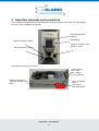
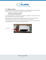
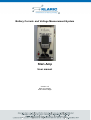
In this chapter will be described the operating elements and connectors of the base unit. After opening
the cover you find following components :
PDA with Klari-Ampsoftware
PDA-holding
LED of the battery monitor
Switch for operation mode:
„Meas“ or „Load“
Key of the battery monitor
At the side are following connectors :
Loading socket:
Red = Plus,
Blue = Minus
(14.4 V / 800mA)
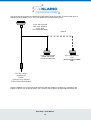
Additional sockets for
external connection of the
PDA
15pin. Sub-D-HDsocket
connection to
Klari-Mod-Module
Klari-Amp – User Manual
5